Untitled - COMEVAL
Untitled - COMEVAL
Untitled - COMEVAL

Create successful ePaper yourself
Turn your PDF publications into a flip-book with our unique Google optimized e-Paper software.
Unival® BUTTERFLY VALVES<br />
Index<br />
Data Sheets Manual<br />
Engineering Data 4-9<br />
General Design Considerations 10-11<br />
Flow Data 12-13<br />
Seats - Application Guide 14<br />
Valve Coding 15<br />
Attributes of Design - Wafer Series 700 16<br />
Parts and materials - Wafer Series 700 17<br />
Dimensions - Wafer Series 700 DN32-600 18<br />
Dimensions - Wafer Series 700 DN700-1200 19<br />
Attributes of Design - Wafer Series 701 20<br />
Parts and materials - Wafer Series 701 21<br />
Dimensions - Wafer Series 701 DN40-300 22<br />
Dimensions - Wafer Series 701 DN350-600 23<br />
Attributes of Design - Lug Series 750 24<br />
Parts and materials - Lug Series 750 25<br />
Dimensions - Lug Series 750 26<br />
Assembling Set 27<br />
Attributes of Design - U Type Series 7U 28<br />
Parts and Materials - U Type Series 7U 29<br />
Dimensions - U Type Series 7U 30<br />
Attributes of Design - Double Flange Series 790 31<br />
Parts and Materials - Double Flange Series 790 32<br />
Dimensions - Double Flange Series 790 33<br />
Grooved Ends Butterfl y Valves 34<br />
Attributes of Design - Grooved Ends Series 760 35<br />
Parts and Materials - Grooved Ends Series 760 36<br />
Dimensions - Grooved Ends Series 760 37<br />
Attributes of Design - Double Eccentric Series 791 38<br />
Parts and Materials - Double Eccentric Series 791 39<br />
Dimensions - Double Eccentric Series 791 40<br />
Triple Eccentric Butterfl y Valves (Under construction)<br />
Actuation and Accessories 41-44<br />
Torque Values for Actuators Sizing 45<br />
Pneumatic Actuators 46-54<br />
Parts and Materials - With Pneumatic Actuator - Wafer Series 700 55<br />
Dimensions - With Pneumatic Actuator - Wafer Series 700 56<br />
Parts and Materials - With Pneumatic Actuator - Lug Series 750 57<br />
Parts and Materials - With Pneumatic Actuator - Lug Series 750 58<br />
Dimensions - With Pneumatic Actuator - Lug Series 750 59<br />
Electric Actuators 60-68<br />
Parts and Materials - With Electric Actuator - Wafer Series 700 69<br />
Dimensions - With Electric Actuator - Wafer Series 700 DN32-600 70<br />
Parts and Materials - With Electric Actuator - Lug Series 750 71<br />
Dimensions - With Electric Actuator - Lug Series 750 72<br />
Installation, Start-Up and Maintenance 73-76<br />
Material Selection Guidance 77-83<br />
Data subject to change without prior notice<br />
3
Unival® BUTTERFLY VALVES<br />
Engineering Data<br />
Data Sheets Manual<br />
Equivalent DIN / ANSI Material Designation for Cast Valve Material<br />
DIN Nº Material AISI / ASTM<br />
GG20 - EN JL 1030 - EN GJL 200 0.5020 A48 30B<br />
GG25 - EN JL 1040 - EN GJL 250 0.5020 A48 40B<br />
GGG40 - EN JS 1030 - EN GJS 400-15 0.7040 60-40-18<br />
GGG40.3 - EN JS 1020 - EN GJS 400-18 0.7043 -<br />
GGG50 - EN JS 1050 - EN GJS 500-7 0.7050 65-45-12<br />
Specifications of Carbon Steel, Stainless and Exotic Materials acc. ASTM Standards<br />
Material<br />
Specification<br />
FORGED CARBON STEEL ASTM 105<br />
CAST CARBON STEEL<br />
ASTM A216WCB<br />
LOW TEMPERATURE CARBON STEEL(ALLOY) ASTM A352 LCB ASTM A352 LCC<br />
CARBON STEEL(ALLOY) CrMo<br />
ASTM A217 WC6<br />
LOW ALLOY CARBON STEEL<br />
ASTM A487 Gr4N ASTM A487 Gr4C<br />
STAINLESS STEEL. 410<br />
ASTM A217 CA15<br />
STAINLESS STEEL. 9%Cr<br />
ASTM A217 CA12<br />
STAINLESS STEEL. 13%Cr<br />
ASTM A352 CAGNM<br />
HASTELLOY® C276<br />
ASTM A494 CWRMN<br />
MONEL ASTM A494 M35-2<br />
BRONZE ALUMINIUM-NIKEL<br />
ASTM B148 GrWC9<br />
STAINLESS STEEL 316<br />
ASTM A 182 F 316 A 351 CF8M<br />
STAINLESS STEEL 316<br />
ASTM A 182 F 316L A 351 CF3M<br />
STAINLESS STEEL 347 (HIGH TEMPERATURE)<br />
ASTM A 351 CF8C<br />
STAINLESS STEEL 304<br />
ASTM A 351 CF8<br />
STAINLESS STEEL 304 L<br />
ASTM A 351 CF3<br />
STAINLESS STEEL 317<br />
ASTM A 351 CG8M<br />
ALLOY 625<br />
ASTM A 494 CW6MC<br />
AVESTA 254 5Mo®<br />
ASTM A351 CK3M CaN<br />
TITANIUM<br />
ASTM B367 C2<br />
Data subject to change without prior notice<br />
4
Unival® BUTTERFLY VALVES<br />
Engineering Data<br />
Data Sheets Manual<br />
New Harmonized European Face to Face Length Standards / Standardized Face to Face Lengths<br />
The following tables provide the equivalent length specification standard in accordance with the European Harmonization which<br />
came into effect from May 2002 (PED).<br />
New European Material Standardization (DIN VALVES)<br />
Material EN (New Harmonization) DIN (Old)<br />
Cast iron<br />
Ductile<br />
Ductile<br />
Cast steel<br />
Stainless steel<br />
EN-GJL-250 DIN EN 1561<br />
EN-GJS-400-15 DIN EN 1563<br />
EN-GJL-400-18 DIN EN 1563<br />
1.0619+N DIN EN 10213-10-2<br />
1.4408 DIN EN 10213-4<br />
GG25 DIN 1619<br />
GGG40 DIN 1693<br />
GGG40.3 DIN 1693<br />
GSC25N DIN17245<br />
1.4408 DIN 17445<br />
New standards will be of obligatory application from may 2002 when the New European<br />
Directives for pressure vessels come into effect.<br />
These standards also affect other parameters habitualy used in this catalogue like construction lengths:<br />
FACE TO FACE<br />
EN DIN REF: For Valves<br />
CONSTRUCTION DIN EN 558-1 LINE1 DIN 3202 F1 GLOBE,DIAPHRAGM, REGULATING<br />
LENGTH DIN EN 558-1 LINE14 DIN 3202 F4/F5 BALL GATE<br />
(*) WAFER BUILT UNPUBLISHED IN THIS VOLUME (ASK FOR EQUIVALENTS FROM OUR TECHNICAL STAFF)<br />
Flanged Valve Constructions Lengths<br />
Size DIN 3202 F1 DIN 3202 F4 DIN 3202 F5 ANSI / BS 5156<br />
DN15 130 115 --- 108<br />
DN20 150 120 --- 117<br />
DN25 160 125 --- 127<br />
DN32 180 130 --- 146<br />
DN40 200 140 --- 159<br />
DN50 230 150 --- 190<br />
DN65 290 170 --- 216<br />
DN80 310 180 --- 254<br />
DN100 350 190 --- 305<br />
DN125 400 --- 325 356<br />
DN150 480 --- 350 406<br />
DN200 600 --- 400 521<br />
DN250 730 --- --- 635<br />
DN300 850 --- --- 749<br />
Wafer Valve Constructions Lengths<br />
Size DIN 3202 k3 DIN 3202 k4 DIN 3202 k5 API 6D<br />
PN16 PN25 PN40<br />
DN15 --- --- --- 17 25 ---<br />
DN20 --- --- --- 20 --- ---<br />
DN25 --- --- --- 23 35,5 ---<br />
DN32 --- --- --- 28 --- ---<br />
DN40 --- --- --- 31,5 45 ---<br />
DN50 43 43 43 40 56 20<br />
DN65 46 46 46 46 63 20<br />
DN80 64 64 64 51 71 20<br />
DN100 64 64 64 61 80 20<br />
DN125 70 70 70 --- --- 21<br />
DN150 76 76 76 --- --- 22<br />
DN200 89 89 89 --- --- 29<br />
DN250 114 114 114 --- --- 34<br />
Data subject to change without prior notice<br />
5
Unival® BUTTERFLY VALVES<br />
Engineering Data<br />
Data Sheets Manual<br />
Pressure / Temperature Chart according to EN 1092-1/2<br />
The following graphs represent the Temperature / Pressure relation for all metal seated valves, strainers and other flow control<br />
products made out in the following pressure retaining shell materials:<br />
-Cast Iron EN-GJL-250<br />
-Ductile Iron EN-GJL-400<br />
-Carbon Steel 1.0619+N<br />
-Stainless Steel 1.4408<br />
-And for Design Pressures up to PN 40.<br />
All products with resilient seat or other components are subject to temperature restrictions governed by these resilient materials.<br />
PN 25 / PN 40<br />
PN 16 / PN 25<br />
PN 6 / PN 16<br />
bar<br />
40<br />
35<br />
30<br />
25<br />
20<br />
16<br />
15<br />
10<br />
6<br />
5<br />
GS-C25 N<br />
up to 400ºC<br />
GGG-40.3<br />
up to 350ºC<br />
GG-25<br />
up to 300ºC<br />
40<br />
6<br />
21<br />
16<br />
(1)Graphic section. Valve metal/metal sealing, construction DIN for pressure ratings<br />
PN6-40.Cast iron construction material GG25, spheroidal casting GGG40.3, carbon<br />
steel GSC25N and stainless steel casting 1.4408.<br />
35<br />
20<br />
ºC<br />
-10 120 250 350<br />
0 100 200 300 400<br />
22<br />
13<br />
32<br />
28<br />
5 5<br />
17<br />
16 13<br />
24<br />
15<br />
16<br />
10<br />
40<br />
35<br />
30<br />
25<br />
20<br />
21<br />
15<br />
10<br />
5<br />
40<br />
PN 40<br />
PN 25<br />
PN 16<br />
bar<br />
35<br />
40<br />
Stainless steel G-X6 Cr Ni Mo 1810<br />
Temp. range. -60ºC up to +400ºC<br />
40<br />
35<br />
30<br />
32,5<br />
30<br />
25<br />
20<br />
16<br />
15<br />
10<br />
6<br />
5<br />
25<br />
16<br />
-60 -40 -20 0 20 50 150<br />
100 200<br />
20<br />
13<br />
28,5<br />
17,5<br />
Data subject to change without prior notice<br />
12<br />
25<br />
15,5<br />
10<br />
23<br />
14,5<br />
9,5<br />
250<br />
25<br />
20<br />
21<br />
15<br />
13 10<br />
8,5<br />
5<br />
ºC<br />
300<br />
400<br />
(1) For valves with elastic closing plugs or PTFE<br />
Notes: Check maximum recommended temperatures for elastomers as defi ned by each product’s specifi cation (see fi le).<br />
(2) In those cases where there might occur some minor deviation or discrepency between the specifi c chart curves represented in each data sheet and the ones<br />
seen herein, generally, the product version should take precedence.<br />
6
Unival® BUTTERFLY VALVES<br />
Engineering Data<br />
Data Sheets Manual<br />
Dimensional Table for DIN Standard Flanges<br />
PN10<br />
PN16<br />
DIN Inchs ØD Øk Ød n ØD Øk Ød n<br />
10 3/8” 90 60 14 4 90 60 14 4<br />
15 1/2” 95 65 14 4 95 65 14 4<br />
20 3/4” 105 75 14 4 105 75 14 4<br />
25 1” 115 85 14 4 115 85 14 4<br />
32 1 1/4” 140 100 18 4 140 100 18 4<br />
40 1 1/2” 150 110 18 4 150 110 18 4<br />
50 2” 165 125 18 4 165 125 18 4<br />
65 2 1/2” 185 145 18 4 185 145 18 4<br />
80 3” 200 160 18 4 200 160 18 4<br />
100 4” 220 180 18 8 220 180 18 8<br />
125 5” 250 210 18 8 250 210 18 8<br />
150 6” 285 240 22 8 285 240 22 8<br />
200 8” 340 295 22 8 340 295 22 12<br />
250 10” 395 350 22 12 405 355 26 12<br />
300 12” 445 400 22 12 460 410 26 12<br />
350 14” 505 460 22 12 520 470 26 12<br />
400 16” 565 515 26 16 580 525 30 16<br />
500 20” 670 620 26 20 715 620 33 20<br />
PN25<br />
PN40<br />
DIN Inchs ØD Øk Ød n ØD Øk Ød n<br />
10 3/8” 90 60 14 4 90 60 14 4<br />
15 1/2” 95 65 14 4 95 65 14 4<br />
20 3/4” 105 75 14 4 105 75 14 4<br />
25 1” 115 85 14 4 115 85 14 4<br />
32 1 1/4” 140 100 18 4 140 100 18 4<br />
40 1 1/2” 150 110 18 4 150 110 18 4<br />
50 2” 165 125 18 4 165 125 18 4<br />
65 2 1/2” 185 145 18 4 185 145 18 4<br />
80 3” 200 160 18 4 200 160 18 4<br />
100 4” 220 180 18 8 235 190 22 8<br />
125 5” 250 210 18 8 270 220 26 8<br />
150 6” 285 240 22 8 300 250 26 8<br />
200 8” 360 310 26 12 375 320 30 12<br />
250 10” 425 370 30 12 450 385 33 12<br />
300 12” 485 430 30 16 515 450 33 12<br />
350 14” 555 490 33 16 580 510 33 16<br />
400 16” 620 550 36 16 660 585 36 16<br />
500 20” 730 660 36 20 755 670 39 20<br />
Data subject to change without prior notice<br />
7
Data Sheets Manual<br />
Unival® BUTTERFLY VALVES<br />
Engineering Data<br />
Dimensional Table for ANSI Standard Flanges<br />
ANSI 150 ANSI 300<br />
DIN Inchs ØD Øg Øk Ød n ØD Øg Øk Ød n<br />
15 1/2” 89 35 60 16 4 95 35 67 16 4<br />
20 3/4” 99 43 70 16 4 117 43 82,5 19 4<br />
25 1” 108 51 79 16 4 124 51 89 19 4<br />
32 1 1/4” 118 64 89 16 4 133 64 99 19 4<br />
40 1 1/2” 127 73 98 16 4 156 73 114 22 4<br />
50 2” 153 92 121 19 4 165 92 127 19 8<br />
65 2 1/2” 178 105 140 19 4 191 105 149 22 8<br />
80 3” 191 127 152 19 4 210 127 168 22 8<br />
100 4” 229 157 191 19 8 254 157 200 22 8<br />
125 5” 254 186 216 22 8 279 186 235 22 8<br />
150 6” 279 216 241 22 8 318 216 270 22 12<br />
200 8” 343 270 298 22 8 381 270 330 25 12<br />
250 10” 406 324 362 25 12 445 324 387 29 16<br />
300 12” 483 381 432 25 12 521 381 451 32 16<br />
350 14” 533 413 476 29 12 584 413 514 32 20<br />
400 16” 597 470 540 29 16 648 470 572 35 20<br />
500 20” 699 584 635 32 20 775 584 686 35 24<br />
Data subject to change without prior notice<br />
8
Data Sheets Manual<br />
Unival® BUTTERFLY VALVES<br />
Engineering Data<br />
Dimensional Table for BS T. E, F, J, K Standard Flanges<br />
BS / E<br />
BS / F<br />
DIN Inchs ØD Øk Ød n ØD Øk Ød n<br />
15 1/2” 95 67 14 4 95 67 14 4<br />
20 3/4” 102 73 14 4 102 73 14 4<br />
25 1” 114 83 14 4 121 87 18 4<br />
32 1 1/4” 121 87 14 4 133 98 18 4<br />
40 1 1/2” 133 98 14 4 140 105 18 4<br />
50 2” 152 114 14 4 165 127 18 8<br />
65 2 1/2” 165 127 18 4 184 146 18 8<br />
80 3” 184 146 18 4 203 165 18 8<br />
100 4” 216 178 18 8 229 191 18 8<br />
125 5” 254 210 18 8 279 235 22 8<br />
150 6” 279 235 22 8 305 260 22 12<br />
200 8” 337 292 22 8 368 324 22 12<br />
BS / J<br />
BS / K<br />
DIN Inchs ØD Øk Ød n ØD Øk Ød n<br />
15 1/2” 114 83 18 4 114 83 18 4<br />
20 3/4” 114 83 18 4 114 83 18 4<br />
25 1” 121 87 18 4 127 95 18 4<br />
32 1 1/4” 133 98 18 4 133 98 18 4<br />
40 1 1/2” 140 105 18 4 152 114 22 4<br />
50 2” 165 127 22 4 165 127 18 8<br />
65 2 1/2” 184 146 22 8 184 146 22 8<br />
80 3” 203 165 22 8 203 165 22 8<br />
100 4” 229 191 22 8 241 197 25 8<br />
125 5” 279 235 25 8 279 235 25 12<br />
150 6” 305 260 25 12 305 260 25 12<br />
200 8” 368 324 25 12 368 318 29 12<br />
Data subject to change without prior notice<br />
9
Unival® BUTTERFLY VALVES<br />
General Design Considerations<br />
Data Sheets Manual<br />
A butterfl y valve is a type of fl ow control device, typically used to regulate a<br />
fl uid fl owing through a section of pipe. A fl at circular plate (disc) is positioned<br />
in the centre of the pipe. The plate has a rod (shaft) through it connected<br />
to an actuator on the outside of the valve. Rotating the actuator turns<br />
the plate either parallel or perpendicular to the fl ow. Unlike a ball valve, the<br />
plate is always present within the fl ow, therefore a pressure drop is always<br />
induced in the fl ow regardless of valve position.<br />
A butterfl y valve is from a family of valves called quarter turn valves. The<br />
“butterfl y” is a metal disc mounted on a rod. When the valve is closed, the<br />
disc is turned so that it completely blocks off the passageway. When the<br />
valve is fully open, the disc is rotated a quarter turn so that it allows unrestricted<br />
passage. The valve may also be opened incrementally to regulate<br />
fl ow thanks to the gradual interlocking notch.<br />
Butterfl y valves are of simple design, of light weight and volume and very<br />
effective on isolating lines for its quick and safe operation. Most of butterfly<br />
valves design are fl angeless for installation between counter fl anges what<br />
saves space, costs and maintenance.<br />
There are two kind of fl angeless butterfl y valves:<br />
Wafer Style Butterfl y Valves: Wafer style is the more common one and is<br />
lest expensive one. The wafer style butterfl y valve is just about the standard.<br />
It is so common that no one even bothers to use the word “wafer”<br />
when ordering a butterfl y valve. They take it for granted that if they order<br />
a butterfl y valve, they will get a wafer style one. Wafer butterfl y valves are<br />
installed between two fl anges using bolts or studs and nuts. This type of<br />
installation, of course, makes it impossible to disconnect just one side of<br />
the piping system from the valve. That is where the lug style valve comes<br />
in.<br />
Lug Style Butterfl y Valves: Lug style valves are provided with tapered holes<br />
to fi x threaded bolts in. This allows them to be installed into a system using<br />
two sets of bolts and no nuts. The valve is installed between two flanges<br />
using a separate set of bolts for each fl ange. This set-up permits either side<br />
of the piping system to be disconnected without distributing the other side.<br />
Lug Style Butterfl y Valves are used in dead end service and generally have<br />
a reduced pressure rating.<br />
Valves can also be of dual fl anged design; provided with integral flanges<br />
that are ready to be installed between fl anges of the same standard. These<br />
are more bulky valves and usually required for large sizes and other styles<br />
of performance by the position of the shaft. (see next paragraph).<br />
Other kind of valves by its nature of shaft design are as follows:<br />
Concentric Design: This is the most common and simple design. The valve<br />
shaft is concentric to the disc. It is normally a resilient seated valve. Rotating<br />
the handle turns the plate either parallel or perpendicular to the flow of<br />
water, shutting off the fl ow<br />
Double Centric Design: This design features a slight offset in the way the<br />
disc is positioned, which increases the valve’s sealing ability and decreases<br />
its tendency to wear. It is normally used for throttling functions, larger sizes<br />
and / or metal seated valves.<br />
Triple Offset Design: This design is the one offering a highest degree of<br />
performance. The shaft is totally off set from the central axis thus increasing<br />
the ability of the valve disc to close tightly at even high pressure. These<br />
valves are usually metal seated thus being used for high temperature too.<br />
These valves are usually operated by worm gear to achieve a slow closing.<br />
Data subject to change without prior notice<br />
10
Unival® BUTTERFLY VALVES<br />
General Design Considerations<br />
Data Sheets Manual<br />
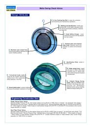
There are some common parts innate to butterfly valves regardless<br />
of its design, brand or materials of construction as follows:<br />
A Body; this is the main framework of the valve which houses the<br />
moving components of the same. It is made of metal and can be of<br />
diverse styles as mentioned above.<br />
B Liner; it is a rubber or plastic circular seat inserted into the body<br />
inner part and can be either vulcanised or made of an insert. The<br />
vulcanised type cannot be removed once assembled whilst the insert<br />
can be replaced at any time. The liner provides the required<br />
tightness to the valve.<br />
C Shaft; it is the rod that drives the disc by rotation. It can be made<br />
of two piece rod (without pin) or a single piece rod (with pin) depending<br />
the way to assemble and disassemble it.<br />
D Disc; It is the plate which is guided by the shaft and blocks or<br />
allows the fluid to pass. It is the closing element of the valve.<br />
E Packing; set of soft goods that provides the atmospheric integrity<br />
to the valve. Usually are provided with a shaft packing in the upper<br />
part and the bottom bush in the lower part.<br />
F Notch plate; it is the metal position indicator and gear locking<br />
fi x on top of the valve neck where the actuator is supported. The<br />
function is locking the actuator in intermediate positions if needed.<br />
G Actuation; it is the component which actions the valve, it may be<br />
a hand lever; usually used for quick action and standard sizes; a<br />
worm gear box; used for slower action and large valve sizes; pneumatic,<br />
electric pr hydraulic actuators; for remote and continuous<br />
operations.<br />
H Name Plate; not innate to the valve design but of equal importance<br />
as it is providing the user all design and working parameters of<br />
the valve. It is normally affixed onto the valve front neck by riveted<br />
aluminium plate.<br />
B<br />
F<br />
H<br />
C<br />
G<br />
E<br />
A<br />
D<br />
Basic Operating and Maintenance Guidelines.<br />
Butterfl y Valves are bidirectional and can also be installed in whatever position being along the horizontal or vertical pipe work<br />
axis. It is recommended to fl ush the pipe work system out with valves fully open before start up. Valves thermal insulation can be<br />
easily carried out thanks to the extended neck design as standard, this makes easier the task to insulate the valves by means<br />
of the aluminium rigid material.<br />
Replaceable seat Butterfl y valves are relatively easy to maintain. The resilient seat is held in place by mechanical means, and<br />
neither bonding nor cementing is necessary, Because the seat is replaceable, the valve seat does not require lapping, grinding,<br />
or machine work. The job can be done at the plant operator by having the adequate tools to carry out this service.<br />
If, otherwise, valves are of vulcanised seat, these have no possibility to be serviced although the low cost of the valve would not<br />
suggest to do it.<br />
The actuation is quickly dismounted and replaced if needed. All valve top works are normally designed to comply with ISO 5211<br />
standard that guides the dimensions to be followed in order to adapt actuators with full versatility.<br />
This engineering manual illustrates all the UNIVAL® range of butterfl y valves, one of the largest portfolios of butterfl y valves presently available<br />
for isolating and regulating duties. It is comprehensive of diverse styles and materials of construction and offers an in-deep study to the superb<br />
design and performance availed by the more than a million units installed all over the world.<br />
Data subject to change without prior notice<br />
11
Unival® BUTTERFLY VALVES<br />
Flow Data<br />
Data Sheets Manual<br />
A valve fl ow coeffi cient represents the standard flow rate which flows through the<br />
valve at a given opening, referred to pre-established conditions:<br />
* Kv value is the volume of water at 20ºC, in cubic meters per hour (m3/h), that will<br />
flow through the valve at a static pressure drop of 1 bar across the valve<br />
* Cv value is the volume of water at 60ºF, in gallons per minute (gpm), that will flow<br />
through the valve at a static pressure drop of 1 psi across the valve<br />
Conversion from Kv to Cv can be roughly calculated by means of the following expression:<br />
Cv = Kv x 1,17<br />
Flow rate through the valve with other liquids can be calculated with the following<br />
expressions (for gases please consult us)<br />
Kv = q (SG / dp)1/2<br />
where<br />
q = water fl ow (m3/h)<br />
SG = specifi c gravity (1 for water)<br />
dp = pressure drop (bar)<br />
Cv = q (SG / dp)1/2<br />
where<br />
q = water fl ow (US gallons per minute)<br />
SG = specifi c gravity (1 for water)<br />
dp = pressure drop (psi)<br />
It is common practice to size the valves on the basis of pipe DN for on off application.<br />
Nevertheless, Butterfl y Valves used for control purpose should be calculated on the<br />
basis of operating conditions.<br />
First step is to calculate the Kv values for the different working conditions and then<br />
choose the DN with such Kv values in the region of 20º to 70º valve opening angle.<br />
As a general guideline, fl ow velocities should under certain limits, so as to avoid<br />
valve excessive noise, vibration and cavitation:<br />
Liquids: < 4,5 m/s; Gases: < 100 m/s<br />
<strong>COMEVAL</strong> Technical Department is at your disposal to help you sizing your system.<br />
Data subject to change without prior notice<br />
12
Unival® BUTTERFLY VALVES<br />
Flow Data<br />
Data Sheets Manual<br />
Size<br />
Opening Angle of the Valve<br />
DN 10º 20º 30º 40º 50º 60º 70º 80º 90º<br />
25 - - 1,5 5 8,3 14 22 33 36<br />
32 - 0,8 1,7 5,3 9,5 16 25 37 41<br />
40 - 1,5 3,5 8 14 23 37 55 61<br />
50 - 2,5 7 14 24 40 64 95 105<br />
65 - 5 11 23 40 67 107 159 176<br />
80 - 9 20 35 61 101 161 240 265<br />
100 - 16 38 78 137 226 360 538 594<br />
125 0,5 26 69 129 219 361 576 860 950<br />
150 0,8 44 105 205 373 617 983 1468 1622<br />
200 1,3 82 205 387 680 1124 1792 2676 2957<br />
250 2,1 138 345 669 1084 1791 2855 4263 4711<br />
300 3,7 210 534 1028 1639 2707 4318 6449 7126<br />
350 5,5 305 750 1326 2347 3878 6184 9236 10205<br />
400 7,4 388 935 1813 3208 5301 8454 12625 13950<br />
450 9,7 550 1212 2370 4193 6929 11049 16500 18232<br />
500 13 658 1595 2981 5275 8716 13900 20758 22937<br />
600 20 962 2246 4431 7919 13083 20864 31158 34429<br />
700 55 1233 2725 5105 9022 14906 23770 35499 39225<br />
800 135 1719 3394 6367 10338 17081 27239 40905 44950<br />
900 180 2475 4731 8631 13691 22620 36072 54165 59525<br />
1000 250 3342 6443 11752 18642 30800 49116 73755 81050<br />
1200 320 4715 8643 15155 24198 39980 63757 95741 105210<br />
Kv<br />
Disc Opening<br />
Data subject to change without prior notice<br />
13
Unival® BUTTERFLY VALVES<br />
Seats - Application Guide<br />
Data Sheets Manual<br />
NBR Butadiene Acrylonitrile (-20ºC) -10ºC ... 75ºC (90ºC)<br />
Lubricating oil, cutting oils, fuel oils, animal and vegetable oils, aviation kerosen, LPG, oily air. Generally resistant to oils and<br />
solvents.<br />
Limited resistance to ozone and wheather.<br />
EPDM Ethylene Propylene Diene (-20ºC) -5ºC ... 120ºC (130ºC)<br />
Salts in water, diluted acids, alkaline solutions, ester, ketones, alcohols, glycols, hot water, intermittent steam, sterilisation<br />
Good resistance to ozone and wheather.<br />
It is attacked by hydrocarbon solutions, chlorinated hydrocarbons and other petroleum based oils.<br />
Viton (FPM) Vinylidenefluoride-hexafluoro-propyleneco-polymer (-20ºC) -10ºC ... 150ºC (180º)<br />
Strong and weak mineral acids, aliphatic hydrocarbons, chlorine gas, oils, aliphatic acids, phosporic acids, ozone, certain<br />
aromatic solvents<br />
Not suitable for hot water, steam and dry heat.<br />
Hypalon (CSM) Chlorosulfonated polyethylene (-20ºC) -10ºC ... 110ºC (130ºC)<br />
Good chlorine and weather resistance. Low resistance to oil and fats<br />
Silicone (-40ºC) -20ºC ... 170ºC (190ºC)<br />
Good wheather resistance. Recommended for hot air applications. Not resistant to mineral oils. Moderate mechanical properties.<br />
PTFE PTFE/EPDM (-20ºC) -5ºC ... 110ºC (120ºC) - PTFE/NBR (-20ºC) -10ºC ... 80ºC (90ºC)<br />
Excellent resistance to chemicals or biopharmaceuticals, strong acids and solvents, alkalies and salts in water. Excellent<br />
resistance to weather.<br />
FEP -20ºC ... 120ºC (130ºC)<br />
Similar properties to PTFE but more translucent and with lower porosity, so most suitable for concentrated mineral acids,<br />
aromatic, aliphatic and chlorinated solvents.<br />
PFA -20ºC ... 180ºC (190ºC)<br />
Similar to FEP but with smoother surface texture and for higher continuos service temperatures.<br />
Breaf Peak Temperature<br />
Working Temperature<br />
Temperature ranges given just for reference.<br />
Body pressure-temperature rating also to be considered for valve selection.<br />
Please consult our Technical Department for a particular application.<br />
Data subject to change without prior notice<br />
14
Unival® BUTTERFLY VALVES<br />
Valve Coding<br />
Data Sheets Manual<br />
V F 7 0 0 P X/Y X/Y X/Y 0 0 0 5 0<br />
VF = UNIVAL<br />
BUTTERFLY VALVE<br />
IDENTIFICATION<br />
050 = Valve size DN50<br />
100 = Valve size DN100<br />
700 = WAFER TYPE CARTRIDGE SEAT<br />
701 = WAFER TYPE WITH EDGE-BOOT SEAT<br />
751 = LUG TYPE WITH EDGE-BOOT SEAT<br />
750 = LUG TYPE WITH BACK SEAT<br />
760 = GROOVE END TYPE<br />
790 = DOUBLE FLANGE TYPE<br />
7U = U-TYPE<br />
791 = DOUBLE ECCENTRIC TYPE<br />
00 Special Requirements<br />
P = WITH LEVER<br />
R = WITH WORM GEAR<br />
B = BARE SHAFT<br />
XXX<br />
G* = DISC IN DUCTILE IRON GGG40<br />
I* = DISC IN ST. STEEL AISI316<br />
B* = DISC IN AL-BZ<br />
F* = DISC COATED FEP<br />
P* = DISC COATED PFA<br />
*E* = SEAT IN EPDM<br />
*N* = SEAT IN NBR<br />
*V* = SEAT IN VITON<br />
*S* = SEAT IN SILICON<br />
*T* = SEAT IN PTFE<br />
*F* = SEAT IN FEP<br />
*P* = SEAT IN PFA<br />
*H* = SEAT IN HYPALON<br />
YYY<br />
G* = BODY IN DI GGG40<br />
A* = BODY IN CS WCB<br />
I* = BODY IN ST.ST. AISI316<br />
*G* = DISC IN DI GGG40 NICKEL PLATED<br />
*I* = DISC IN ST.ST. AISI316<br />
*B* = DISC IN AL-BZ<br />
*F* = DISC COATED FEP<br />
*P* = DISC COATED PFA<br />
*N = SEAT IN NBR *T =SEAT IN PTFE<br />
*V = SEAT IN VITON *F = SEAT IN FEP<br />
*S = SEAT IN SILICON *P = SEAT IN PFA<br />
*H = HYPALON<br />
*0 = BODY IN GG25<br />
Data subject to change without prior notice<br />
15
Unival® BUTTERFLY VALVES<br />
Attributes of Design - Wafer Series VF700<br />
Data Sheets Manual<br />
Notch Plate; with position indicator and gear<br />
locking, lever locking in intermediate position<br />
when needed.<br />
Top Mounting Arrangement; top flange to suit<br />
actuators as per ISO 5211 standard, square<br />
stem with bevelled edges to ease actuator<br />
coupling.<br />
Marking according to EN19, with name plate including<br />
CE marking, valve identifi cation and serial number for full<br />
traceability purpose.<br />
Rugged and light Lever; Ergonomic design,<br />
trigger style with covered spring.<br />
Prepared for padlocking application to avoid<br />
undesired operation.<br />
O-ring safety shaft sealing, with<br />
retaining washer to ensure proper<br />
working under pressure.<br />
Finely Machined Disc Edges with final<br />
polishing, provides tight valve sealing<br />
and ensures minimum operating torque<br />
and longer duration of the rubber liner.<br />
Centring eyelets; series 700 provide<br />
full passing bolts to assemble between<br />
counter fl anges ISO / DIN / EN 1092<br />
PN10/16 and ASA 150.<br />
Extended Valve Neck<br />
enables thermal isolation<br />
in heating plants.<br />
One Piece Shaft; solid, stainless steel<br />
corrosion resistant. One piece<br />
through design ensures dependability<br />
and positive disc positioning.<br />
Precise Shaft Guiding System; the<br />
shaft is carried in four estrategically<br />
placed bushings preventing deflection<br />
under pressure, thus ensuring<br />
optimal guidance, positive location<br />
and long life. PTFE bushing accurate<br />
guidance reduces torque and isolates<br />
the stem from valve body, preventing<br />
stem corrosion.<br />
Precision Machined Body; thus<br />
the liner with shaft location can<br />
be accurately positioned to ensure<br />
minimal operation wear<br />
and extended life span.<br />
Epoxy powder paint protection<br />
Replaceable seat liner with phenolic backed seat,<br />
up to DN400, aluminium backed seat DN450 and<br />
above,non-collapsible, stretch resistant, blow out<br />
proof, allows softer rubber liners, which ensure<br />
longer life span and better tightness.<br />
Liner is profi led to ensure a tight shut off sealing<br />
when installing between flanges (pressure activated<br />
system), thus no need to provide gaskets<br />
between valve and counter flanges.<br />
Shaft-Disc threaded union standard up to<br />
DN300: disc offers clean surface against<br />
the fluid, without union pins source of<br />
corrosion and turbulences in small sizes.<br />
Data subject to change without prior notice<br />
16
Unival® BUTTERFLY VALVES<br />
Parts and Materials - Wafer Series VF700<br />
Data Sheets Manual<br />
Nº Part Material<br />
1 BODY Cast Iron EN-JL1040 (GG25) / Ductile Iron EN-JS1030 (GGG40) / St. Steel A351 CF8M / Carbon Steel A216 WCB<br />
2 DISC Nickel Plated Ductile Iron EN-JS1030 (GGG40) / St. Steel CF8M / Al-Bronze / FEP or PFA Coated / Uranus UB6<br />
3 LINER NBR / EPDM / Viton / Hypalon / Silicon / PTFE / FEP / PFA<br />
4 STEM St. Steel AISI 416<br />
5 O-RING EPDM, NBR<br />
6 BUSHINGS PTFE<br />
7 WASHER Steel<br />
8 CIRCLIP Steel<br />
9 NOTCH PLATE Aluminium<br />
10 HAND LEVER Alumminium / Ductile Iron<br />
11 STUDS Steel<br />
13 WASHERS Steel<br />
14 NUT Steel<br />
15 WORM GEAR Ductile Iron<br />
Data subject to change without prior notice<br />
17
Unival® BUTTERFLY VALVES<br />
Dimensions - Wafer Series VF700 DN32-600<br />
Data Sheets Manual<br />
DN<br />
MAIN DIMENSIONS COUPLING DETAIL LEVER WORM GEAR Weight<br />
A B ØC D E R ØG ØJ ØM T L F S Z ØK (kg)<br />
32 121 57 73 33 32 7x7 65 50 7 74 200 156 42 116 150 2,0<br />
40 130 61 82 33 32 9x9 65 50 7 74 200 156 42 116 150 6,0<br />
50 137 77 95 43 32 9x9 65 50 7 74 200 156 42 116 150 6,5<br />
65 142 88 109 46 32 9x9 65 50 7 74 200 156 42 116 150 7,0<br />
80 158 95 127 46 32 9x9 65 50 7 74 200 156 42 116 150 8,0<br />
100 180 107 152 52 32 11x11 65 50 7 74 200 156 42 116 150 9,0<br />
125 192 122 180 56 42 14x14 90 70 9 79 278 156 42 168 250 10,5<br />
150 215 144 207 56 42 14x14 90 70 9 79 278 156 42 168 250 12,5<br />
200 242 171 260 60 30 17x17 125 102 11 40 355 223 70 195 300 21,5<br />
250 280 205 315 68 32 22x22 150 125 13 40 507 223 70 195 300 37,5<br />
300 310 235 370 78 32 27x27 150 125 13 37 507 223 80 195 300 45,5<br />
350 337 259 418 78 45 27x27 150 125 14 - - 223 80 195 300 54,5<br />
400 358 304 470 102 50 27x27 150 125 14 - - 270 114 208 300 90,0<br />
450 380 365 525 114 50 30x30 210 165 22 - - 270 114 258 300 107,5<br />
500 427 392 575 127 65 30x30 210 165 22 - - 339 125 222 300 156,0<br />
600 617 514 693 154 70 40x40 300 210 22 - - 339 125 222 300 231,5<br />
Dimensions are expressed in mm, and subjected to manufacturing tolerances. Data can be altered without notice by our Design Department for the product benefi t.<br />
Manufacture Design Standards:<br />
Harmonised Standard EN 593<br />
QA certifi ed to ISO 9001:2000<br />
According to Pressure Equipment Directive PED 97/23/EC by a recognised Notify body<br />
Testing standards EN12266-1 / API 598<br />
Marking according to EN 19<br />
Face to face dimensions according to EN558-1 Series 20<br />
Body end connections wafer type to be installed between flanges<br />
DN32-600: EN 1092-1/2 PN10/16 and ASA150; other connections available on request<br />
Epoxy painted Blue RAL5002<br />
Operating Parameters:<br />
Working pressure: 0...16 bar-g DN25-300; 0...10 bar-g DN350-600<br />
Working temperature: according to sealing material<br />
See Engineering Data for complete overview of operating parameters<br />
Main Applications:Water, oil, compressed air, low pressure steam, etc.<br />
Data subject to change without prior notice<br />
18
Unival® BUTTERFLY VALVES<br />
Dimensions - Wafer Series VF700 DN700-1200<br />
Data Sheets Manual<br />
DN<br />
MAIN DIMENSIONS COUPLING DETAIL PN10 CONNECTION WORM GEAR Weight<br />
A B D E ØR ØG ØJ ØN ØP M nXØd F S Z ØK (kg)<br />
700 629 539 165 80 63,35 300 254 18 840 M27 24xØ30 357 243 382 435 372<br />
800 666 608 190 80 63,35 300 254 18 950 M30 24xØ33 357 243 382 435 655<br />
900 722 667 205 118 75 300 254 18 1050 M30 28xØ33 410 278 476 435 769<br />
1000 800 732 218 142 85 300 254 18 1160 M33 28xØ36 410 278 476 435 943<br />
1200 940 844 276 150 105 300 288 22 1380 M36 32xØ40 - - - - 1472<br />
Dimensions are expressed in mm, and subjected to manufacturing tolerances. Data can be altered without notice by our Design Department for the product benefi t.<br />
Manufacture Design Standards:<br />
Harmonised Standard EN 593<br />
QA certifi ed to ISO 9001:2000<br />
According to Pressure Equipment Directive PED 97/23/EC by a recognised Notify body<br />
Testing standards EN12266-1 / API 598<br />
Marking according to EN 19<br />
Face to face dimensions according to EN558-1 Series 20<br />
Body end connections wafer type to be installed between flanges<br />
DN700-1200: EN 1091-1/2 PN10 or PN16 or ASA150 other connections available on request<br />
Epoxy painted Blue RAL5002<br />
Operating Parameters:<br />
Working pressure: 0...10 bar-g<br />
Working temperature: according to sealing material<br />
See Engineering Data for complete overview of operating parameters<br />
Main Applications:Water, oil, compressed air, low pressure steam, etc.<br />
Data subject to change without prior notice<br />
19
Unival® BUTTERFLY VALVES<br />
Attributes of Design - Wafer Series VF701<br />
Data Sheets Manual<br />
Notch Plate; with position indicator and gear<br />
locking, lever locking in intermediate position<br />
when needed.<br />
Top Mounting Arrangement; top flange to suit<br />
actuators as per ISO 5211 standard, square<br />
stem with bevelled edges to ease actuator<br />
coupling.<br />
Marking according to EN19, with name plate including<br />
CE marking, valve identifi cation and serial number for full<br />
traceability purpose.<br />
Rugged and light Lever; Ergonomic design,<br />
trigger style with covered spring.<br />
Prepared for padlocking application to avoid<br />
undesired operation.<br />
One Piece Shaft; solid, stainless steel<br />
corrosion resistant. One piece<br />
through design ensures dependability<br />
and positive disc positioning.<br />
O-ring safety shaft sealing,<br />
with retaining washer to ensure<br />
proper working under<br />
pressure.<br />
Extended Valve Neck<br />
enables thermal isolation<br />
in heating plants.<br />
Finely Machined Disc Edges with fi nal<br />
polishing, provides tight valve sealing<br />
and ensures minimum operating torque<br />
and longer duration of the rubber liner.<br />
Precise Shaft Guiding System; the<br />
shaft is carried in four estrategically<br />
placed bushings preventing deflection<br />
under pressure, thus ensuring<br />
optimal guidance, positive location<br />
and long life. PTFE bushing accurate<br />
guidance reduces torque and isolates<br />
the stem from valve body, preventing<br />
stem corrosion.<br />
Precision Machined Body; thus<br />
the liner with shaft location can<br />
be accurately positioned to ensure<br />
minimal operation wear<br />
and extended life span.<br />
Epoxy powder paint protection<br />
Centring eyelets; series 700 provide<br />
full passing bolts to assemble between<br />
counter fl anges ISO / DIN / EN 1092<br />
PN10/16 and ASA 150.<br />
Replaceable seat liner edge boot seat design,<br />
replaceable lined without need for special tools.<br />
Data subject to change without prior notice<br />
Shaft-Disc threaded union standard up to<br />
DN300: disc offers clean surface against<br />
the fluid, without union pins source of<br />
corrosion and turbulences in small sizes.<br />
20
Unival® BUTTERFLY VALVES<br />
Parts and Materials - Wafer Series VF701<br />
Data Sheets Manual<br />
Nº Part Material<br />
1 BODY Cast Iron EN-JL1040 (GG25) / Ductile Iron EN-JS1030 (GGG40) / St. Steel A351 CF8M / Carbon Steel A216 WCB<br />
2 DISC Nickel Plated Ductile Iron EN-JS1030 (GGG40) / St. Steel CF8M / Al-Bronze / FEP or PFA Coated / Uranus UB6<br />
3 LINER NBR / EPDM / Viton / Hypalon / Silicon / PTFE / FEP / PFA<br />
4 STEM St. Steel AISI 416<br />
5 O-RING EPDM, NBR, Viton<br />
6 BUSHINGS PTFE<br />
7 WASHER Steel<br />
8 CIRCLIP Steel<br />
9 NOTCH PLATE Aluminium<br />
10 HAND LEVER Alumminium / Ductile Iron<br />
11 STUDS Steel<br />
13-14 WASHERS Steel<br />
15 WORM GEAR Ductile Iron<br />
Data subject to change without prior notice<br />
21
Unival® BUTTERFLY VALVES<br />
Dimensions - Wafer Series VF701 DN40-300<br />
Data Sheets Manual<br />
DN<br />
MAIN DIMENSIONS COUPLING DETAIL LEVER WORM GEAR Weight<br />
A B D E R ØG ØJ ØM T L F S Z ØK (kg)<br />
40 143 55 33 32,5 9x9 65 50 8 60 190 155 45 125 150 6,0<br />
50 143 55 43 32,5 9x9 65 50 8 60 190 155 45 125 150 6,5<br />
65 155 64 46 32,5 9x9 65 50 8 60 190 155 45 125 150 7,0<br />
80 162 72 46 32,5 9x9 65 50 8 60 190 155 45 125 150 8,0<br />
100 183,8 90 52 42,5 11x11 90 70 10 70 220 155 45 125 150 9,0<br />
125 197 101 56 42,5 14x14 90 70 10 70 220 155 45 125 150 10,5<br />
150 210 114 56 42,5 14x14 90 70 10 70 220 155 45 125 150 12,5<br />
200 240 145 60 42,,5 17x17 125 102 12 31 360 250 63 205 300 21,5<br />
250 286 178 68 37 22x22 125 102 12 31 360 250 63 205 300 37,5<br />
300 309 204 78 37 22x22 125 102 12 35 498 250 80 204 300 45,5<br />
Dimensions are expressed in mm, and subjected to manufacturing tolerances. Data can be altered without notice by our Design Department for the product benefi t.<br />
Manufacture Design Standards:<br />
Edge boot seat design<br />
Harmonised Standard EN 593<br />
QA certifi ed to ISO 9001:2000<br />
According to Pressure Equipment Directive PED 97/23/EC by a recognised Notify body<br />
Testing standards EN12266-1 / API 598<br />
Marking according to EN 19<br />
Face to face dimensions according to EN558-1 Series 20<br />
Body end connections wafer type to be installed between flanges<br />
DN40-300: EN 1092-1/2 PN10/16 and ASA150; other connections available on request<br />
Epoxy painted Blue RAL5005<br />
Operating Parameters:<br />
Working pressure: PN16 0...16 bar-g; PN10 0...10 bar-g<br />
Working temperature: according to sealing material<br />
See Engineering Data for complete overview of operating parameters<br />
Main Applications:Water, oil, compressed air, low pressure steam, etc.<br />
Data subject to change without prior notice<br />
22
Unival® BUTTERFLY VALVES<br />
Dimensions - Wafer Series VF701 DN350-600<br />
Data Sheets Manual<br />
DN<br />
MAIN DIMENSIONS COUPLING DETAIL WORM GEAR Weight<br />
A B D E R ØG ØJ ØM F S Z ØK (kg)<br />
350 368 267 78 45 22x22 125 102 12 227 80 205 300 55<br />
400 400 299 102 51,2 22x22 175 140 18 278 179 220 300 90<br />
450 422 318 114 51,2 27x27 175 140 18 278 179 220 300 108<br />
500 480 348 127 64,2 27x27 175 140 18 278 179 220 300 156<br />
600 562 444 154 70,2 36x36 210 165 22 304 198 240 300 232<br />
Dimensions are expressed in mm, and subjected to manufacturing tolerances. Data can be altered without notice by our Design Department for the product benefi t.<br />
Manufacture Design Standards:<br />
Edge boot seat design<br />
Harmonised Standard EN 593<br />
QA certifi ed to ISO 9001:2000<br />
According to Pressure Equipment Directive PED 97/23/EC by a recognised Notify body<br />
Testing standards EN12266-1 / API 598<br />
Marking according to EN 19<br />
Face to face dimensions according to EN558-1 Series 20<br />
Body end connections wafer type to be installed between flanges<br />
DN350-600: EN 1092-1/2 PN10/16 and ASA150; other connections available on request<br />
Epoxy painted Blue RAL5005<br />
Operating Parameters:<br />
Working pressure: PN16 0...16 bar-g; PN10 0...10 bar-g<br />
Working temperature: according to sealing material<br />
See Engineering Data for complete overview of operating parameters<br />
Main Applications:Water, oil, compressed air, low pressure steam, etc.<br />
Data subject to change without prior notice<br />
23
Unival® BUTTERFLY VALVES<br />
Attributes of Design - Lug Series VF750<br />
Data Sheets Manual<br />
Notch Plate; with position indicator and gear<br />
locking, lever locking in intermediate position<br />
when needed.<br />
Top Mounting Arrangement; top flange to suit<br />
actuators as per ISO 5211 standard, square<br />
stem with bevelled edges to ease actuator<br />
coupling.<br />
Marking according to EN19, with name plate including<br />
CE marking, valve identifi cation and serial number for full<br />
traceability purpose.<br />
Rugged and light Lever; Ergonomic design,<br />
trigger style with covered spring.<br />
Prepared for padlocking application to avoid<br />
undesired operation.<br />
O-ring safety shaft sealing, with<br />
retaining washer to ensure proper<br />
working under pressure.<br />
Finely Machined Disc Edges with final<br />
polishing, provides tight valve sealing<br />
and ensures minimum operating torque<br />
and longer duration of the rubber liner.<br />
Threaded eyelets; the choice for pipe<br />
ends. Available for several DIN / ASA<br />
counterfl anges.<br />
Extended Valve Neck<br />
enables thermal isolation<br />
in heating plants.<br />
One Piece Shaft; solid, stainless steel<br />
corrosion resistant. One piece<br />
through design ensures dependability<br />
and positive disc positioning.<br />
Precise Shaft Guiding System; the<br />
shaft is carried in four estrategically<br />
placed bushings preventing defl ection<br />
under pressure, thus ensuring<br />
optimal guidance, positive location<br />
and long life. PTFE bushing accurate<br />
guidance reduces torque and<br />
isolates the stem from valve body,<br />
preventing stem corrosion.<br />
Precision Machined Body; thus<br />
the liner with shaft location can<br />
be accurately positioned to ensure<br />
minimal operation wear<br />
and extended life span.<br />
Epoxy powder paint protection<br />
Replaceable seat liner with phenolic backed seat,<br />
non-collapsible, stretch resistant, blow out proof,<br />
allows softer rubber liners, which ensure longer<br />
life span and better tightness.<br />
Liner is profi led to ensure a tight shut off sealing<br />
when installing between fl anges (pressure activated<br />
system), thus no need to provide gaskets between<br />
valve and counter fl anges.<br />
Shaft-Disc threaded union standard up to<br />
DN300: disc offers clean surface against<br />
the fluid, without union pins source of<br />
corrosion and turbulences in small sizes.<br />
Data subject to change without prior notice<br />
24
Unival® BUTTERFLY VALVES<br />
Parts and Materials - Lug eries VF750<br />
Data Sheets Manual<br />
Nº Part Material<br />
1 BODY Cast Iron EN-JL1040 (GG25) / Ductile Iron EN-JS1030 (GGG40) / St. Steel A351 CF8M / Carbon Steel A216 WCB<br />
2 DISC Nickel Plated Ductile Iron EN-JS1030 (GGG40) / St. Steel CF8M / Al-Bronze / FEP or PFA Coated / Uranus UB6<br />
3 LINER NBR / EPDM / Viton / Hypalon / Silicon / PTFE / FEP / PFA<br />
4 STEM St. Steel AISI 416<br />
5 O-RING EPDM, NBR<br />
6 BUSHINGS PTFE<br />
7 WASHER Steel<br />
8 CIRCLIP Steel<br />
9 NOTCH PLATE Aluminium<br />
10 HAND LEVER Alumminium / Ductile Iron<br />
11 STUDS Steel<br />
13 WASHERS Steel<br />
14 NUT Steel<br />
15 WORM GEAR Ductile Iron<br />
Data subject to change without prior notice<br />
25
Unival® BUTTERFLY VALVES<br />
Dimensions - Lug Series VF750<br />
Data Sheets Manual<br />
LUG CONNECTION<br />
DN<br />
MAIN DIMENSIONS<br />
COUPLING DETAIL<br />
LEVER & WORM GEAR<br />
Weight<br />
PN10<br />
PN16<br />
(kg)<br />
A B ØC D E R ØG ØJ ØM ØP nxØd ØP nxØd T L F S Z ØK<br />
25 121 53 65 33 32 7x7 65 50 7 85 4xM12 85 4xM12 74 200 156 42 116 150 2,5<br />
32 121 57 73 33 32 7x7 65 50 7 100 4xM16 100 4xM16 74 200 156 42 116 150 2,5<br />
40 130 61 82 33 32 9x9 65 50 7 110 4xM16 110 4xM16 74 200 156 42 116 150 7,0<br />
50 136,5 77 95 43 32 9x9 65 50 7 125 4xM16 125 4xM16 74 200 156 42 116 150 7,5<br />
65 142 87,5 109 46 32 9x9 65 50 7 145 4xM16 145 4xM16 74 200 156 42 116 150 8,5<br />
80 158 95 127 46 32 9x9 65 50 7 160 8xM16 160 8xM16 74 200 156 42 116 150 9,5<br />
100 180 107 152 52 32 11x11 65 50 7 180 8xM16 180 8xM16 47 200 156 42 116 150 11,0<br />
125 192 121,5 180 56 42 14x14 90 70 9 210 8xM16 210 8xM16 79 278 156 42 168 250 13,5<br />
150 215 144 207 56 42 14x14 90 70 9 240 8xM20 240 8xM20 79 278 156 42 168 250 15,5<br />
200 241,5 171 260 60 30 17x17 125 102 11 295 8xM20 295 12xM20 40 355 223 70 195 300 25,0<br />
250 280 205 315 68 32 22x22 150 125 13 350 12xM20 355 12xM24 40 507 223 70 195 300 45,0<br />
300 310 235 370 78 32 27x27 150 125 13 400 12xM20 410 12xM24 37 507 223 80 195 300 57,0<br />
350 337 258,5 418 78 45 27x27 150 125 14 460 16xM20 470 16xM24 - - 223 80 195 300 79,5<br />
400 357,3 303,3 470 102 50 27x27 150 125 14 515 16xM24 525 16xM27 - - 270 114 208 300 123,0<br />
450 380 365 525 114 50 30x30 210 165 22 565 20xM24 585 20xM27 - - 270 114 258 300 155,0<br />
500 426,3 392 575 127 65 30x30 210 165 22 620 20xM24 650 20xM30 - - 339 125 222 300 228,5<br />
600 616,5 513,5 693 154 70 40x40 300 210 22 725 20xM27 770 20xM33 - - 339 125 222 300 309,0<br />
Dimensions are expressed in mm, and subjected to manufacturing tolerances. Data can be altered without notice by our Design Department for the product benefi t.<br />
Manufacture Design Standards:<br />
Harmonised Standard EN 593<br />
QA certifi ed to ISO 9001:2000<br />
According to Pressure Equipment Directive PED 97/23/EC by a recognised Notify body<br />
Testing standards EN12266-1 / API 598<br />
Marking according to EN 19<br />
Face to face dimensions according to EN558-1 Series 20<br />
Body end connections lug type to be installed between flanges<br />
EN1092-1/2 PN16 DN25-300, PN10 DN350-600. Other connections available on request<br />
Epoxy painted Blue RAL5002<br />
Operating Parameters:<br />
Working pressure: 0...16 bar-g DN25-300; 0...10 bar-g DN350-600<br />
Working temperature: according to sealing material<br />
See Engineering Data for complete overview of operating parameters<br />
Main Applications:Water, oil, compressed air, low pressure steam, etc.<br />
Data subject to change without prior notice<br />
26
Unival® BUTTERFLY VALVES<br />
Assembling Set<br />
Data Sheets Manual<br />
UNI VF700 (wafer) PN10<br />
DN<br />
Bolts with nuts Stay bolts with nuts Flanges PN10*<br />
Quantity Size Quantity Size Quantity<br />
40 4 M16x85 - - 2<br />
50 4 M16x100 - - 2<br />
65 4 M16x110 - - 2<br />
80 8 M16x110 - - 2<br />
100 8 M16x110 - - 2<br />
125 8 M16x120 - - 2<br />
150 8 M20x125 - - 2<br />
200 8 M20x140 - - 2<br />
250 12 M20x150 - - 2<br />
300 12 M20x160 - - 2<br />
350 16 M20x160 - - 2<br />
400 16 M24x200 - - 2<br />
450 20 M24x220 - - 2<br />
500 20 M24x230 - - 2<br />
600 20 M27x270 - - 2<br />
700 8 M27x70 20/40 M27x310 2<br />
800 8 M30x80 20/40 M30x340 2<br />
900 8 M30x80 24/48 M30x360 2<br />
1000 8 M33x80 24/48 M33x380 2<br />
*Welding neck flanges EN1092-1 11 PN10 (DIN2632)<br />
UNI VF700 (wafer) PN16<br />
DN<br />
Bolts with nuts Stay bolts with nuts Flanges PN16*<br />
Quantity Size Quantity Size Quantity<br />
40 4 M16x90 - - 2<br />
50 4 M16x100 - - 2<br />
65 4 M16x110 - - 2<br />
80 8 M16x110 - - 2<br />
100 8 M16x120 - - 2<br />
125 8 M16x130 - - 2<br />
150 8 M20x140 - - 2<br />
200 12 M20x140 - - 2<br />
250 12 M24x160 - - 2<br />
300 12 M24x180 - - 2<br />
350 16 M24x180 - - 2<br />
400 16 M27x220 - - 2<br />
450 20 M27x230 - - 2<br />
500 20 M30x250 - - 2<br />
600 20 M33x300 - - 2<br />
700 8 M33x90 20/40 M33x340 2<br />
800 8 M36x90 20/40 M36x370 2<br />
900 8 M36x90 24/48 M36x390 2<br />
1000 8 M39x100 24/48 M39x420 2<br />
*Welding neck fl anges EN1092-1 11 PN16 (DIN2633)<br />
UNI VF750 (lug) PN10<br />
DN<br />
Bolts<br />
Flanges PN10*<br />
Quantity Size Quantity<br />
25 8 M12x30 2<br />
32 8 M16x30 2<br />
40 8 M16x30 2<br />
50 8 M16x35 2<br />
65 8 M16x40 2<br />
80 16 M16x40 2<br />
100 16 M16x40 2<br />
125 16 M16x45 2<br />
150 16 M20x45 2<br />
200 16 M20x50 2<br />
250 24 M20x55 2<br />
300 24 M20x60 2<br />
350 32 M20x60 2<br />
400 32 M24x70 2<br />
450 40 M24x70 2<br />
500 40 M24x80 2<br />
600 40 M27x80 2<br />
*Welding neck flanges EN1092-1 11 PN10 (DIN2632)<br />
UNI VF750 (lug) PN16<br />
DN<br />
Bolts<br />
Flanges PN16*<br />
Quantity Size Quantity<br />
25 8 M12x30 2<br />
32 8 M16x30 2<br />
40 8 M16x30 2<br />
50 8 M16x35 2<br />
65 16 M16x40 2<br />
80 16 M16x40 2<br />
100 16 M16x40 2<br />
125 16 M16x45 2<br />
150 16 M20x45 2<br />
200 24 M20x50 2<br />
250 24 M24x55 2<br />
300 24 M24x60 2<br />
350 32 M24x60 2<br />
400 32 M27x75 2<br />
450 40 M27x80 2<br />
500 40 M30x90 2<br />
600 40 M33x90 2<br />
*Welding neck fl anges EN1092-1 11 PN16 (DIN2633)<br />
Data subject to change without prior notice<br />
27
Unival® BUTTERFLY VALVES<br />
Attributes of Design - U Type Series VF7U<br />
Data Sheets Manual<br />
Notch Plate; with position indicator and gear<br />
locking, lever locking in intermediate position<br />
when needed.<br />
Top Mounting Arrangement; top flange to suit<br />
actuators as per ISO 5211 standard, square<br />
stem with bevelled edges to ease actuator<br />
coupling.<br />
Marking according to EN19, with name plate including<br />
CE marking, valve identifi cation and serial number for full<br />
traceability purpose.<br />
Rugged and light Lever; Ergonomic design,<br />
trigger style with covered spring.<br />
Prepared for padlocking application to avoid<br />
undesired operation.<br />
O-ring safety shaft sealing, with<br />
retaining washer to ensure proper<br />
working under pressure.<br />
Finely Machined Disc Edges with final<br />
polishing, provides tight valve sealing<br />
and ensures minimum operating torque<br />
and longer duration of the rubber liner.<br />
Flanged ends with U-Shape body.<br />
Short pattern allows interchangeability<br />
with Wafer and Lug Butterfly valves.<br />
Extended Valve Neck<br />
enables thermal isolation<br />
in heating plants.<br />
One Piece Shaft; solid, stainless steel<br />
corrosion resistant. One piece<br />
through design ensures dependability<br />
and positive disc positioning.<br />
Precise Shaft Guiding System; the<br />
shaft is carried in four estrategically<br />
placed bushings preventing defl ection<br />
under pressure, thus ensuring<br />
optimal guidance, positive location<br />
and long life. PTFE bushing accurate<br />
guidance reduces torque and<br />
isolates the stem from valve body,<br />
preventing stem corrosion.<br />
Precision Machined Body; thus<br />
the liner with shaft location can<br />
be accurately positioned to ensure<br />
minimal operation wear<br />
and extended life span.<br />
Epoxy powder paint protection<br />
Replaceable seat liner with phenolic backed seat,<br />
non-collapsible, stretch resistant, blow out proof,<br />
allows softer rubber liners, which ensure longer<br />
life span and better tightness.<br />
Liner is profi led to ensure a tight shut off sealing<br />
when installing between fl anges (pressure activated<br />
system), thus no need to provide gaskets between<br />
valve and counter fl anges.<br />
Shaft-Disc threaded union standard up to<br />
DN300: disc offers clean surface against<br />
the fluid, without union pins source of<br />
corrosion and turbulences in small sizes.<br />
Data subject to change without prior notice<br />
28
Unival® BUTTERFLY VALVES<br />
Parts and Materials - U Type Series VF7U<br />
Data Sheets Manual<br />
Nº Part Material<br />
1 BODY Cast Iron EN-JL1040 (GG25) / Ductile Iron EN-JS1030 (GGG40) / St. Steel A351 CF8M / Carbon Steel A216 WCB<br />
2 DISC Nickel Plated Ductile Iron EN-JS1030 (GGG40) / St. Steel CF8M / Al-Bronze / FEP or PFA Coated / Uranus UB6<br />
3 LINER NBR / EPDM / Viton / Hypalon / Silicon / PTFE / FEP / PFA<br />
4 STEM St. Steel AISI 416<br />
5 O-RING EPDM, NBR<br />
6 BUSHINGS PTFE<br />
7 WASHER Steel<br />
8 CIRCLIP Steel<br />
9 NOTCH PLATE Aluminium<br />
10 HAND LEVER Alumminium / Ductile Iron<br />
11 STUDS Steel<br />
13 WASHERS Steel<br />
14 NUT Steel<br />
15 WORM GEAR Ductile Iron<br />
Data subject to change without prior notice<br />
29
Data Sheets Manual<br />
Unival® BUTTERFLY VALVES<br />
Dimensions - U Type Series VF7U<br />
DN MAIN DIMENSIONES COUPLING DETAIL VALVE CONNECTION<br />
PN10<br />
PN16<br />
LEVER & WORM GEAR<br />
A B D E □R ØG ØJ ØN ØP nxØd M ØP nxØd M T L F S Z ØK<br />
150 215 144 56 42 14x14 90 70 9 240 8xØ18 - 240 8xØ22 - 79 278 156 42 168 250<br />
200 241,5 171 60 30 17x17 125 102 11 295 8xØ18 - 295 12xØ22 - 40 355 223 70 195 300<br />
250 280 205 68 32 22x22 150 125 13 350 12xØ22 - 355 12xØ26 - 40 507 223 70 195 300<br />
300 300 240 78 32 27x27 150 125 13 400 12xØ28 - 410 12xØ26 - 37 507 223 80 195 300<br />
350 340 260 78 45 27x27 150 125 14 460 16xØ28 - 470 16xØ26 - - - 223 80 195 300<br />
400 360 302 102 50 27x27 150 125 14 515 16xØ28 - 525 16xØ30 - - - 270 114 208 300<br />
450 390 346 114 50 30x30 210 165 22 565 20xØ28 24 585 20xØ30 27 - - 270 114 258 300<br />
500 420 370 127 65 30x30 210 165 22 620 20xØ28 24 650 20xØ33 30 - - 339 125 222 300<br />
600 495 465 154 70 40x40 210 165 22 725 20xØ31 27 770 20xØ36 33 - - 339 125 222 300<br />
700 624 520 163 80 Ø63,35 300 254 18 840 24xØ31 27 840 24xØ36 33 - - 339 125 222 300<br />
800 672 591 188 80 Ø63,35 300 254 18 950 24xØ34 30 950 24xØ39 36 - - 339 125 222 300<br />
900 720 656 203 118 Ø75 300 254 18 1050 28xØ34 30 1050 28xØ39 36 - - 339 125 222 300<br />
1000 800 721 216 142 Ø85 300 254 18 1160 28xØ37 33 1170 28xØ42 39 - - 339 125 222 300<br />
1200 940,7 844,1 276 150 Ø105 350 298 22 1380 32xØ40 36 1390 32xØ49 45 - - 339 125 222 300<br />
Dimensions are expressed in mm, and subjected to manufacturing tolerances. Data can be altered without notice by our Design Department for the product benefi t.<br />
Manufacture Design Standards:<br />
Harmonised Standard EN 593<br />
QA certifi ed to ISO 9001:2000<br />
According to Pressure Equipment Directive PED 97/23/EC<br />
Testing standards EN12266-1 / API 598<br />
Marking according to EN 19<br />
Face to face dimensions according to EN558-1 Series 20<br />
Flanged end connections to EN1092-1/2 PN16 DN150-300, PN10 DN350-1200. Other connections available on request.<br />
Epoxy painted Blue RAL5002<br />
Operating Parameters:<br />
Working pressure: 0...16 bar-g DN150-300; 0...10 bar-g DN350-1200<br />
Working temperature: according to sealing material<br />
See Engineering Data for complete overview of operating parameters<br />
Main Applications:Water, oil, compressed air, low pressure steam, etc.<br />
Data subject to change without prior notice<br />
30
Unival® BUTTERFLY VALVES<br />
Attributes of Design - Double Flange Series VF790<br />
Data Sheets Manual<br />
Notch Plate; with position indicator and gear<br />
locking, lever locking in intermediate position<br />
when needed.<br />
Top Mounting Arrangement; top flange to suit<br />
actuators as per ISO 5211 standard, square<br />
stem with bevelled edges to ease actuator<br />
coupling.<br />
Marking according to EN19, with name plate including<br />
CE marking, valve identifi cation and serial number for full<br />
traceability purpose.<br />
Rugged and light Lever; Ergonomic design,<br />
trigger style with covered spring.<br />
Prepared for padlocking application to avoid<br />
undesired operation.<br />
O-ring safety shaft sealing, with<br />
retaining washer to ensure proper<br />
working under pressure.<br />
Finely Machined Disc Edges with final<br />
polishing, provides tight valve sealing<br />
and ensures minimum operating torque<br />
and longer duration of the rubber liner.<br />
Extended Valve Neck<br />
enables thermal isolation<br />
in heating plants.<br />
One Piece Shaft; solid, stainless steel<br />
corrosion resistant. One piece<br />
through design ensures dependability<br />
and positive disc positioning.<br />
Precise Shaft Guiding System; the<br />
shaft is carried in four estrategically<br />
placed bushings preventing defl ection<br />
under pressure, thus ensuring<br />
optimal guidance, positive location<br />
and long life. PTFE bushing accurate<br />
guidance reduces torque and<br />
isolates the stem from valve body,<br />
preventing stem corrosion.<br />
Precision Machined Body; thus<br />
the liner with shaft location can<br />
be accurately positioned to ensure<br />
minimal operation wear<br />
and extended life span.<br />
Double Flange Design; Available for<br />
several DIN / ASA counterfl anges.<br />
Epoxy powder paint protection<br />
Replaceable seat liner with phenolic backed seat,<br />
non-collapsible, stretch resistant, blow out proof,<br />
allows softer rubber liners, which ensure longer<br />
life span and better tightness.<br />
Liner is profi led to ensure a tight shut off sealing<br />
when installing between fl anges (pressure activated<br />
system), thus no need to provide gaskets between<br />
valve and counter fl anges.<br />
Shaft-Disc threaded union standard up to<br />
DN300: disc offers clean surface against<br />
the fluid, without union pins source of<br />
corrosion and turbulences in small sizes.<br />
Data subject to change without prior notice<br />
31
Unival® BUTTERFLY VALVES<br />
Parts and Materials - Double Flange Series VF790<br />
Data Sheets Manual<br />
Nº Part Material<br />
1 BODY Cast Iron EN-JL1040 (GG25) / Ductile Iron EN-JS1030 (GGG40) / St. Steel A351 CF8M / Carbon Steel A216 WCB<br />
2 DISC Nickel Plated Ductile Iron EN-JS1030 (GGG40) / St. Steel CF8M / Al-Bronze / FEP or PFA Coated<br />
3 LINER NBR / EPDM / Viton / Hypalon / Silicon / PTFE / FEP / PFA<br />
4 STEM St. Steel AISI 416<br />
5 O-RING EPDM, NBR<br />
6 BUSHINGS PTFE<br />
7 WASHER Steel<br />
8 CIRCLIP Steel<br />
9 NOTCH PLATE Aluminium<br />
10 HAND LEVER Alumminium / Ductile Iron<br />
11 STUDS Steel<br />
13 WASHERS Steel<br />
14 NUT Steel<br />
15 WORM GEAR Ductile Iron<br />
Data subject to change without prior notice<br />
32
Data Sheets Manual<br />
Unival® BUTTERFLY VALVES<br />
Dimensions - Double Flange Series VF790<br />
MAIN<br />
VALVE CONNECTION<br />
COUPLING DETAIL<br />
DN DIMENSIONS<br />
PN10<br />
PN16<br />
LEVER & WORM GEAR<br />
D E □R ØG ØJ ØN ØP nxØd ØP nxØd T L F S Z ØK<br />
50 108 32 9x9 65 50 7 125 4xØ18 125 4xØ18 74 200 156 42 116 150<br />
65 112 32 9x9 65 50 7 145 4xØ18 145 4xØ18 74 200 156 42 116 150<br />
80 114 32 9x9 65 50 7 160 8xØ18 160 8xØ18 74 200 156 42 116 150<br />
100 127 32 11x11 65 50 7 180 8xØ18 180 8xØ18 74 200 156 42 116 150<br />
125 140 42 14x14 90 70 9 210 8xØ18 210 8xØ18 79 278 156 42 168 250<br />
150 140 42 14x14 90 70 9 240 8xØ18 240 8xØ22 79 278 156 42 168 250<br />
200 152 30 17x17 125 102 11 295 8xØ18 295 12xØ22 40 355 223 70 195 300<br />
250 165 32 22x22 150 125 13 350 12xØ22 355 12xØ26 - - 223 70 195 300<br />
300 178 32 27x27 150 125 13 400 12xØ28 410 12xØ26 - - 223 80 195 300<br />
350 190 45 27x27 150 125 14 460 16xØ28 470 16xØ26 - - 223 80 195 300<br />
400 216 50 27x27 150 125 14 515 16xØ28 525 16xØ30 - - 270 114 208 300<br />
450 222 50 30x30 210 165 22 565 20xØ28 585 20xØ30 - - 270 114 258 300<br />
500 229 65 30x30 210 165 22 620 20xØ28 650 20xØ33 - - 339 125 222 300<br />
600 267 70 40x40 210 165 22 725 20xØ31 770 20xØ36 - - 339 125 222 300<br />
700 292 80 Ø63,35 300 254 18 840 24xØ31 840 24xØ36 - - 339 125 222 300<br />
800 318 80 Ø63,35 300 254 18 950 24xØ34 950 24xØ39 - - 339 125 222 300<br />
900 330 118 Ø75 300 254 18 1050 28xØ34 1050 28xØ39 - - 339 125 222 300<br />
1000 410 142 Ø85 300 254 18 1160 28xØ37 1170 28xØ42 - - 339 125 222 300<br />
1200 470 150 Ø105 350 298 22 1380 32xØ40 1390 32xØ49 - - 339 125 222 300<br />
Dimensions are expressed in mm, and subjected to manufacturing tolerances. Data can be altered without notice by our Design Department for the product benefi t.<br />
Manufacture Design Standards:<br />
Harmonised Standard EN 593<br />
QA certifi ed to ISO 9001:2000<br />
According to Pressure Equipment Directive PED 97/23/EC<br />
Testing standards EN12266-1 / API 598<br />
Marking according to EN 19<br />
Face to face dimensions according to EN558-1 Series 13<br />
Flanged end connections to EN1092 PN16 DN50-300, PN10 DN350-1200. Other connections available on request<br />
Epoxy painted Blue RAL5002<br />
Operating Parameters:<br />
Working pressure: 0...16 bar-g DN50-300; 0...10 bar-g DN350-1200<br />
Working temperature: according to sealing material<br />
See Engineering Data for complete overview of operating parameters<br />
Main Applications:Water, oil, compressed air, low pressure steam, etc.<br />
Data subject to change without prior notice<br />
33
Unival® BUTTERFLY VALVES<br />
Grooved Ends Butterfly Valves<br />
Data Sheets Manual<br />
UNIVAL® Grooved ends butterfl y valves are concentric<br />
valves which offer reliable service in all water works<br />
duties. Valves are bi-directional and can be installed in<br />
whatever position. The grooved ends design allows the<br />
contractor to tie the valves onto the pipe work with grooved<br />
couplings thus saving signifi cant costs in fl ange and<br />
bolting kits. Grooved couplings are very common on the<br />
water sector what requires from valve manufacturers to<br />
design ends to accommodate this fl ourishing demand.<br />
UNIVAL® butterfl y valves are at the forefront of this requirement<br />
with the newly launched type VF-760. Other<br />
equipment is being added up to the grooved end design<br />
such as strainers, gate valves and check valves.<br />
These valves have an excellent fl ow control with low<br />
pressure drop. The valve design is simple, of light weight<br />
and volume and very effective on isolating lines for its<br />
quick and safe operation. The gradual lock hand lever<br />
design allows to lock the valve at intermediate positions<br />
thus making it possible to control de amount of fl ow.<br />
Salient attributes of the UNIVAL® Grooved ends butterfly<br />
Valves:<br />
1.- Body; long neck to allow isolation in HVAC duties,<br />
precisely cast, cleaned and machined grooves to allow<br />
perfect coupling of groove clamps. Body is externally and<br />
internally EPOXI coated to offer better environmental resistance.<br />
Seat less design; no slot to accommodate the<br />
disc.<br />
2.- Shaft; Two piece shaft (without pin), easy dismantling.<br />
Made of polished stainless steel 420.<br />
3.- Disc: Fully encapsulated rubber disc. Engulfs the<br />
shaft and tights the valve. Can be of EPDM for water<br />
service or NBR for other fl uids.<br />
4.- Packing; EPDM or NBR set of O-Rings placed at the<br />
upper and lower parts of the shaft providing good atmospheric<br />
integrity to the valve.<br />
5.- Notch plate; Cast Aluminium position indicator and<br />
gear locking fi x on top of the valve neck. Locks the lever<br />
in intermediate positions if needed.<br />
6.- Actuation; Hand lever is the standard up to DN 300<br />
whereas worm gear box is used for larger sizes.<br />
Data subject to change without prior notice<br />
34
Unival® BUTTERFLY VALVES<br />
Attributes of Design - Grooved Ends Butterfly Valves Series VF760<br />
Data Sheets Manual<br />
Top Mounting Arrangement; top flange to<br />
suit actuators as per ISO 5211 standard,<br />
square stem with bevelled edges to ease<br />
actuator coupling.<br />
Marking according to EN19, with name<br />
plate including CE marking, valve<br />
identification and serial number for full<br />
traceability purpose.<br />
Rugged and light Lever; ergonomic design,<br />
trigger style with covered spring.<br />
Prepared for padlocking application to avoid<br />
undesired operation.<br />
Notch Plate; with position<br />
indicator and gear locking,<br />
lever locking in intermediate<br />
position when needed.<br />
Double PTFE bushing units; to ensure the atmospheric tighness<br />
Shaft; two piece shaft (without pin), easy dismantling.<br />
Body; externally and internally EPOXI<br />
coated to offer better environmental<br />
resistance. Seat less design; no slot to<br />
accommodate the disc.<br />
Disc; Fully encapsulated rubber disc.<br />
Grooved ends; available in different standards<br />
of construction.<br />
O-ring safety shaft sealing, with retaining<br />
washer to ensure proper working under<br />
pressure.<br />
Data subject to change without prior notice<br />
35
Unival® BUTTERFLY VALVES<br />
Parts and Materials - Grooved Ends Series VF760<br />
Data Sheets Manual<br />
Nº Part Material<br />
1 BODY Ductile Iron EN-JS1050 (GGG50)<br />
2 DISC Ductile Iron - NBR - EPDM - Viton Coated<br />
3 TOP STEM SS420<br />
4 BOTTOM STEM SS420<br />
5 O-RING EPDM - NBR - Viton<br />
6 BUSHINGS PTFE<br />
7 WASHERS SS420<br />
8 PLUG Carbon Steel Zinc Coated<br />
9 NOTCH PLATE Aluminium<br />
10 HAND LEVER Aluminium<br />
11 BOLTS Steel<br />
12 NUTS Steel<br />
13 WASHERS Steel<br />
Data subject to change without prior notice<br />
36
Unival® BUTTERFLY VALVES<br />
Dimensions - Grooved Ends Series VF760<br />
Data Sheets Manual<br />
DN<br />
MAIN DIMENSIONS COUPLING DETAIL LEVER & WORM GEAR Weight<br />
A B Pipe OD D Ød E R ØG ØJ ØM T L F C Z ØK (kg)<br />
50 101,6 70 60,3 86 48,5 32,5 9x9 65 50 8 60 190 155 45 125 150 7,0<br />
65 106,2 75 76,1 97 61,2 32,5 9x9 65 50 8 60 190 155 45 125 150 8,0<br />
80 112,5 82 88,9 97 74,5 32,5 9x9 65 50 8 60 190 155 45 125 150 8,0<br />
100 135,4 100 114,3 116 96,8 42,5 11x11 90 70 10 70 220 155 45 125 150 9,5<br />
125 147,8 100 139,7 133 124,4 42,5 14x14 90 70 10 70 220 155 45 125 150 11,5<br />
150 178,1 115 168,3 134 149 42,5 14x14 90 70 10 70 220 155 45 125 150 12,5<br />
200 204 150 219,1 148 200 40 17x17 125 102 12 31 360 250 63 205 300 22,0<br />
250 250 233 273,3 159 250 40 22x22 125 102 12 31 360 250 63 205 300 31,0<br />
300 275 258 324,1 163 299,5 40 22x22 125 102 12 35 498 230 80 204 300 43,0<br />
Dimensions are expressed in mm, and subjected to manufacturing tolerances. Data can be altered without notice by our Design Department for the product benefi t.<br />
Manufacture Design Standards:<br />
Harmonised Standard EN 593<br />
QA certifi ed to ISO 9001:2000<br />
According to Pressure Equipment Directive PED 97/23/EC by a recognised Notify body<br />
Testing standards EN12266-1 / API 598<br />
Marking according to EN 19<br />
Grooved end connections according to AWWAC606 or Metric<br />
Epoxy painted Blue RAL5005<br />
Operating Parameters:<br />
Working pressure: 0...16 bar-g<br />
Working temperature: NBR coated -10...80ºC / EPDM coated -10...110ºC / Viton coated -10...150ºC<br />
See Engineering Data for complete overview of operating parameters<br />
Main Applications:Water, oil, etc.<br />
Data subject to change without prior notice<br />
37
Unival® BUTTERFLY VALVES<br />
Attributes of Design - Double Eccentric Series VF791<br />
Data Sheets Manual<br />
Top fl ange as per ISO5211<br />
standard can suit for all kinds<br />
of actuators such as handles,<br />
gear box, electric actuator and<br />
pneumatic actuators<br />
Bushes: The bushings strategically placed<br />
reduces the bending of the shaft and ensure<br />
bi-directional tightness under maximum<br />
working pressure.<br />
Disc: Double Eccentric design<br />
disc reduces friction of the sealing<br />
ring and provide the valve<br />
a long service life.<br />
With low torque for economy in<br />
actuator selection<br />
Seat: Overall weld<br />
body sealing<br />
Connection between disc and shaft:<br />
Two pieces stem design, taper pin connection<br />
between disc and shaft which<br />
ensures positive vibration proof.<br />
Disc Ring: rubber and graphite<br />
compounds disc ring can meet<br />
different applications demand.<br />
Data subject to change without prior notice<br />
38
Unival® BUTTERFLY VALVES<br />
Parts and Materials - Double Eccentric Series VF791<br />
Data Sheets Manual<br />
Nº Part Material Specification<br />
1 Bolt Stainless steel AISI304<br />
2 End Cover Ductile Iron GGG40<br />
3 O-ring EPDM<br />
4 Bushing Bronze B62<br />
5 Body Ductile Iron GGG40<br />
6 Shaft Stainless steel SS420<br />
7 Disc Pin Stainless steel SS420<br />
8 Disc Ductile Iron GGG40<br />
9 Retaining Ring Ductile Iron GGG40<br />
10 Rubber Sealing EPDM<br />
11 Body Sealing Stainless steel AISI304<br />
12 Stuffi ng EPDM<br />
13 Stuffi ng Box Gunmetal B148-954<br />
14 Shaft Stainless steel SS420<br />
Data subject to change without prior notice<br />
39
Unival® BUTTERFLY VALVES<br />
Dimensions - Double Eccentric Series VF791<br />
Data Sheets Manual<br />
DN<br />
Size<br />
NPS<br />
La<br />
EN558 S13<br />
Lb<br />
EN558 S14<br />
D D2 b<br />
n-ØD1<br />
(PN16)<br />
H1 H2 H0<br />
100 4” 127 190 220 158 24 8-19 130 260 250<br />
150 5” 140 210 285 212 26 8-23 150 279 250<br />
200 6” 152 230 340 268 30 12-23 180 308 250<br />
250 8” 165 250 405 320 32 12-28 210 351 250<br />
300 10” 178 270 460 378 32 12-28 240 401 250<br />
350 12” 190 290 520 438 36 16-28 280 440 350<br />
400 14” 216 310 580 490 38 16-31 300 463 400<br />
450 16” 222 330 640 548 40 20-31 335 508 400<br />
500 18” 229 350 715 610 42 20-34 380 583 500<br />
600 20” 267 390 840 725 48 20-36 440 673 500<br />
700 24” 292 430 910 793 54 24-36 490 736 500<br />
750 28” 318 470 975 844 54 24-36 530 790 500<br />
800 30” 318 470 1025 900 58 24-39 570 822 500<br />
900 32” 330 510 1125 1000 62 24-39 625 935 500<br />
100 36” 410 550 1255 1116 66 28-42 700 985 500<br />
1100 40” 470 630 1355 1218 66 32-43 760 1080 500<br />
1200 48” 470 630 1485 1330 66 32-49 820 1154 500<br />
1400 56” 530 710 1685 1530 66 36-49 920 1235 500<br />
1600 64” 600 790 1930 1750 70 40-56 1045 1415 500<br />
1800 72” 670 870 2130 1950 70 44-56 1170 1725 500<br />
2000 80” 760 950 2345 2150 75 48-62 1301 1684 500<br />
Dimensions are expressed in mm, and subjected to manufacturing tolerances. Data can be altered without notice by our Design<br />
Department for the product benefit.<br />
Manufacture Design Standards:<br />
Harmonised Standard EN 593<br />
QA certifi ed to ISO 9001:2000<br />
According to Pressure Equipment Directive PED 97/23/EC<br />
Testing standards EN12266-1 / API 598<br />
Marking according to EN 19<br />
Face to face dimensions according to EN558-1 Series 13 or Series 14<br />
Flanged end connections to EN1092 PN16, PN10, and ANSI150. Other connections available on request<br />
Epoxy painted Blue RAL5005<br />
Operating Parameters:<br />
Working pressure: PN16 0...16 bar-g; PN10 0...10 bar-g<br />
Working temperature: according to sealing material<br />
See Engineering Data for complete overview of operating parameters<br />
Main Applications:Water, oil, compressed air, low pressure steam, etc.<br />
Data subject to change without prior notice<br />
40
Unival® BUTTERFLY VALVES<br />
Actuation and Accessories<br />
Data Sheets Manual<br />
UNIVAL butterfl y valves can be provided with a wide range of solutions on actuation and control accessories which<br />
is all packaged at our works according to customer specifications. The modular system permits to distributors and<br />
plant users to assemble or replace the diverse options in site. Virtually most applications that may be encountered on<br />
the industry today are covered with the standard range of actuation and accessories, nevertheless, other customer<br />
tailored solutions can be provided by our R&D Section.<br />
OVERALL VALVE ACTUATION<br />
Hand lever; made in Aluminium, light and<br />
resistant to ruptures, ergonomically design<br />
for a quick operation either in 90º or partial<br />
stroke thanks to its notch plate offering intermediate<br />
locking positions. The lever can<br />
be operated by pulling the trigger and gets<br />
blocked by releasing it.<br />
Worm Gear; declutchable Gear operated by<br />
Hand Wheel, providing a smooth and slow<br />
valve operation on valves and specially on<br />
the larger sizes. It is provided with visual position<br />
indicator.<br />
Hand Lever<br />
Worm Gear<br />
Electric Actuators; a wide range of actuators available<br />
for diverse duties; from the L&H Series (standard light<br />
and single phase actuators, plastic cased for low torque<br />
and standard duty requirements) to the most powerful<br />
and high performance known brands. They can be<br />
provided for On / Off services or throttling by means of<br />
electronic positioners. As a standard feature they are all<br />
provided with emergency manual override.<br />
Electric Actuators<br />
Pneumatic Actuators; of rack and pinion type,<br />
available in single and double acting versions, the<br />
standard casing is Aluminium and can also be provided<br />
with special coatings on request. As a standard<br />
feature they are all provided with visual position indicator.<br />
Pneumatic Actuators<br />
Data subject to change without prior notice<br />
41
Unival® BUTTERFLY VALVES<br />
Actuation and Accessories<br />
Data Sheets Manual<br />
POSITION INDICATION ARRANGEMENTS ON MANUAL VALVES<br />
Special designs of proven reliability have been engineered by our R&D section to provide UNIVAL users with<br />
more service options.<br />
Valve with hand lever<br />
with electromechanical<br />
limit switches<br />
Valve with hand lever<br />
with inductive proximity<br />
limit switches<br />
Valve with worm gear<br />
with electromechanical<br />
limit switches<br />
Valve with worm gear<br />
with inductive proximity<br />
limit switches<br />
Valve with hand lever with<br />
limit switches box (metal or plastic)<br />
Valve with worm gear with<br />
limit switches box (metal or plastic)<br />
Data subject to change without prior notice<br />
42
Unival® BUTTERFLY VALVES<br />
Actuation and Accessories<br />
Data Sheets Manual<br />
CONTROL ACCESSORIES ON PNEUMATIC ACTUATED VALVES<br />
Valve position indication can be provided by some arrangements such as Limit Switches that can be mounted<br />
either onto the actuator shell or cased into plastic or metal boxes.<br />
Inductive proximity limit switches<br />
Metal or plastic limit switches boxes<br />
Solenoid Valves in diverse materials and configurations can be provided as the most common accessories on<br />
pneumatic actuators. For throttling services a range of standard or smart Positionners can be adapted onto the<br />
actuators. Intermediate Gear Boxes can be fi tted in all cases for emergency manual actuation.<br />
Solenoid Valves for On/Off control<br />
Pneumatic or Electropneumatic,<br />
Standard or Intelligent Positionners<br />
Data subject to change without prior notice<br />
Intermediate Gear Box for<br />
emergency manual actuation<br />
43
Unival® BUTTERFLY VALVES<br />
Actuation and Accessories<br />
Data Sheets Manual<br />
CONTROL ACCESSORIES ON ELECTRIC ACTUATED VALVES<br />
On our lighter duty L&H Series actuators some options can be provided as follows:<br />
Volt Free contacts for indication<br />
Positionner 4-20 mA / 0-10 V<br />
Remote control<br />
Battery for safety position at air failure<br />
For any other electric actuator, options and accessories can be found on the corresponding manufacturer’s Web Site<br />
or data sheets.<br />
OTHER OPTIONS<br />
Stem extensions<br />
Pad Locked lever<br />
Stem Extensions; either for manual operated valves or actuated ones. The length of extension is made to the<br />
customer specifi cation, and provides bolting arrangement on both sides: valve stem and actuator stem side with<br />
upper part according to ISO 5211 standard.<br />
Pad Locked lever; this simple system prevents unauthorized operation at the plant. It is arranged on request.<br />
Data subject to change without prior notice<br />
44
Unival® BUTTERFLY VALVES<br />
Torque Values for Actuators Sizing<br />
Valve Torques in Nm<br />
Data Sheets Manual<br />
WAFER/LUG VF700/750<br />
Size Disc Differential Pressure (bar)<br />
DN (mm) 5 10 16<br />
25 9 9 10<br />
32 9 9 10<br />
40 10 11 12<br />
50 14 15 16<br />
65 22 24 28<br />
80 29 34 48<br />
100 49 65 95<br />
125 78 96 140<br />
150 115 135 195<br />
200 176 195 305<br />
250 291 346 450<br />
300 420 498 635<br />
350 452 605 950<br />
400 725 980 1530<br />
450 1080 1450 2245<br />
500 1280 1900 3015<br />
600 2440 3480 5270<br />
700 3880 5250 8065<br />
750 4470 6080 8910<br />
800 5130 7110 11400<br />
900 6220 9320 14300<br />
1000 10650 13200 19800<br />
1200 12980 17640 23850<br />
GROOVED ENDS VF760<br />
Size Disc Differential Pressure (bar)<br />
DN (mm) 5 10 16<br />
50 19 20 21<br />
65 23 25 29<br />
80 28 31 37<br />
100 39 45 53<br />
125 54 64 78<br />
150 83 92 105<br />
200 115 140 170<br />
250 198 238 290<br />
300 265 314 380<br />
REMARKS FOR ACTUATOR SIZING:<br />
The torque values given are for water or other non-viscous lubricating liquids at ambient temperature<br />
For butterfl y valves with PTFE or other non elastomeric seat, multiply above values by 2<br />
Recommended safety factor to be applied: 25-35% for double acting pneumatic actuators<br />
30-50% for single acting pneumatic actuators and electric actuators<br />
There are several factors that can increase above given values and should be taken into account for actuators sizing:<br />
-For gases and dry medium (non lubricating), multiply above values by about 1,25-2 depending on application<br />
-For viscous liquids increase above values depending on the liquid properties<br />
-For unusual service conditions such as likelihood of seat swelling, or low and high temperature seat hardening,<br />
and additional safety factor should be considered.<br />
There are three torques to be considered when selecting the proper actuator for a butterfly valve:<br />
1) Seating Torque: The torque to displace a resilient seat and effect shutoff.<br />
2) Bearing Torque: The torque required to overcome friction forces on the valve shaft bearing surfaces during valve<br />
travel angle (about 30% of seating torque)<br />
3) Dynamic Torque: Due to fl uid forces which tend to close the valve when the valve is partially open. This torque is<br />
due to the velocity of the fl uid created by a differential pressure across the valve. Systems should be projected<br />
to avoid high velocities across the valve<br />
Above given values are inclusive of the 3 torques, the actuator selected must provide the calculated torque over its total<br />
opening and closing travel angle.<br />
Data subject to change without prior notice<br />
45
Unival® BUTTERFLY VALVES<br />
PNEUMATIC ACTUATORS CMVL B Series - Attributes of Design<br />
Data Sheets Manual<br />
CMVL Series B Pneumatic Actuators incorporate latest technology and materials, through designing, developing,<br />
testing and engineering application. We have obtained a high grade product with the characteristics of reliability,<br />
high performance, long cycle life, large adjustment, and highest levels of corrosion protection, wide selection of<br />
model with ease and economy. ATEX on request.<br />
SALIENT FEATURES<br />
INDlCATOR AND TOP CONNECTION<br />
Visual Position indicator as standard<br />
with NAMUR coupling including upper<br />
drilling, for easy mounting of accessories<br />
such as Limit Switch Box, Positionners,<br />
etc.<br />
BEARINGS & GUIDES<br />
Made from low friction, long-life<br />
compound material, to avoid<br />
the direct contact between metals.<br />
Maintenance and replacement<br />
are easy and convenient.<br />
Inside actuator surface with<br />
smooth fi nish to minimize friction<br />
and maximize the actuator<br />
life.<br />
AIR SUPPLY CONNECTIONS<br />
According to NAMUR standard<br />
for direct installation of Namur<br />
solenoid valves.<br />
PINION<br />
High-precision and integrative, made<br />
from Nickel Alloy Steel, conforms to<br />
the latest standards of ISO 5211, DIN<br />
3337, NAMUR. The dimensions can<br />
be customized. Also available in stainless<br />
steel on request.<br />
PISTONS<br />
The twin rack pistons are made<br />
from die-casting aluminium treated<br />
with hard anodised, or made<br />
from cast steel with galvanization.<br />
Symmetric mounting position, long<br />
cycle life and fast operation; reversing<br />
rotation by simply inverting the<br />
pistons.<br />
O-RINGS<br />
Standard NBR rubber O-rings<br />
provide trouble-free operation<br />
at standard temperature range<br />
of –20º to +80ºC. For high and<br />
low temperatures, viton and silicon<br />
are offered respectively on<br />
request.<br />
HIGH PERFORMANCE SPRINGS<br />
Pre-Ioaded coated springs made<br />
from high quality material for resistant<br />
to corrosion and longer cycle<br />
life. They can be safely and easily<br />
dismounted to satisfy different requirements<br />
of torque by changing<br />
its number.<br />
ACTUATOR BODY<br />
In Aluminium Alloy, extruded to ASTM<br />
6005, treated with hard anodised according<br />
to UNI 4522, nickel-plated<br />
(chemical nickel) or protected with<br />
epoxy-paint. External protection: resistance<br />
to corrosion of 500 h in salty<br />
fog according to ASTM B117-73.<br />
VALVE COUPLING<br />
Double lower drilling for most of<br />
the models, and lower female pinion<br />
key, according to ISO5211/<br />
DIN 3337 standards, for assembly<br />
of valves with square key on line<br />
shaft.<br />
END CAPS<br />
Die-cast in Aluminium Alloy, powder<br />
polyester painted.<br />
TRAVEL ADJUSTMENT<br />
External stroke adjustment screw<br />
can adjust ±4° of travel at 90º<br />
Data subject to change without prior notice<br />
46
Data Sheets Manual<br />
Unival® BUTTERFLY VALVES<br />
PNEUMATIC ACTUATORS CMVL B Series - Operating Principle - Air Consumption - Weights<br />
DOUBLE ACTING TYPE<br />
Standard Rotation:<br />
Air to port A forces the pistons outwards, causing the pinion to turn counterclockwise<br />
while the air is being exhausted from port B. Air to port B forces<br />
the pistons inwards, causing the pinion to turn clockwise while the air is being<br />
exhausted from port A.<br />
Reverse Rotation:<br />
Air to port A forces the pistons outwards, causing the pinion to turn clockwise<br />
while the air is being exhausted from port B. Air to port B forces the pistons<br />
inwards, causing the pinion to turn counterclockwise while the air is being exhausted<br />
from port A.<br />
SINGLE ACTING TYPE<br />
Standard Rotation:<br />
Air to port A forces the pistons outwards, causing the springs to compress, the<br />
pinion turns counterclockwise while air is being exhausted from port B. Loss<br />
of air pressure on port A, the stored energy in the springs forces the pistons<br />
inwards. The pinion turns clockwise while air is being exhausted from port A.<br />
Reverse Rotation:<br />
Air to port A forces the pistons outwards, causing the springs to compress,<br />
the pinion turns clockwise while air is being exhausted from port B. Loss of air<br />
pressure on port A, the stored energy in the springs forces the pistons inwards.<br />
The pinion turns counterclockwise while air is being exhausted from port A.<br />
Air volume (l) opening & closing: pneumatic with double acting<br />
Model B-32 B-45 B-52 B-63 B-75 B-83 B-92 B-105 B-125 B-140<br />
Opening 0.04 0.08 0.11 0.20 0.29 0.41 0.62 0.94 1.47 2.43<br />
Closing 0.04 0.11 0.14 0.23 0.38 0.55 0.91 1.18 1.85 3.20<br />
Model B-160 B-190 B-210 B-240 B-270 B-300 B-350 B-400 B-500 B-600<br />
Opening 3.65 5.90 7.40 10.70 16.90 23.80 35.10 52.60 132.60 252.50<br />
Closing 5.03 7.90 9.70 14.30 22.50 29.70 46.30 36 110 210<br />
Air consumption in l/min = (Air Volume Opening (l) + Air Volume Closing (l)) x ((Air Supply (Kpa) + 101,3) / 101,3)) x Action cycle times (cycles/min)<br />
Weights (kg)<br />
Model B-32 B-45 B-52 B-63 B-75 B-83 B-92 B-105 B-125 B-140<br />
Weight (SA) - 1.12 1.23 1.95 2.43 3.15 5.05 6.95 9.25 15.30<br />
Weight (DA) 0.75 1.05 1.10 1.80 2.16 2.85 4.30 6.15 8.80 12.15<br />
Model B-160 B-190 B-210 B-240 B-270 B-300 B-350 B-400 B-500 B-600<br />
Weight (SA) 23.80 44.80 53.60 76.80 115.00 130.00 234.40 360.40 1110.00 2130.00<br />
Weight (DA) 20.10 38.10 45.10 63.00 93.80 110.00 186.50 289.00 980.40 1975.00<br />
Data subject to change without prior notice<br />
47
Unival® BUTTERFLY VALVES<br />
PNEUMATIC ACTUATORS CMVL B Series - Parts and Materials<br />
Data Sheets Manual<br />
PART Nº PART NAME QTY MATERIALS<br />
01 Indicator Screw 01 St. Steel with Plastic<br />
02 Position Indicator 01 Plastic<br />
03 Spring clip 01 St. steel 304<br />
04 Washer 01 St. steel 304<br />
05 Outside Washer 01 Engineering Plastic<br />
06 Body 01 Extruded Aluminium alloy<br />
07 O-Ring Pinion Top 01 NBR<br />
08 Bearing Top 01 Engineering Plastic<br />
09 Inside Washer 01 Engineering Plastic<br />
10 Pinion 01 Alloy steel Ni Plated<br />
11 Bearing Pinion Bottom 01 Engineering Plastic<br />
12 O-Ring Pinion Bottom 01 NBR<br />
13 Hole Sealant 02 NBR<br />
14 Piston 02 Die-casting Aluminium steel<br />
15 Piston O-Ring 02 NBR<br />
16 Piston Bearing 02 Engineering Plastic<br />
17 Guide Piston 02 Nylon66<br />
18 Spring 0-12* Spring steel<br />
19 Spring Retainer (L) 0-12* Nylon66<br />
20 Spring Retainer (R) 0-12* Nylon66<br />
21 Retainer Connector 0-12* Brass<br />
22 O-Ring End-Cap 02 NBR<br />
23 End-Cap 02 Die-casting Aluminium steel<br />
24 End-Cap Stop Screw 08 St. steel 304<br />
25 Adjust Screw 02 St. steel 304<br />
26 Adjust Screw Nut 02 St. steel 304<br />
27 Adjust Screw Washer 02* St. steel 304<br />
28 Adjust Screw O-Ring 02* NBR<br />
*Depending on actuator<br />
Data subject to change without prior notice<br />
48
Unival® BUTTERFLY VALVES<br />
PNEUMATIC ACTUATORS CMVL B Series - Dimensions<br />
Data Sheets Manual<br />
Model A B C D E F ISO5211 ØG ØH J □K L M N O Z<br />
Air connection<br />
(NAMUR)<br />
B-45 48 58 65 85 12 14 F03/F05 36 50 M5x8 11 146 10 80 M6x10 14 1/4”<br />
B-52 50 59 74 104 12 14 F03/F05 36 50 M5x8 11 146 10 80 M6x10 14 1/4”<br />
B-63 60 72 88 118 12 18 F05/F07 50 70 M6x10 14 168 10 80 M8x13 18 1/4”<br />
B-75 65 83 100 130 12 18 F05/F07 50 70 M6x10 14 184 10 80 M8x13 18 1/4”<br />
B-83 67 90 109 139 14 18 F05/F07 50 70 M6x10 17 204 10 80 M8x13 21 1/4”<br />
B-92 76 104 120 150 18 25 F05/F07 50 70 M6x10 17 260 14 80 M8x13 21 1/4”<br />
B-105 90 115 133 163 28 25 F07/F10 70 102 M8x13 17 268 14 80 M10x16 23 1/4”<br />
B-125 103,5 140 155 185 28 40 F07/F10 70 102 M8x13 22 298 20 130 M10x16 26 1/4”<br />
B-140 107 152 171,5 191,5 28 40 F10/F12 102 125 M10x16 27 390 20 130 M12x20 31 1/4”<br />
B-160 128 175,8 197 217 36 40 F10/F12 102 125 M10x16 27 458 28 130 M12x20 31 1/4”<br />
B-190 135 206 230 260 45 60 F14 - 140 - 27 525 32 130 M16x25 32 1/4”<br />
B-210 135 226 255 285 45 60 F14 - 140 - 36 532 32 130 M16x25 50 1/4”<br />
B-240 155 256 290 320 45 60 F14 - 140 - 36 602 32 130 M16x25 50 1/2”<br />
B-270 170 289 320 350 45 60 F16 - 165 - 46 722 32 130 M20x25 60 1/2”<br />
B-300 196 324 348 378 45 60 F16 - 165 - 46 742 32 130 M20x25 60 1/2”<br />
B-350 220 380 402 432 45 60 F16 - 165 - 46 860 32 130 M20x25 60 1/2”<br />
* Dimensions are in mm<br />
Data subject to change without prior notice<br />
49
Data Sheets Manual<br />
Unival® BUTTERFLY VALVES<br />
PNEUMATIC ACTUATORS CMVL B Series - Double Acting Type - Torque Values<br />
Air supply pressure in Bar<br />
Model 2 2,5 3 4 4,5 5 5,5 6 7 8<br />
B-032D 3,1 3,8 4,6 6,1 6,9 7,6 8,4 9,2 10,7 12<br />
B-045D 6 7,6 9,1 12,1 13,6 15,1 16,6 18,1 21,1 24,2<br />
B-052D 8,1 10,1 12,1 16,1 18,1 20,2 22,2 24,2 28,2 32,3<br />
B-063D 14,2 17,8 21,3 28,4 32 35,5 39,1 42,6 49,7 56,8<br />
B-075D 20,1 25,2 30,2 40,3 45,3 50,3 55,4 60,4 70,5 80,5<br />
B-083D 30,8 38,5 46,2 61,6 69,4 77,1 84,8 92,5 107,9 123,3<br />
B-092D 45,4 56,8 68,2 90,9 102,3 113,6 125 136,3 159,1 181,8<br />
B-105D 65,8 82,2 98,7 131,6 148 164,4 180,9 197,3 230,2 263,1<br />
B-125D 103 128 154 205 231 256 282 308 359 410<br />
B-140D 175 219 263 351 395 439 482 526 614 702<br />
B-160D 267 334 401 535 601 668 735 802 935 1069<br />
B-190D 431 538 646 861 969 1077 1185 1292 1508 1723<br />
B-210D 526 658 789 1052 1184 1316 1447 1579 1842 2105<br />
B-240D 773 966 1160 1546 1740 1933 2126 2320 2706 3093<br />
B-270D 1174 1468 1761 2349 2642 2936 3229 3523 4110 4697<br />
B-300D 1526 1908 2289 3052 3434 3815 4197 4578 5341 6104<br />
B-350D 2285 2856 3427 4570 5141 5712 6283 6854 7997 9139<br />
B-400D 3256 4069 4883 6511 7325 8139 8953 9767 11394 13022<br />
B-500D 8478 10598 12717 16956 19076 21195 23315 25434 29673 33912<br />
B-600D 16278 20347 24417 32556 36625 40694 44764 48833 56972 65111<br />
* Torque values are in Nm<br />
Data subject to change without prior notice<br />
50
Data Sheets Manual<br />
Unival® BUTTERFLY VALVES<br />
PNEUMATIC ACTUATORS CMVL B Series - Single Acting Type - Torque Values<br />
Air pressure (bar)<br />
2,5 3 4 5 6 7 8 Springs output<br />
Model<br />
Spring<br />
Quantity<br />
0º<br />
Start<br />
90°<br />
End<br />
0°<br />
Start<br />
90°<br />
End<br />
0°<br />
Start<br />
90°<br />
End<br />
0°<br />
Start<br />
90°<br />
End<br />
0°<br />
Start<br />
90°<br />
End<br />
0°<br />
Start<br />
90°<br />
End<br />
0°<br />
Start<br />
90°<br />
End<br />
90°<br />
Start<br />
0°<br />
End<br />
5 4,6 2,8 4,6 2,9<br />
6 3,9 1,8 5,4 3,3 5,5 3,5<br />
7 3,3 0,8 4,8 2,3 7,8 5,3 6,5 4,1<br />
B-45S<br />
8 4,2 1,3 7,2 4,3 10,2 7,3 7,4 4,6<br />
9 6,6 3,4 9,6 6,4 12,6 9,4 8,3 5,2<br />
10 6 2,4 9 5,4 12 8,4 15 11,4 18,1 14,5 9,2 5,8<br />
11 8,4 4,4 11,4 7,4 14,4 10,4 17,5 13,5 10,1 6,4<br />
12 7,8 3,5 10,8 6,5 13,8 9,5 16,9 12,6 11,1 7<br />
5 5,7 3,6 6,2 4,2<br />
6 4,8 2,3 6,8 4,3 7,4 5,1<br />
7 3,9 1 5,9 3 9,9 7 8,6 5,9<br />
B-52S<br />
8 5 1,7 9 5,7 13,1 9,8 9,9 6,8<br />
9 8,1 4,4 12,2 8,5 16,2 12,5 11,1 7,6<br />
10 7,2 3,1 11,3 7,2 15,3 11,2 19,3 15,2 23,4 19,3 12,4 8,5<br />
11 10,4 5,9 14,4 9,9 18,4 13,9 22,5 18 13,6 9,3<br />
12 9,5 4,6 13,5 8,6 17,5 12,6 21,6 16,7 14,8 10,1<br />
5 10,6 6,8 10,4 6,8<br />
6 9,2 4,6 12,7 8,1 12,5 8,2<br />
7 7,7 2,4 11,2 5,9 18,3 13 14,6 9,6<br />
B-63S<br />
8 9,8 3,7 16,9 10,8 24 17,9 16,7 10,9<br />
9 15,4 8,6 22,5 15,7 29,6 22,8 18,8 12,3<br />
10 14 6,4 21,1 13,5 28,2 20,6 35,3 27,7 42,4 34,8 20,9 13,7<br />
11 19,7 11,3 26,8 18,4 33,9 25,5 41 32,6 22,9 15<br />
12 18,2 9,1 25,3 16,3 32,4 23,3 39,5 30,4 25 16,4<br />
5 14,1 10 14,5 10,5<br />
6 11,9 6,9 16,9 11,9 17,4 12,7<br />
7 9,7 3,9 14,7 8,9 24,8 19 20,3 14,8<br />
B-75S<br />
8 12,4 5,8 22,5 15,9 32,5 25,9 23,2 16,9<br />
9 20,3 12,9 30,3 22,9 40,4 33 26,1 19<br />
10 18,1 9,8 28,1 19,8 38,2 29,9 48,3 40 58,3 50 29 21,1<br />
11 25,9 16,8 36 26,9 46,1 37 56,1 47 31,9 23,2<br />
12 23,7 13,7 33,8 23,8 43,9 33,9 53,9 43,9 34,7 25,3<br />
5 21,9 14,3 23 15,8<br />
6 18,5 9,4 26,2 17,1 27,6 19<br />
7 15,2 4,6 22,9 12,3 38,3 27,7 32,2 22,1<br />
B-83S<br />
8 19,6 7,4 35 22,8 50,5 38,3 36,8 25,3<br />
9 31,6 18 47,1 33,5 62,5 48,9 41,4 28,5<br />
10 28,3 13,2 43,8 28,7 59,2 44,1 74,6 59,5 90 74,9 46 31,6<br />
11 40,5 23,8 55,9 39,2 71,3 54,6 86,7 70 50,6 34,8<br />
12 37,1 19 52,5 34,4 67,9 49,8 83,3 65,2 55,2 38<br />
* Torque values are in Nm<br />
Data subject to change without prior notice<br />
51
Data subject to change without prior notice<br />
Data Sheets Manual<br />
Unival® BUTTERFLY VALVES<br />
PNEUMATIC ACTUATORS CMVL B Series - Single Acting Type - Torque Values<br />
Model<br />
B-92S<br />
B-105S<br />
B-125S<br />
B-140S<br />
B-160S<br />
B-190S<br />
B-210S<br />
Air pressure (Bar)<br />
2,5 3 4 5 6 7 8 Springs output<br />
Spring<br />
0º 90° 0° 90° 0° 90° 0° 90° 0° 90° 0° 90° 0° 90° 90° 0°<br />
Quantity Start End Start End Start End Start End Start End Start End Start End Start End<br />
5 32,2 20,6 34,4 23,3<br />
6 27,3 13,4 38,7 24,8 41,2 28<br />
7 22,4 6,1 33,8 17,5 56,5 40,2 48,1 32,7<br />
8 28,9 10,3 51,6 33 74,3 55,7 55 37,3<br />
9 46,7 25,8 69,4 48,5 92,1 71,2 61,9 42<br />
10 41,8 18,5 64,5 41,2 87,2 63,9 110 86,7 132,7 109.4 68,7 46,7<br />
11 59,5 34 82,2 56,7 105 79,5 127,7 102.2 75,6 51,4<br />
12 54,6 26,8 77,3 49,5 100,1 72,3 122,8 95 82,5 56<br />
5 48,9 30,4 49,2 31,6<br />
6 42,2 20 58,7 36,5 59,1 38<br />
7 35,6 9,7 52,1 26,2 85 59,1 68,9 44,3<br />
8 45,4 15,8 78,3 48,7 111,1 81,5 78,7 50,6<br />
9 71,1 38,4 104,5 71,2 137,4 104,1 88,6 56,9<br />
10 65 28 97,8 60,8 130,7 93,7 163,6 126,6 196,5 159.5 98,4 63,3<br />
11 91,1 50,4 124 83,3 156,9 116,2 189,8 149.1 108,3 69,6<br />
12 84,5 40,1 117,4 73 150,3 105,9 183,2 138.8 118,1 75,9<br />
5 72,9 45,5 78,4 52,4<br />
6 61,9 29 87,9 55 94,1 62,8<br />
7 50,8 12,5 76,8 38,5 127.8 89,5 109,7 73,3<br />
8 65,8 22 116.8 73 167,8 124 125,4 83,8<br />
9 105.8 56,5 156,8 107,5 208,8 159,5 141,1 94,2<br />
10 94,8 40 145,8 91 197,8 143 248,8 194 299,8 245 156,8 104,7<br />
11 134,8 74,5 186,8 126,5 237,8 177,5 288,8 228.5 172,4 115,2<br />
12 123,7 58 175,7 110 226,7 161 277,7 212 188,1 125,7<br />
5 128,7 83,3 129 85,8<br />
6 110,6 56,1 154.6 100,1 154,8 102,9<br />
7 92,6 29 136.6 73 224.6 161 180,5 120,1<br />
8 118,5 45,8 206.5 133.8 294,5 221,8 206,3 137,3<br />
9 188.5 106.7 276,5 194,7 363,5 281,7 232,1 154,4<br />
10 170.4 79,5 258,4 167,5 345,4 254,5 433,4 342,5 521,4 430.5 257,9 171,6<br />
11 240,3 140,4 327,3 227,4 415,3 315,4 503,3 403,4 283,7 188,7<br />
12 222,3 113,2 309,3 200,2 397,3 288,2 485,3 376,2 309,5 205,9<br />
5 187 114,7 208,3 139,7<br />
6 157,6 70,9 224.6 137,9 250 168<br />
7 128,2 27 195.2 94 329.2 228 292 196<br />
8 165.8 50,2 299.8 184.2 432,8 317,2 333 223<br />
9 270,4 140.3 403,4 273,3 537,4 375 251<br />
10 241 96,4 374 229,5 508 363,5 641 496,5 775 630,5 417 279<br />
11 344,6 185,6 478,6 319,6 611,6 452,6 745,6 586,6 458 307<br />
12 315,2 141,7 449,2 275,7 582,2 408,7 716,2 542,7 500 335<br />
5 327 212 293 190<br />
6 285 147 393 255 352 227<br />
7 243 82 351 190 566 405 410 265<br />
8 309 125 524 340 740 556 469 303<br />
9 482 275 698 491 913 706 527 341<br />
10 440 210 656 426 871 641 1087 857 1302 1072 586 379<br />
11 614 361 829 576 1045 792 1260 1007 645 417<br />
12 572 296 787 511 1003 727 1218 942 703 455<br />
5 369 258 360 260<br />
6 311 178 442 309 432 313<br />
7 253 99 384 230 647 493 503 365<br />
8 326 150 589 413 853 677 575 417<br />
9 531 333 795 597 1058 860 647 469<br />
10 473 253 737 517 1000 780 1263 1043 1526 1306 719 521<br />
11 * Torque values are in Nm<br />
679 437 942 700 1205 963 1468 1226 791 573<br />
12 621 357 884 620 1147 883 1410 1146 863 625<br />
52
Data Sheets Manual<br />
Unival® BUTTERFLY VALVES<br />
PNEUMATIC ACTUATORS CMVL B Series - Single Acting Type - Torque Values<br />
Model<br />
B-240S<br />
B-270S<br />
B-300S<br />
B-350S<br />
B-400S<br />
B-500S<br />
B-600S<br />
Air pressure (Bar)<br />
2,5 3 4 5 6 7 8 Springs output<br />
Spring<br />
0º 90° 0° 90° 0° 90° 0° 90° 0° 90° 0° 90° 0° 90° 90° 0°<br />
Quantity Start End Start End Start End Start End Start End Start End Start End Start End<br />
5 534 383 525 389<br />
6 448 266 642 460 630 467<br />
7 361 150 555 344 941 730 735 544<br />
8 469 227 855 613 1242 1000 840 622<br />
9 768 496 1155 883 1542 1270 945 700<br />
10 682 380 1069 767 1456 1154 1842 1540 2229 1927 1050 778<br />
11 983 650 1370 1037 1756 1423 2143 1810 1155 855<br />
12 896 533 1283 920 1669 1306 2056 1693 1260 933<br />
5 879 640 745 530<br />
6 761 475 1054 768 894 636<br />
7 644 309 937 602 1525 1190 1043 742<br />
8 819 437 1407 1025 1994 1612 1192 848<br />
9 1289 859 1876 1446 2463 2033 1341 954<br />
10 1171 694 1758 1281 2345 1868 2932 2455 3519 3042 1490 1060<br />
11 1640 1115 2227 1702 2814 2289 3401 2876 1639 1160<br />
12 1523 950 2110 1537 2697 2124 3284 2711 1788 1272<br />
5 1097 729 1061 730<br />
6 935 494 1316 875 1273 876<br />
7 772 258 1153 639 1916 1402 1485 1022<br />
8 991 403 1754 1166 2517 1929 1697 1168<br />
9 1592 930 2355 1693 3118 2456 1909 1314<br />
10 1430 695 2193 1458 2956 2221 3719 2984 4482 3747 2122 1460<br />
11 2030 1222 2793 1985 3556 2748 4319 3511 2334 1606<br />
12 1868 986 2631 1749 3394 2512 4157 3275 2546 1752<br />
5 1553 964 1702 1173<br />
6 1292 586 1863 1157 2043 1408<br />
7 1031 208 1602 779 2745 1922 2383 1642<br />
8 1341 401 2484 1544 3626 2686 2724 1877<br />
9 2224 1165 3366 2307 4508 3449 3064 2112<br />
10 1963 787 3105 1929 4247 3071 5390 4214 6532 5356 3405 2346<br />
11 2844 1551 3986 2693 5129 3836 6271 4978 3745 2581<br />
12 2584 1172 3726 2314 4869 3457 6011 4599 4086 2816<br />
7 2028 869 2880 1837<br />
8 1736 411 2550 1225 3292 2100<br />
9 2259 768 3887 2396 3703 2362<br />
10 1967 311 3595 1939 5223 3567 4115 2624<br />
11 3303 1482 4931 3110 6559 4738 4526 2887<br />
12 3012 1025 4640 2653 6268 4281 7895 5908 9523 7536 4938 3149<br />
13 4348 2195 5976 3823 7603 5450 9231 7078 5349 3412<br />
14 4057 1738 5685 3366 7312 4993 8940 6621 5761 3674<br />
15 6172 3937<br />
16 6584 4199<br />
5 6029 3160 6546 4021<br />
6 5115 1672 7234 3791 8033 4825<br />
7 4201 185 6320 2304 10559 6543 9372 5629<br />
8 5407 816 9646 5055 13885 9294 10711 6433<br />
9 8732 3567 12971 7806 17210 12045 12050 7237<br />
10 7818 2080 12057 6319 16296 10558 20535 14797 24774 19036 13389 8041<br />
11 11143 4831 15382 9070 19621 13309 23860 17548 14728 8846<br />
12 10229 3343 14468 7582 18707 11821 22946 16060 16067 9650<br />
4 10497 3966 14743 8668<br />
5 12105 3940 18429 10835<br />
6 17782 7984 22115 13001<br />
7 15319 3888 23457 12026 25801 15168<br />
8 * Torque values are in Nm<br />
20995 7931 29134 16070 37273 24209 45412 32348 29487 17335<br />
Data subject to change without prior notice<br />
53
Data Sheets Manual<br />
Unival® BUTTERFLY VALVES<br />
PNEUMATIC ACTUATORS CMVL B Series - Operating Conditions and Instructions<br />
1. Supply: Dry or lubricated filtered compressed air, non-corrosive gas or oil<br />
2. Air supply pressure: Double acting : 2 to 8 bar (29 to 116psi)<br />
Spring return : 2 to 8 bar (29 to 116psi)<br />
Highest pressure: 10 bar (145psi)<br />
3. Operating temperature : Standard (NBR O-ring) : -20°C to 80°C (-4°F lo 176°F)<br />
Low temperature(Silicone O-ring): - 35°C to 80°C (-31°F lo 176°F)<br />
High temperature (Viton O-ring): -15°C to 150°C (5°F lo 302°F)<br />
4. Travel adjustment : Have adjustment range of ± 4° for the rotation at 90°<br />
5. Lubrication : Standard grease MoS2. Under normal operating condition,<br />
no need for additional lubricant for at least 1 Million manoeuvres<br />
6. Application : Either indoor or outdoor<br />
COMMISIONING<br />
Remove any manual operating device from the valve, leaving the valve stem clear. Make sure that the shape<br />
of the stem fi ts the actuator bore and the rotation is not hindered in any way. Mount the actuator on the valve,<br />
inserting the actuator bore well on the stem. Make sure that the rotation direction is correct; in any case do not<br />
insert your hands inside the valve. We strongly suggest checking the cleanness of the air-supply pipes and<br />
ensure to that it is properly fi ltered. A spacer between actuator and valve will be necessary with fluids at high<br />
temperature.<br />
MAINTENANCE<br />
- It is recommended that periodic checks are performed to make sure that all fasteners remain tight.<br />
- The actuator supplied is readily lubricated and no further lubrication is required. If lubrication is deemed necessary,<br />
use MoS2 grease.<br />
- Under certain working conditions (heavy duty, non-compatible operating media or abnormal operating conditions)<br />
internal seals should be checked periodically and replaced when necessary.<br />
- On spring return actuators, spring fatigue may set in requiring the replacement of springs. Springs should<br />
always be replaced in full sets.<br />
- If an actuator is properly assembled and used, it will be maintenance free, as it has been lubricated enough<br />
to last a normal working life under normal working conditions. Should it be necessary to replace the seals, our<br />
recommendation is to send it back to us for repairing and testing. On request, we can supply repair kits and<br />
instructions.<br />
SPRINGS MOUNTING FORM FOR SPRING RETURN ACTUATORS<br />
Data subject to change without prior notice<br />
54
Unival® BUTTERFLY VALVES<br />
Parts and Materials - With Pneumatic Actuator - Wafer Series VF700<br />
Data Sheets Manual<br />
Nº Part Material<br />
1 BODY Cast Iron EN-JL1040 (GG25) / Ductile Iron EN-JS1030 (GGG40) / St. Steel A351 CF8M / Carbon Steel A216 WCB<br />
2 DISC Nickel Plated Ductile Iron EN-JS1030 (GGG40) / St. Steel CF8M / Al-Bronze / FEP or PFA Coated / Uranus UB6<br />
3 LINER NBR / EPDM / Viton / Hypalon / Silicon / PTFE / FEP / PFA<br />
4 STEM St. Steel AISI 416<br />
5 O-RING EPDM, NBR<br />
6 BUSHINGS PTFE<br />
7 WASHER Steel<br />
8 CIRCLIP Steel<br />
11 STUDS Steel<br />
13 WASHERS Steel<br />
14 NUT Steel<br />
16 PNEUMATIC<br />
ACTUATOR<br />
Extruded anodized Alumminum Alloy<br />
Data subject to change without prior notice<br />
55
Unival® BUTTERFLY VALVES<br />
Dimensions - With Pneumatic Actuator - Wafer Series VF700 DN32-600<br />
Data Sheets Manual<br />
DN<br />
MAIN DIMENSIONS DOUBLE ACTING SINGLE ACTING Weight<br />
A B ØD D TYPE H U V TYPE H U V (kg)<br />
32 121 57 73 33 CMVLBD045 225 146 58 CMVLBS063 245 168 72 4,0<br />
40 130 61 82 33 CMVLBD045 235 146 58 CMVLBS063 255 168 72 4,0<br />
50 137 77 95 43 CMVLBD045 240 146 58 CMVLBS063 265 168 72 4,5<br />
65 142 88 109 46 CMVLBD063 270 168 72 CMVLBS083 290 204 90 6,5<br />
80 158 95 127 46 CMVLBD063 285 168 72 CMVLBS083 305 204 90 7,5<br />
100 180 107 152 52 CMVLBD075 320 184 83 CMVLBS092 340 260 104 10,0<br />
125 192 122 180 56 CMVLBD083 340 204 90 CMVLBS105 365 268 115 13,0<br />
150 215 144 207 56 CMVLBD092 375 260 104 CMVLBS125 475 298 140 18,5<br />
200 242 171 260 60 CMVLBD105 415 268 115 CMVLBS140 450 390 152 28,5<br />
250 280 205 315 68 CMVLBD125** 490 298 140 CMVLBS160 515 458 176 58,0<br />
300 310 235 370 78 CMVLBD140 520 390 152 CMVLBS190 590 525 206 78,0<br />
350 337 259 418 78 CMVLBD140 550 390 152 CMVLBS190 or CMVLBS210** --<br />
400 358 304 470 102 CMVLBD160 590 458 176 CMVLBS240** 715 602 256 --<br />
450 380 365 525 114 CMVLBD190** 680 525 206 CMVLBS270 750 722 294 --<br />
500 427 392 575 127 CMVLBD190** or CMVLBD210** CMVLBS270 or CMVLBS300 --<br />
600 617 514 693 154 CMVLBD240** or CMVLBD270** CMVLBS350** 1085 860 380 --<br />
Dimensions are expressed in mm, and subjected to manufacturing tolerances. Data can be altered without notice by our Design Department for the product benefi t.<br />
** With intermediate coupling.<br />
Manufacture Design Standards:<br />
Harmonised Standard EN 593<br />
QA certifi ed to ISO 9001:2000<br />
According to Pressure Equipment Directive PED 97/23/EC by a recognised Notify body<br />
Testing standards EN12266-1 / API 598<br />
Marking according to EN 19<br />
Face to face dimensions according to EN558-1 Series 20<br />
Body end connections wafer type to be installed between flanges<br />
DN32-600: EN 1092-1/2 PN10/16 and ASA150; other connections available on request<br />
Epoxy painted Blue RAL5002<br />
Operating Parameters:<br />
Working pressure: 0...16 bar-g DN25-300; 0...10 bar-g DN350-600<br />
Working temperature: according to sealing material<br />
See Engineering Data for complete overview of operating parameters<br />
Main Applications:Water, oil, compressed air, low pressure steam, etc.<br />
Data subject to change without prior notice<br />
56
Data Sheets Manual<br />
Unival® BUTTERFLY VALVES<br />
Dimensions - With Pneumatic Actuator - Wafer Series VF700 DN700-1200<br />
DN<br />
MAIN DIMENSIONS PN10 CONNECTION DOUBLE ACTING SINGLE ACTING Weight<br />
(kg)<br />
A B D ØP M nXØd TYPE H U V TYPE H U V<br />
700 629 539 165 840 M27 24xØ30 CMVLBD300** 1050 146 58 CMVLBS500** 1500 1550 640 --<br />
800 666 608 190 950 M30 24xØ33 CMVLBD350** 1140 146 58 CMVLBS500** 1540 1550 640 --<br />
900 722 667 205 1050 M30 28xØ33 CMVLBD350** 1195 168 72 CMVLBS500** 1595 1550 640 --<br />
1000 800 732 218 1160 M33 28xØ36 CMVLBD500** 1670 1550 640 CMVLBS600** 1820 2070 850 --<br />
1200 940 844 276 1380 M36 32xØ40 -- -- -- -- -- -- -- -- --<br />
Dimensions are expressed in mm, and subjected to manufacturing tolerances. Data can be altered without notice by our Design Department for the product benefi t.<br />
** With intermediate coupling.<br />
Manufacture Design Standards:<br />
Harmonised Standard EN 593<br />
QA certifi ed to ISO 9001:2000<br />
According to Pressure Equipment Directive PED 97/23/EC by a recognised Notify body<br />
Testing standards EN12266-1 / API 598<br />
Marking according to EN 19<br />
Face to face dimensions according to EN558-1 Series 20<br />
Body end connections wafer type to be installed between flanges<br />
DN700-1200: EN 1091-1/2 PN10 or PN16 or ASA150 other connections available on request<br />
Epoxy painted Blue RAL5002<br />
Operating Parameters:<br />
Working pressure: 0...10 bar-g<br />
Working temperature: according to sealing material<br />
See Engineering Data for complete overview of operating parameters<br />
Main Applications:Water, oil, compressed air, low pressure steam, etc.<br />
Data subject to change without prior notice<br />
57
Unival® BUTTERFLY VALVES<br />
Parts and Materials - With Pneumatic Actuator - Lug Series VF750<br />
Data Sheets Manual<br />
Nº Part Material<br />
1 BODY Cast Iron EN-JL1040 (GG25) / Ductile Iron EN-JS1030 (GGG40) / St. Steel A351 CF8M / Carbon Steel A216 WCB<br />
2 DISC Nickel Plated Ductile Iron EN-JS1030 (GGG40) / St. Steel CF8M / Al-Bronze / FEP or PFA Coated / Uranus UB6<br />
3 LINER NBR / EPDM / Viton / Hypalon / Silicon / PTFE / FEP / PFA<br />
4 STEM St. Steel AISI 416<br />
5 O-RING EPDM, NBR<br />
6 BUSHINGS PTFE<br />
7 WASHER Steel<br />
8 CIRCLIP Steel<br />
11 STUDS Steel<br />
13 WASHERS Steel<br />
14 NUT Steel<br />
16 PNEUMATIC<br />
ACTUATOR<br />
Extruded anodized Alumminum Alloy<br />
Data subject to change without prior notice<br />
58
Unival® BUTTERFLY VALVES<br />
Dimensions - With Pneumatic Actuator - Lug Series VF750<br />
Data Sheets Manual<br />
LUG CONNECTION<br />
DN<br />
MAIN DIMENSIONS<br />
DOUBLE ACTING SINGLE ACTING Weight<br />
PN10<br />
PN16<br />
(kg)<br />
A B ØC D ØP nxØd ØP nxØd Type H U V Type H U V<br />
25 121 53 65 33 85 4xM12 85 4xM12 CMVLBD045 225 146 58 CMVLBS063 250 168 72 4,5<br />
32 121 57 73 33 100 4xM16 100 4xM16 CMVLBD045 225 146 58 CMVLBS063 250 168 72 4,5<br />
40 130 61 82 33 110 4xM16 110 4xM16 CMVLBD045 235 146 58 CMVLBS063 255 168 72 5,0<br />
50 136,5 77 95 43 125 4xM16 125 4xM16 CMVLBD045 240 146 58 CMVLBS063 265 168 72 5,5<br />
65 142 87,5 109 46 145 4xM16 145 4xM16 CMVLBD063 270 168 72 CMVLBS083 290 204 90 8,0<br />
80 158 95 127 46 160 8xM16 160 8xM16 CMVLBD063 285 168 72 CMVLBS083 305 204 90 8,5<br />
100 180 107 152 52 180 8xM16 180 8xM16 CMVLBD075 320 184 83 CMVLBS092 340 260 104 12,5<br />
125 192 121,5 180 56 210 8xM16 210 8xM16 CMVLBD083 340 204 90 CMVLBS105 365 268 115 16,0<br />
150 215 144 207 56 240 8xM20 240 8xM20 CMVLBD092 375 260 104 CMVLBS125 475 298 140 21,5<br />
200 241,5 171 260 60 295 8xM20 295 12xM20 CMVLBD105 415 268 115 CMVLBS140 450 390 152 31,5<br />
250 280 205 315 68 350 12xM20 355 12xM24 CMVLBD125** 490 298 140 CMVLBS160 515 458 176 66,0<br />
300 310 235 370 78 400 12xM20 410 12xM24 CMVLBD140 520 390 152 CMVLBS190 590 525 206 90,0<br />
350 337 258,5 418 78 460 16xM20 470 16xM24 CMVLBD140 550 390 152 CMVLBS190 ó CMVLBS210** --<br />
400 357,3 303,3 470 102 515 16xM24 525 16xM27 CMVLBD160 590 458 176 CMVLBS240** 715 602 256 --<br />
450 380 365 525 114 565 20xM24 585 20xM27 CMVLBD190 680 525 206 CMVLBS270 750 722 294 --<br />
500 426,3 392 575 127 620 20xM24 650 20xM30 CMVLBD190** ó CMVLBD210** CMVLBS270 ó CMVLBS300 --<br />
600 616,5 513,5 693 154 725 20xM27 770 20xM33 CMVLBD240** ó CMVLBD270** CMVLBS350* 1085 860 380 --<br />
Dimensions are expressed in mm, and subjected to manufacturing tolerances. Data can be altered without notice by our Design Department for the product benefi t.<br />
** With intermediate coupling.<br />
Manufacture Design Standards:<br />
Harmonised Standard EN 593<br />
QA certifi ed to ISO 9001:2000<br />
According to Pressure Equipment Directive PED 97/23/EC by a recognised Notify body<br />
Testing standards EN12266-1 / API 598<br />
Marking according to EN 19<br />
Face to face dimensions according to EN558-1 Series 20<br />
Body end connections lug type to be installed between flanges<br />
EN1092-1/2 PN16 DN25-300, PN10 DN350-600. Other connections available on request<br />
Epoxy painted Blue RAL5002<br />
Operating Parameters:<br />
Working pressure: 0...16 bar-g DN25-300; 0...10 bar-g DN350-600<br />
Working temperature: according to sealing material<br />
See Engineering Data for complete overview of operating parameters<br />
Main Applications:Water, oil, compressed air, low pressure steam, etc.<br />
Data subject to change without prior notice<br />
59
Unival® BUTTERFLY VALVES<br />
MULTIVOLTAGE REVERSIBLE ELECTRIC ACTUATOR L&H SERIES<br />
Data Sheets Manual<br />
Main Design Advantages<br />
L&H Series is the new concept ¼ turn multivoltage electric actuator that finally offers all the solutions that utilize the<br />
reversible electric actuators for the operation and control of the valves.<br />
The actuators have been designed using the most current technology available to obtain a product where the operation<br />
security, economy in cost and releases life has been the principal objective.<br />
The range is comprehensive of 6 models for each “L” & “H” range covering the following operational torques: 20,<br />
35, 55, 85, 140 and 300 Nm.<br />
L&H Series have the following STANDARD features:<br />
ATC AUTOMATIC TEMPERATURE CONTROL:<br />
An internal 4 W thermostatically controlled anti-condensation heater maintains the internals between +20ºC and<br />
+30ºC, (68ºF – 86ºF) eliminating the possibility of damage by condensation.<br />
AVS AUTOVOLTAGE SENSING:<br />
The actuators are, within the voltajes ranges specified for “L” or “H” Series, multi-voltage capable and make automatic<br />
internal adjustments to ensure the actuator operates, irrespective of the power supply<br />
“L” series operates from 12 to 24V AC or 12 to 24 V DC<br />
“H” series operates from 85 to 250V AC or DC<br />
ETL ELECTRONIC TORQUE LIMITER:<br />
Continuous electric monitoring of the motor produces smooth operation and accurate control of the motor consumption<br />
up to the maximum permisible torque. Should the maximum torque be exceeded, the ETL automatically cuts<br />
the power to the motor to prevent damage to the actuator, and automatically relaxes the gearbox to allow simple<br />
operation of the manual override.<br />
MO MANUAL OVERRIDE:<br />
For emergency manual operation, operated by a selector lever on the side of the actuator, with automatic motor<br />
power tripping when selected.<br />
PES PROTECTED ELECTRICAL SUPPLY:<br />
This take 2 forms; firstly the actuator is protected againts shorcircuit when connected and whilst the actuator won’t<br />
operate if incorrectly connected, no internal damage will result, and secondly, the J3 accepts the same wiring connection<br />
for either AC or DC operation (grey connector).<br />
External DIN plugs eliminate the need to remove the actuator’s cover to connect.<br />
VCO VISUAL CONTROL OF OPERATION: (this feature only available in some models)<br />
A constantly lid of the external LED indicates the normal operation of the actuator.<br />
- A fl ashing LED frecuency 1 advises that the actuator’s torque limiter has been exceeded and the ETL has activated.<br />
- A fl ashing LED frecuency 2 advises that the actuator is in MANUAL position.<br />
VFC VOLT FREE CONTACS:<br />
1 set of open and closed volt free contacts are provided as standard.<br />
Data subject to change without prior notice<br />
60
Unival® BUTTERFLY VALVES<br />
MULTIVOLTAGE ELECTRIC ACTUATOR - How it works<br />
Data Sheets Manual<br />
Actuator connection to<br />
valve (bottom view)<br />
On receipt of a continuous power signal, the motor runs and via a flat gear box system, rotates the output shaft. The<br />
motor is stopped by internal cams fi tted the output striking microswitches, which cut the power to the motor. When<br />
a subsequent continuous signal is received, the motor will turn in the opposite direction, reversing the direction of<br />
the output drive<br />
Data subject to change without prior notice<br />
61
Unival® BUTTERFLY VALVES<br />
MULTIVOLTAGE ELECTRIC ACTUATOR - L20 / H20<br />
Data Sheets Manual<br />
GENERAL DATA<br />
Specifications Mod. L20 Mod. H20<br />
Voltage 12 – 24 VAC 50/60 HZ / VDC 0/+5% 85 – 240 VAC 50/60 HZ / VDC<br />
Operation Time (s/90º)<br />
No load +/- 10%<br />
15 sec. 15 sec.<br />
Maximum Operational Torque<br />
Maximum Torque Break<br />
20 Nm<br />
(177 lb/in)<br />
25 Nm<br />
(221 lb/in)<br />
20 Nm<br />
(177 lb/in)<br />
25 Nm<br />
(221 lb/in)<br />
Duty Rating 75 % 75 %<br />
IP Rating IEC 60529 IP-65 IP-65<br />
Working Angle 90º - 180º - 270º 90º - 180º - 270º<br />
Temperature<br />
-20º + 60º<br />
(-4º + 140ºF)<br />
-20º + 60º<br />
(-4º + 140ºF)<br />
Limit Switch 4 SPDT micro 4 SPDT micro<br />
Heater 4 W 4 W<br />
Consumption at Maximum Torque +/-5%<br />
Plugs<br />
12 VAC 1300 mA - 15,6 W<br />
24 VDC 1000 mA – 24 W<br />
DIN 43650<br />
ISO 4400 & C192<br />
110 V 180 mA - 19,8 W<br />
220 V 85 mA – 18,7 W<br />
DIN 43650<br />
ISO 4400 & C192<br />
Weight 1,5 kg 1,5 kg<br />
EXTRA OPTIONS<br />
-DPS 2005 digital positioning system 4 - 20 mA 0 - 10 V<br />
-BSR emergency battery back system<br />
GENERAL DIMENSIONS mm/inch<br />
MATERIALS<br />
Part<br />
Enclosure:<br />
Internal cams:<br />
Main external shaft:<br />
Gears<br />
Position indicator<br />
Fastening<br />
Material<br />
Anticorrosive Polyamide<br />
Glass fi lled Polyamide<br />
Stainless Steel<br />
Steel and Polyamide<br />
Glass fi lled Polyamide<br />
Stainless Steel<br />
VALVE COUPLING<br />
Interface<br />
ISO 5211 MultiFLANGE F-03, F-04 and F-05<br />
Din 3337 Double sq. hole 14 mm Standard<br />
Double sq. hole 9 or 11 mm Option<br />
Data subject to change without prior notice<br />
62
Unival® BUTTERFLY VALVES<br />
MULTIVOLTAGE ELECTRIC ACTUATOR - L35 / H35<br />
Data Sheets Manual<br />
GENERAL DATA<br />
Specifications Mod. L35 Mod. H35<br />
Voltage 12 – 24 VAC 50/60 HZ / VDC 0/+5% 85 – 240 VAC 50/60 HZ / VDC<br />
Operation Time (s/90º)<br />
No load +/- 10%<br />
8 sec. 8 sec.<br />
Maximum Operational Torque<br />
Maximum Torque Break<br />
35 Nm<br />
(309 lb/in)<br />
38 Nm<br />
(359,3 lb/in)<br />
35 Nm<br />
(309 lb/in)<br />
38 Nm<br />
(359,3 lb/in)<br />
Duty Rating 75 % 75 %<br />
IP Rating IEC 60529 IP-65 IP-65<br />
Working Angle 90º - 180º - 270º 90º - 180º - 270º<br />
Temperature<br />
-20º + 60º<br />
(-4º + 140ºF)<br />
-20º + 60º<br />
(-4º + 140ºF)<br />
Limit Switch 4 SPDT micro 4 SPDT micro<br />
Heater 4 W 4 W<br />
Consumption at Maximum Torque +/-5%<br />
Plugs<br />
24 VAC 1900 mA - 45,6 W<br />
24 VDC 900 mA – 21,6 W<br />
DIN 43650<br />
ISO 4400 & C192<br />
110 VAC 180 mA - 19,8 W<br />
220 VDC 85 mA – 18,7 W<br />
DIN 43650<br />
ISO 4400 & C192<br />
Weight 1,8 kg 1,8 kg<br />
EXTRA OPTIONS<br />
-DPS 2005 digital positioning system 4 - 20 mA 0 - 10 V<br />
-BSR emergency battery back system<br />
GENERAL DIMENSIONS mm/inch<br />
MATERIALS<br />
Part<br />
Enclosure:<br />
Internal cams:<br />
Main external shaft:<br />
Gears<br />
Position indicator<br />
Fastening<br />
Material<br />
Anticorrosive Polyamide<br />
Glass fi lled Polyamide<br />
Stainless Steel<br />
Steel and Polyamide<br />
Glass fi lled Polyamide<br />
Stainless Steel<br />
VALVE COUPLING<br />
Interface<br />
ISO 5211 MultiFLANGE F-03, F-04 and F-05<br />
Din 3337 Double sq. hole 14 mm Standard<br />
Double sq. hole 9 or 11 mm Option<br />
Data subject to change without prior notice<br />
63
Unival® BUTTERFLY VALVES<br />
MULTIVOLTAGE ELECTRIC ACTUATOR - L55 / H55<br />
Data Sheets Manual<br />
GENERAL DATA<br />
Specifications Mod. L55 Mod. H55<br />
Voltage 12 – 24 VAC 50/60 HZ / VDC 0/+5% 85 – 240 VAC 50/60 HZ / VDC<br />
Operation Time (s/90º)<br />
No load +/- 10%<br />
10 sec. 10 sec.<br />
Maximum Operational Torque<br />
Maximum Torque Break<br />
55 Nm<br />
(486 lb/in)<br />
60 Nm<br />
(560 lb/in)<br />
55 Nm<br />
(486 lb/in)<br />
60 Nm<br />
(530 lb/in)<br />
Duty Rating 75 % 75 %<br />
IP Rating IEC 60529 IP-65 IP-65<br />
Working Angle 90º - 180º - 270º 90º - 180º - 270º<br />
Temperature<br />
-20º + 60º<br />
(-4º + 140ºF)<br />
-20º + 60º<br />
(-4º + 140ºF)<br />
Limit Switch 4 SPDT micro 4 SPDT micro<br />
Heater 4 W 4 W<br />
Consumption at Maximum Torque +/-5%<br />
Plugs<br />
24 VAC 1900 mA - 45,6 W<br />
24 VDC 900 mA – 21,6 W<br />
DIN 43650<br />
ISO 4400 & C192<br />
110 VAC 180 mA - 19,8 W<br />
220 VDC 85 mA – 18,7 W<br />
DIN 43650<br />
ISO 4400 & C192<br />
Weight 2 kg 2 kg<br />
EXTRA OPTIONS<br />
-DPS 2005 digital positioning system 4 - 20 mA 0 - 10 V<br />
-BSR emergency battery back system<br />
GENERAL DIMENSIONS mm/inch<br />
MATERIALS<br />
Part<br />
Enclosure:<br />
Internal cams:<br />
Main external shaft:<br />
Gears<br />
Position indicator<br />
Fastening<br />
Material<br />
Anticorrosive Polyamide<br />
Glass fi lled Polyamide<br />
Stainless Steel<br />
Steel and Polyamide<br />
Glass fi lled Polyamide<br />
Stainless Steel<br />
VALVE COUPLING<br />
Interface<br />
ISO 5211 FLANGE F-05 / F-07<br />
Din 3337 Double sq. hole 17 mm Standard<br />
Double sq. hole 14 mm Option<br />
Data subject to change without prior notice<br />
64
Unival® BUTTERFLY VALVES<br />
MULTIVOLTAGE ELECTRIC ACTUATOR - L85 / H85<br />
Data Sheets Manual<br />
GENERAL DATA<br />
Specifications Mod. L85 Mod. H85<br />
Voltage 12 – 24 VAC 50/60 HZ / VDC 0/+5% 85 – 240 VAC 50/60 HZ / VDC<br />
Operation Time (s/90º)<br />
No load +/- 10%<br />
10 sec. 10 sec.<br />
Maximum Operational Torque<br />
Maximum Torque Break<br />
85 Nm<br />
(752 lb/in)<br />
93,5 Nm<br />
(827 lb/in)<br />
85 Nm<br />
(752 lb/in)<br />
93,5 Nm<br />
(827 lb/in)<br />
Duty Rating 75 % 75 %<br />
IP Rating IEC 60529 IP-65 IP-65<br />
Working Angle 90º - 180º - 270º 90º - 180º - 270º<br />
Temperature<br />
-20º + 60º<br />
(-4º + 140ºF)<br />
-20º + 60º<br />
(-4º + 140ºF)<br />
Limit Switch 4 SPDT micro 4 SPDT micro<br />
Heater 4 W 4 W<br />
Consumption at Maximum Torque +/-5%<br />
Plugs<br />
24 VAC 1900 mA - 45,6 W<br />
24 VDC 900 mA – 21,6 W<br />
DIN 43650<br />
ISO 4400 & C192<br />
110 VAC 180 mA - 19,8 W<br />
220 VDC 85 mA – 18,7 W<br />
DIN 43650<br />
ISO 4400 & C192<br />
Weight 2 kg 2 kg<br />
EXTRA OPTIONS<br />
-DPS 2005 digital positioning system 4 - 20 mA 0 - 10 V<br />
-BSR emergency battery back system<br />
GENERAL DIMENSIONS mm/inch<br />
MATERIALS<br />
Part<br />
Enclosure:<br />
Internal cams:<br />
Main external shaft:<br />
Gears<br />
Position indicator<br />
Fastening<br />
Material<br />
Anticorrosive Polyamide<br />
Glass fi lled Polyamide<br />
Stainless Steel<br />
Steel and Polyamide<br />
Glass fi lled Polyamide<br />
Stainless Steel<br />
VALVE COUPLING<br />
Interface<br />
ISO 5211 FLANGE F-05 / F-07<br />
Din 3337 Double sq. hole 17 mm Standard<br />
Double sq. hole 14 mm Option<br />
Data subject to change without prior notice<br />
65
Unival® BUTTERFLY VALVES<br />
MULTIVOLTAGE ELECTRIC ACTUATOR - L140 / H140<br />
Data Sheets Manual<br />
GENERAL DATA<br />
Specifications Mod. L140 Mod. H140<br />
Voltage 12 – 24 VAC 50/60 HZ / VDC 0/+5% 85 – 240 VAC 50/60 HZ / VDC<br />
Operation Time (s/90º)<br />
No load +/- 10%<br />
33 sec. 33 sec.<br />
Maximum Operational Torque<br />
Maximum Torque Break<br />
140 Nm<br />
(1239 lb/in)<br />
170 Nm<br />
(1504 lb/in)<br />
140 Nm<br />
(1239 lb/in)<br />
170 Nm<br />
(1504 lb/in)<br />
Duty Rating 75 % 75 %<br />
IP Rating IEC 60529 IP-65 IP-65<br />
Working Angle 90º - 180º - 270º 90º - 180º - 270º<br />
Temperature<br />
-20º + 60º<br />
(-4º + 140ºF)<br />
-20º + 60º<br />
(-4º + 140ºF)<br />
Limit Switch 4 SPDT micro 4 SPDT micro<br />
Heater 4 W 4 W<br />
Consumption at Maximum Torque +/-5%<br />
Plugs<br />
24 VAC 1900 mA - 45,6 W<br />
24 VDC 900 mA – 21,6 W<br />
DIN 43650<br />
ISO 4400 & C192<br />
110 VAC 180 mA - 19,8 W<br />
220 VDC 85 mA – 18,7 W<br />
DIN 43650<br />
ISO 4400 & C192<br />
Weight 5,2 kg 5,2 kg<br />
EXTRA OPTIONS<br />
-DPS 2005 digital positioning system 4 - 20 mA 0 - 10 V<br />
-BSR emergency battery back system<br />
GENERAL DIMENSIONS mm/inch<br />
MATERIALS<br />
Part<br />
Enclosure:<br />
Internal cams:<br />
Main external shaft:<br />
Gears<br />
Position indicator<br />
Fastening<br />
Material<br />
Anticorrosive Polyamide<br />
Glass fi lled Polyamide<br />
Stainless Steel<br />
Steel and Polyamide<br />
Glass fi lled Polyamide<br />
Stainless Steel<br />
VALVE COUPLING<br />
Interface<br />
ISO 5211 FLANGE F-05 / F-07<br />
Din 3337 Double sq. hole 22 mm Standard<br />
Double sq. hole 17 mm Option<br />
Data subject to change without prior notice<br />
66
Unival® BUTTERFLY VALVES<br />
MULTIVOLTAGE ELECTRIC ACTUATOR - L300 / H300<br />
Data Sheets Manual<br />
GENERAL DATA<br />
Specifications Mod. L300 Mod. H300<br />
Voltage 12 – 24 VAC 50/60 HZ / VDC 0/+5% 85 – 240 VAC 50/60 HZ / VDC<br />
Operation Time (s/90º)<br />
No load +/- 10%<br />
60 sec. 60 sec.<br />
Maximum Operational Torque<br />
Maximum Torque Break<br />
300 Nm<br />
(2655 lb/in)<br />
380 Nm<br />
(3907 lb/in)<br />
300 Nm<br />
(2655 lb/in)<br />
380 Nm<br />
(3907 lb/in)<br />
Duty Rating 75 % 75 %<br />
IP Rating IEC 60529 IP-65 IP-65<br />
Working Angle 90º - 180º - 270º 90º - 180º - 270º<br />
Temperature<br />
-20º + 60º<br />
(-4º + 140ºF)<br />
-20º + 60º<br />
(-4º + 140ºF)<br />
Limit Switch 4 SPDT micro 4 SPDT micro<br />
Heater 4 W 4 W<br />
Consumption at Maximum Torque +/-5%<br />
Plugs<br />
24 VAC 1900 mA - 45,6 W<br />
24 VDC 900 mA – 21,6 W<br />
DIN 43650<br />
ISO 4400 & C192<br />
110 VAC 180 mA - 19,8 W<br />
220 VDC 85 mA – 18,7 W<br />
DIN 43650<br />
ISO 4400 & C192<br />
Weight 5,2 kg 5,2 kg<br />
EXTRA OPTIONS<br />
-DPS 2005 digital positioning system 4 - 20 mA 0 - 10 V<br />
-BSR emergency battery back system<br />
GENERAL DIMENSIONS mm/inch<br />
MATERIALS<br />
Part<br />
Enclosure:<br />
Internal cams:<br />
Main external shaft:<br />
Gears<br />
Position indicator<br />
Fastening<br />
Material<br />
Anticorrosive Polyamide<br />
Glass fi lled Polyamide<br />
Stainless Steel<br />
Steel and Polyamide<br />
Glass fi lled Polyamide<br />
Stainless Steel<br />
VALVE COUPLING<br />
Interface<br />
ISO 5211 FLANGE F-07 / F-10<br />
Din 3337 Double sq. hole 22 mm Standard<br />
Double sq. hole 17 mm Option<br />
Data subject to change without prior notice<br />
67
Unival® BUTTERFLY VALVES<br />
MULTIVOLTAGE ELECTRIC ACTUATOR - MAIN ACCESORIES<br />
Data Sheets Manual<br />
DIGITAL POSITIONNER<br />
The DPS 2005 is a device for the J3 electric actuator that turns the actuator<br />
in a valve positioner servo controled.<br />
The DPS 2005 is a modulus with a microprocessor (CPU) which manages<br />
digitally the analogical input and output and compare them with the position<br />
of the actuator to stablish an uniform relation.<br />
The analogical inputs are sent to CPU where they are processed for his<br />
continous comparison with the position of the actuator, this allows to obtain<br />
a very high sensitivity next to a very high repetitivity of the position (see<br />
characteristics).<br />
The DPS 2005 in communication with the electronic system of the actuator<br />
provides an integral management of the motion on the actuator.<br />
The DPS 2005 is available for the ”H” and “L” series.<br />
Main Advantages and Features<br />
Automatic Reset<br />
Automatic Setup<br />
Possibility of using the DPS 2005 for regulations 90º, 180º<br />
and 270º acted on the setup only.<br />
Input signal: 4 - 20 mA / 0- 10 V<br />
Output signal: 4 - 20 mA / 0- 10 V<br />
Precision: better than 1%<br />
Settings: max - min.<br />
Lineality: better than 1%<br />
Hysteresis: better than 1%<br />
Min. resolution: better than 1%<br />
SAFETY BLOCK SYSTEM<br />
The BSR safety blok system is an automatism that when couple to the<br />
L & H Series multivoltage electric actuators lets the valve situate in a<br />
prefereable position NC or NA when there is a power supply failure.<br />
Inside of the housing actuator there are BSR’s print circuit board and the<br />
battery pack which are kept in continuous charge.<br />
In case of the valve is not in the prefereable position and there is the<br />
power supply cut, the BSR system returns the valve back to the prefereable<br />
position by means of the batteries tension operating as a “single<br />
acting” actuator.<br />
Data subject to change without prior notice<br />
68
Unival® BUTTERFLY VALVES<br />
Parts and Materials - With Electric Actuator - Wafer Series VF700<br />
Data Sheets Manual<br />
Nº Part Material<br />
1 BODY Cast Iron EN-JL1040 (GG25) / Ductile Iron EN-JS1030 (GGG40) / St. Steel A351 CF8M / Carbon Steel A216 WCB<br />
2 DISC Nickel Plated Ductile Iron EN-JS1030 (GGG40) / St. Steel CF8M / Al-Bronze / FEP or PFA Coated / Uranus UB6<br />
3 LINER NBR / EPDM / Viton / Hypalon / Silicon / PTFE / FEP / PFA<br />
4 STEM St. Steel AISI 416<br />
5 O-RING EPDM, NBR<br />
6 BUSHINGS PTFE<br />
7 WASHER Steel<br />
8 CIRCLIP Steel<br />
11 STUDS Steel<br />
13 WASHERS Steel<br />
14 NUT Steel<br />
16 ELECTRIC<br />
ACTUATOR<br />
Anticorrosive Polyamide<br />
Data subject to change without prior notice<br />
69
Unival® BUTTERFLY VALVES<br />
Dimensions - With Electric Actuator - Wafer Series VF700 DN32-600<br />
Data Sheets Manual<br />
DN<br />
MAIN DIMENSIONS ELECTRIC ACTUATOR Weight<br />
A B ØD D TYPE H U W V (kg)<br />
32 121 57 73 33 CMVLU0 280 169 122 104 3,0<br />
40 130 61 82 33 CMVLU0 280 169 122 104 3,5<br />
50 137 77 95 43 CMVLH20 290 169 122 104 4,0<br />
65 142 88 109 46 CMVLH55 295 169 122 104 5,5<br />
80 158 95 127 46 CMVLH55 350 169 122 105 6,0<br />
100 180 107 152 52 CMVLH55 365 169 122 105 7,0<br />
125 192 122 180 56 CMVLH140 390 169 122 105 11,5<br />
150 215 144 207 56 CMVLH140 455 235 128 214 13,5<br />
200 242 171 260 60 CMVLH300 480 235 128 214 18,0<br />
250 280 205 315 68 CMVLH300** 510 235 128 214 29,0<br />
300 310 235 370 78 -- -- -- -- --<br />
350 337 259 418 78 -- -- -- -- --<br />
400 358 304 470 102 -- -- -- -- --<br />
450 380 365 525 114 -- -- -- -- --<br />
500 427 392 575 127 -- -- -- -- --<br />
600 617 514 693 154 -- -- -- -- --<br />
Dimensions are expressed in mm, and subjected to manufacturing tolerances. Data can be altered without notice by our Design Department for the product benefi t.<br />
** With intermediate coupling.<br />
Manufacture Design Standards:<br />
Harmonised Standard EN 593<br />
QA certifi ed to ISO 9001:2000<br />
According to Pressure Equipment Directive PED 97/23/EC by a recognised Notify body<br />
Testing standards EN12266-1 / API 598<br />
Marking according to EN 19<br />
Face to face dimensions according to EN558-1 Series 20<br />
Body end connections wafer type to be installed between flanges<br />
DN32-600: EN 1092-1/2 PN10/16 and ASA150; other connections available on request<br />
Epoxy painted Blue RAL5002<br />
Operating Parameters:<br />
Working pressure: 0...16 bar-g DN25-300; 0...10 bar-g DN350-600<br />
Working temperature: according to sealing material<br />
See Engineering Data for complete overview of operating parameters<br />
Main Applications:Water, oil, compressed air, low pressure steam, etc.<br />
Data subject to change without prior notice<br />
70
Unival® BUTTERFLY VALVES<br />
Parts and Materials - With Electric Actuator - Lug Series VF750<br />
Data Sheets Manual<br />
Nº Part Material<br />
1 BODY Cast Iron EN-JL1040 (GG25) / Ductile Iron EN-JS1030 (GGG40) / St. Steel A351 CF8M / Carbon Steel A216 WCB<br />
2 DISC Nickel Plated Ductile Iron EN-JS1030 (GGG40) / St. Steel CF8M / Al-Bronze / FEP or PFA Coated / Uranus UB6<br />
3 LINER NBR / EPDM / Viton / Hypalon / Silicon / PTFE / FEP / PFA<br />
4 STEM St. Steel AISI 416<br />
5 O-RING EPDM, NBR<br />
6 BUSHINGS PTFE<br />
7 WASHER Steel<br />
8 CIRCLIP Steel<br />
11 STUDS Steel<br />
13 WASHERS Steel<br />
14 NUT Steel<br />
16 ELECTRIC<br />
ACTUATOR<br />
Anticorrosive Polyamide<br />
Data subject to change without prior notice<br />
71
Unival® BUTTERFLY VALVES<br />
Dimensions - With Electric Actuator - Lug Series VF750<br />
Data Sheets Manual<br />
LUG CONNECTION<br />
DN<br />
MAIN DIMENSIONS<br />
DOUBLE ACTING<br />
Weight<br />
PN10<br />
PN16<br />
(kg)<br />
A B ØC D ØP nxØd ØP nxØd Type H U W V<br />
25 121 53 65 33 85 4xM12 85 4xM12 CMVLU0 280 169 122 104 3,5<br />
32 121 57 73 33 100 4xM16 100 4xM16 CMVLU0 280 169 122 104 4,0<br />
40 130 61 82 33 110 4xM16 110 4xM16 CMVLU0 290 169 122 104 4,5<br />
50 136,5 77 95 43 125 4xM16 125 4xM16 CMVLH20 295 169 122 104 5,0<br />
65 142 87,5 109 46 145 4xM16 145 4xM16 CMVLH55 350 169 122 105 6,5<br />
80 158 95 127 46 160 8xM16 160 8xM16 CMVLH55 365 169 122 105 7,5<br />
100 180 107 152 52 180 8xM16 180 8xM16 CMVLH55 390 169 122 105 9,0<br />
125 192 121,5 180 56 210 8xM16 210 8xM16 CMVLH140 455 235 128 214 14,5<br />
150 215 144 207 56 240 8xM20 240 8xM20 CMVLH140 480 235 128 214 16,5<br />
200 241,5 171 260 60 295 8xM20 295 12xM20 CMVLH300 510 235 128 214 21,0<br />
250 280 205 315 68 350 12xM20 355 12xM24 CMVLH300** 570 235 128 214 37,0<br />
300 310 235 370 78 400 12xM20 410 12xM24 -- -- -- -- -- --<br />
350 337 258,5 418 78 460 16xM20 470 16xM24 -- -- -- -- -- --<br />
400 357,3 303,3 470 102 515 16xM24 525 16xM27 -- -- -- -- -- --<br />
450 380 365 525 114 565 20xM24 585 20xM27 -- -- -- -- -- --<br />
500 426,3 392 575 127 620 20xM24 650 20xM30 -- -- -- -- -- --<br />
600 616,5 513,5 693 154 725 20xM27 770 20xM33 -- -- -- -- -- --<br />
Dimensions are expressed in mm, and subjected to manufacturing tolerances. Data can be altered without notice by our Design Department for the product benefi t.<br />
** With intermediate coupling.<br />
Manufacture Design Standards:<br />
Harmonised Standard EN 593<br />
QA certifi ed to ISO 9001:2000<br />
According to Pressure Equipment Directive PED 97/23/EC by a recognised Notify body<br />
Testing standards EN12266-1 / API 598<br />
Marking according to EN 19<br />
Face to face dimensions according to EN558-1 Series 20<br />
Body end connections lug type to be installed between flanges<br />
EN1092-1/2 PN16 DN25-300, PN10 DN350-600. Other connections available on request<br />
Epoxy painted Blue RAL5002<br />
Operating Parameters:<br />
Working pressure: 0...16 bar-g DN25-300; 0...10 bar-g DN350-600<br />
Working temperature: according to sealing material<br />
See Engineering Data for complete overview of operating parameters<br />
Main Applications:Water, oil, compressed air, low pressure steam, etc.<br />
Data subject to change without prior notice<br />
72
Unival® BUTTERFLY VALVES<br />
Installation, Start-Up and Maintenance<br />
Data Sheets Manual<br />
A butterfl y valve is a type of fl ow control device, typically used to regulate a<br />
fl uid fl owing through a section of pipe. A fl at circular plate (disc) is positioned<br />
in the centre of the pipe. The plate has a rod (shaft) through it connected<br />
to an actuator on the outside of the valve. Rotating the actuator turns<br />
the plate either parallel or perpendicular to the fl ow. Unlike a ball valve, the<br />
plate is always present within the fl ow, therefore a pressure drop is always<br />
induced in the fl ow regardless of valve position.<br />
A butterfl y valve is from a family of valves called quarter turn valves. The<br />
“butterfl y” is a metal disc mounted on a rod. When the valve is closed, the<br />
disc is turned so that it completely blocks off the passageway. When the<br />
valve is fully open, the disc is rotated a quarter turn so that it allows unrestricted<br />
passage. The valve may also be opened incrementally to regulate<br />
fl ow thanks to the gradual interlocking notch.<br />
Butterfl y valves are of simple design, of light weight and volume and very<br />
effective on isolating lines for its quick and safe operation. Most of butterfly<br />
valves design are fl angeless for installation between counter fl anges what<br />
saves space, costs and maintenance.<br />
UNIVAL® Butterfly Valves are devised to stop the flow of liquids<br />
and neutral gases. The valves close by turning the disc 90º clockwise.<br />
The valves can also be used as throttling design by fixing the<br />
lever in intermediate positions by means of the gradual lock gear.<br />
The valves are engineered to match standard operational duties, in<br />
the event of special duties such as aggressive or abrasive media, it<br />
is the plant engineer and / or purchaser responsibility to check that<br />
the selected valve be suitable to the application as well as the dimensional,<br />
pressure, temperature and material compatibility parameters.<br />
UNIVAL® butterfly valves are designed, manufactured and tested in conformity<br />
to the most strict quality standards that the DIN EN ISO 9001 standard dictates.<br />
All valves are subject to individual hydro and leakage tests at our QC Dept in conformity<br />
with EN 10.204 / 2.2. The testing medium is water at room temperature.<br />
Each manufacturing lot is strictly controlled by our Quality Section at the plant<br />
before dispatch. Extensive reports as per EN-10.204/3.1B are fi lled out and<br />
are submitted to the Purchase if required. Moreover, witness testing carried out<br />
by Notify Bodies are arranged upon request at our modern Testing Facilities.<br />
All valves are provided with a Declaration of Conformity<br />
in conformity with PED 97/23/CE (to European destinations).<br />
Please consult our Data Sheets for specifi c information about the valve performance<br />
details. Factory reserves the right to alter or implement new product<br />
modifi cations at any time. Our Data Sheets can be freely down loaded via<br />
Internet www.comeval.es or calling our sales department +34 96 147 90 11.<br />
Data subject to change without prior notice<br />
73
Unival® BUTTERFLY VALVES<br />
Installation, Start-Up and Maintenance<br />
Data Sheets Manual<br />
# – GUARANTEE.<br />
UNIVAL® are guaranteed against any manufacturing default in accordance to the Sound Engineering Practice and provided the application,<br />
installation and maintenance operations have been properly followed.<br />
No claims derived from a wrong handling or no observation of Technical Rules are accepted.<br />
The guarantee coverage does not apply to eventual damages caused by operation under duties other than the stated with the order<br />
specification.<br />
Our guarantee Coverage does not cover for any commissioning or in site maintenance jobs or either products proved to have been<br />
tampered or faulted by material wear down.<br />
The buyer is responsible to check that the in-coming product is received in good condition and in conformity to the ordered specifications,<br />
otherwise an immediate complain must be issued to the carrier or our Company at +34 961479011.<br />
# – ESSENTIAL SAFETY GUIDELINES.<br />
- Do not install the valves before having carefully read this Operating Manual in order to avoid prospective damages to people and<br />
property.<br />
- Always use the valves within the scope of intended service and operating duties as per described in our data sheets, essential<br />
safety working regulations are to be strictly kept.<br />
- Only qualifi ed personnel should start up and regularly follow maintenance jobs at the plant.<br />
- Any deviation from the usual installation guidelines should be notified to us for recommendation and approval.<br />
- Whenever the valves are transferred to a third party, this manual or corresponding reproduction should also be handed and<br />
translated into the corresponding language.<br />
# – PRESERVATION, STORAGE & TRANSPORTATION<br />
- Avoid temperatures below –20ºC or above 40ºC, high environmental humidity or corrosive environment. Keep the valves away<br />
from dust, fl ames or rain to avoid rust of the valves surface.<br />
- All valves are primed coated by a paint layer against corrosion during transport and storage, do not harm this layer.<br />
- Avoid hitting or external vibrations, specially on the weak components such as levers or worm gears as well as damaging the<br />
rubber seats. Do not pile up excessive weight.<br />
- Do not use fragile parts such as hand wheels or levers to lift up or pull valves.<br />
- Always use right handling equipment, weights are stated in the Data Sheets.<br />
# – INSTALLATION<br />
Bear in mind the following guidelines along with general installation practices:<br />
- Allow for enough space to ease maintenance operations.<br />
- Remove the protective caps if they were still fi t.<br />
- Ensure that the valve internal is dust free and no foreign matter had came in.<br />
- Protect the valve rubber seats from heating caused by welding works at the plant during commissioning.<br />
- These valves are generally bi-directional , otherwise, please check the flow arrow and valve marking.<br />
- Avoid gradients, excessive rotation and pipe misalignment that could cause pipe stress once installed in the pipe work. Counter<br />
flanges should fi t smoothly.<br />
- Stem can be installed in any position exception taken from valve DN 350 and above (horizontal stem position).<br />
- Same as with preservation and storage do not use fragile parts such as hand wheels or levers to lift up or pull valves.<br />
- Tightness gaskets are not required between the valve and the pipe counter flanges. The valve rubber facing is used for this<br />
purpose. An excessive tightening onto the rubber facing could cause damages leading to further leakage, it is recommended to<br />
tightening bolts diagonally and gradually. Increase the torque before final start up.<br />
- Valves should be installed with open disc. The disc should not come out of the valve profile.<br />
- All steam systems in the plant should be designed to prevent condensate depots which could lead to water hammers<br />
- Should valves are to be operated by actuators, follow the instructions given in the specific actuator manual. Should the stem<br />
position was horizontal, anchoring should be required depending of the complete valve and actuator assembly weight.<br />
- Once the valve installed, make an initial opening and closure manoeuvre to check their proper performance.<br />
Project engineers and contractors are responsible for the proper placement and commissioning of the valve.<br />
Data subject to change without prior notice<br />
74
Unival® BUTTERFLY VALVES<br />
Installation, Start-Up and Maintenance<br />
Data Sheets Manual<br />
#. – START UP<br />
- Before start up, ensure that the material, pressure desing, temperature design, flow direction and other essential parameters are<br />
correct in conformity to the process.<br />
- Ensure that the valve is place in its correct position before tightening the final assembly.<br />
- Observe all local regulations concerning the labour risks and essential safety protection at the plant.<br />
- Temperatures above 50ºC or below 0ºC may cause personnel injures if valves are touched. Ensure that the corresponding warning<br />
signs are displayed in the valve or surrounding site..<br />
- Avoid remains of welding and dirties fl ushing through the system as it would damage the valve seating if trapped between disc<br />
and seat.<br />
# – MAINTENANCE AND REGULAR CHECKING.<br />
Maintenance and corresponding intervals should be defined and scheduled an by the plant operation personnel according to service level.<br />
It is highly recommended to operate the valve at least once a month.<br />
Please review the valve seat surface and the fl ow passage as well as the stem packing.<br />
Always wait the valve medium to cool down before starting any maintenance job at the plant, release the pressure from the system,<br />
drain the line and pipe system in the event of toxic, corrosive, flammable or caustic fluids.<br />
Vale rubber seats are replaceable. However, given the reasonably low cost of the entire valve thanks to the serial and bulk production<br />
it is not economically wise to replace seats in small size valves. Should seats are to be replaced, please get in touch with our<br />
specialised personnel for technical assistance.<br />
#- RECOMMENDED SPARES.<br />
The recommended spares should be defined in view of the installation magnitude, duties, nº of cycles and other usual parameters. As<br />
recommended spares only soft goods such as seat and packing should be kept at the plant. In the long term, spare discs and stems<br />
might also be recommended at user’s choice, however, butterfly valves are highly serialised manufactured items at relatively low cost<br />
thus complete valves might be used as replacement.<br />
# – TROUBLE SHOOTING CHART<br />
SYMPTOM LIKELY REASON CORRECTIVE ACTION<br />
No fl ow Valve disc is closed Open the valve disc<br />
End covers still placed.<br />
Remove end covers.<br />
Little fl ow The valve disc is not open enough. Keep on turning the hand lever or worm gear.<br />
Upstream strainer basket clogged with dirties. Clean / replace the spare basket.<br />
Clogged pipe lines.<br />
Check pipe lines.<br />
Atmospheric Leakage Stem packing seals are damaged or worn down. Remove the valve from the line and place a new one.<br />
Flange rubber facing is scratched or worn down Remove the valve from the line and replace the rubber seat.<br />
Stem jamming, valve out<br />
of order<br />
Working duties are beyond permissible parameters.<br />
(medium, temperature, etc.)<br />
Energy source failure (in case of actuated<br />
valves)<br />
Wrong Rotary movement operation.<br />
Remove the valve and consult factory or the nearest UNIVAL<br />
distributor.<br />
Review the energy source.<br />
Operate rightly. Clock wise to close.<br />
Seat Leakage Valve is not properly closed. Tight the lever firmly without using any wrench.<br />
Excessive Differential Pressure at the system. Check plan design parameters.<br />
Operate the valve with worm gear.<br />
Fluid contaminated with dissolved solids. Clean the valve trim. And place a strainer upstream the valve.<br />
Valve body gets broken. Assembly bolts have been wrongly tighten or<br />
counterflanges are misalign.<br />
Align the pipe and install a new valve in a proper way.<br />
Data subject to change without prior notice<br />
75
Unival® BUTTERFLY VALVES<br />
Installation, Start-Up and Maintenance<br />
Data Sheets Manual<br />
CONFORMITY OF ASSESSMENT<br />
(Declaration of Conformity in compliance to P.E.D – 97/23/EC)<br />
Pressure Accessory<br />
Rubber Lined Butterfly Valves<br />
MAWT: 120ºC – EPDM seated / 90ºC –<br />
NBR seated.<br />
MAWP: 16 bar – at room temperature.<br />
Harmonized Standard EN 593<br />
Engineering Standards DIN 3202 / ISO 5752 S.20<br />
Wafer Type to be installed between flanges<br />
DIN PN 10 / 16 / ASA 125.<br />
Lugged tapered holes for flanges DIN PN<br />
10 / 16.<br />
TO WHOM IT MAY CONCERN<br />
We declare that the range of BUTTERFLY VALVES as per above detailed technical specification conforms to<br />
Module H – Ce mark under Registration nº 0035 of the Pressure Equipment Directive nº 97/23/EC for fluids<br />
classified under Group I, T.8 and incorporates manufacturing to Sound Engineering Practices as detailed in<br />
our Manufacturing Technical File.<br />
Our Company, with above liability address, is held responsible for the above detailed Pressure Accessory in the<br />
European Market Place as long as there is evidence that the Pressure Accessory has been sold by our Company in any<br />
direct or indirect way.<br />
This statement is released at EL PUIG in April 2004.<br />
For <strong>COMEVAL</strong>, S.L<br />
Product Development.<br />
Technical Section.<br />
Quality Control.<br />
Data subject to change without prior notice<br />
76
Unival® BUTTERFLY VALVES<br />
Mateial Selection Guidance<br />
Data Sheets Manual<br />
The below chart is intended to provide the end user and valve selection staff with a useful guide to material compatibility.<br />
No contractual responsibility is accepted by our company as result of wrong use of this list of compounds and materials.<br />
It has to be born in mind that the process may change behavior depending on other parameters such as pressure,<br />
temperature, concentration, fl uid velocity…etc. The Valve materials are wide in their specification, i.e: Iron foundry refers<br />
to Cast Iron A126 or other grades, Ductile Iron and other Iron alloys. Carbon Steel applies to A216 WCB however other<br />
cast steel alloys such as LCB, WCC have to be interpolated between this cast steel and the superior Stainless Steel. Other<br />
materials and elastomeric compounds not covered in this table can be advised by our technical team.<br />
SELECTION CODE:<br />
A= EXCELLENT<br />
B= IT MAY BE USED<br />
C= USE WITH CAUTION<br />
D= NO,DO NOT USE<br />
IRON<br />
FOUNDRY<br />
ALUMINIUM<br />
356<br />
MATERIALS<br />
CARBON<br />
STEEL<br />
STAINLESS<br />
STEEL<br />
303<br />
STAINLESS<br />
STEEL<br />
316<br />
SEAT ELASTOMER<br />
BUNA N EPDM / EPR VITON TEFLÓN<br />
ACETALDEHYDE C B C A A D B C A<br />
ACETATE SOLVENTS B A A A A D X D A<br />
ACETIC ACID (AERATED) D B D A A C X D A<br />
ACETIC ACID (AIR FREE) D B D A A C X D A<br />
ACETIC ACID (CRUDE) C B C A A D X D A<br />
ACETIC ACID (PURE) C B C A A D X D A<br />
ACETIC ACID (10%) C B C A A D B D A<br />
ACETIC ACID (80%) C B D B B D C D A<br />
ACTIC ANHYDRIDE D B A A A C C D A<br />
ACETONE A A A A A D A D A<br />
ACETYLENE (DRY ONLY) A A A A A A A A A<br />
ACRYLONITRILE C B A A A D D C A<br />
AIR A A A A A A A A A<br />
ALCOHOLS METHYL ETHYL B A B A A A A A A<br />
ALCOHOLS AMYL B A B A A A A A A<br />
ACOHOS BUTYL B A B A A A C A A<br />
ALIMINIUM CHLORIDE (DRY) B B B A A B A A A<br />
ALIMINIUM SULFATE (ALUMS) C B C A A A A A A<br />
ALUMS C B C A A A X A A<br />
AMINES A A A A A D C A A<br />
AMMONIA ANHYDROUS B B A A A B B C A<br />
AMMONIA (AQUEOUS) A B A A A B X A A<br />
AMMONIA SOLUTIONS B D B A A B B A A<br />
AMMONIUM BICARBONATE B B C B B B A A A<br />
AMMONIUM CARBONATE B B B B B B A B A<br />
AMMONIUM CHLORIDE D C D C C B A A A<br />
AMMONIUM HYDROIXIDE (28%) C C C B B B B A A<br />
AMMONIUM HYDROXIDE (CONC) C C C B C A A A A<br />
AMMONIUM MOMOPHOPHATE D B D B B A A A A<br />
AMMONIUM NITRATE D B D A A A A A A<br />
AMMONIUM PHOSPHATE (DIBASIC) D B D B A A X A A<br />
AMMONIUM PHOSPHATE (TRIBASIC D B D B A A X A A<br />
AMMONIUM SULFATE C B C B A A A A A<br />
AMYL ACETATE C B C B B D B D A<br />
ANILINE C C C B B C C C A<br />
ANILINE DYES C C C A C A C B A<br />
ANTIMONY TRICHLORIDE D D D D D D X A A<br />
APPLE JUICE D B D D B A B A A<br />
ARSENIC ACID D D D B B A B A A<br />
ASPHALT EMULSION A C A A A B D A A<br />
ASPHALT LIQUID A C A A A C D A A<br />
BARIUM CARBONATE B B B B B A A A A<br />
BARIUM CHOLORIDE C D C C C A A A A<br />
BARIUM SULFATE B D C B B A B A A<br />
BARIOUM SULFIDE C D C B B A A A A<br />
BEER (ALCOHOL INDUSTRY) C D C B B A B A A<br />
BEER (BEVERAGE INDUSTRY) C A C A A A B A A<br />
BEET SUGAR LIQUORS B A B A A A B A<br />
BENZENE (BENZOL) B A B A A A D A A<br />
BENEZALDEHYDE B A A A A D A A A<br />
BENZOIC ACID D B D A A D D D A<br />
Data subject to change without prior notice<br />
77
Unival® BUTTERFLY VALVES<br />
Mateial Selection Guidance<br />
Data Sheets Manual<br />
The below chart is intended to provide the end user and valve selection staff with a useful guide to material compatibility.<br />
No contractual responsibility is accepted by our company as result of wrong use of this list of compounds and materials.<br />
It has to be born in mind that the process may change behavior depending on other parameters such as pressure,<br />
temperature, concentration, fl uid velocity…etc. The Valve materials are wide in their specification, i.e: Iron foundry refers<br />
to Cast Iron A126 or other grades, Ductile Iron and other Iron alloys. Carbon Steel applies to A216 WCB however other<br />
cast steel alloys such as LCB, WCC have to be interpolated between this cast steel and the superior Stainless Steel. Other<br />
materials and elastomeric compounds not covered in this table can be advised by our technical team.<br />
SELECTION CODE:<br />
A= EXCELLENT<br />
B= IT MAY BE USED<br />
C= USE WITH CAUTION<br />
D= NO,DO NOT USE<br />
IRON<br />
FOUNDRY<br />
ALUMINIUM<br />
356<br />
MATERIALS<br />
CARBON<br />
STEEL<br />
STAINLESS<br />
STEEL<br />
303<br />
STAINLESS<br />
STEEL<br />
316<br />
SEAT ELASTOMER<br />
BUNA N EPDM / EPR VITON TEFLÓN<br />
BORAX LIQUORS C C C B B A A A A<br />
BORIC ACID D B D B B A B A A<br />
BRINES C B C B B A A A A<br />
BUTADIENE B A D A A C C A A<br />
BUTANE B A B A A A D A A<br />
CALCIUM BISULFITE D C D C B A D A A<br />
CALCIUM CARBONATE D C D B B A B A A<br />
CALCIUM CHLORIDE C C C C B A B A A<br />
CARBOLIC ACID D A D B B D B B A<br />
CARBON TETRACHLORIDE B B B A A D D B A<br />
CASTOR OIL B A B A A A B A A<br />
CHLOROFORM (DRY) B D B A D D D B A<br />
CHROME ALUM B C B A A A B B A<br />
COCONUT OIL C B C B B A A A A<br />
COPPER ACETATE D C D A A B A<br />
COPPER CHLORIDE D C D C C A X A A<br />
COPPER NITRATE D C D B B A B A A<br />
CRUDE OIL SWEET B A B A A A X A A<br />
CRUDE OIL SOURT C A B A A A D A A<br />
CYCLOHEXANE A A A A A C D A A<br />
DIACTONE ALCOHOL A A A A A D X A<br />
DIESEL FUELS A A A A A A D A A<br />
DRILLING MUD B B B A A A A A A<br />
DRYING OIL B B B A A C X A A<br />
EPSOM SALT C A C B B A X A A<br />
ETHANE A A A A A A D A A<br />
ETHER B A A A A C C C<br />
ETHYL ACETATE C A B B B D C D A<br />
ETHYL CHLORIDE B B B A A C B A<br />
ETHYLENE CLYCOL B A B B B A A A A<br />
ETHYLENE OXIDE C A B B B D D D A<br />
FERRIC NITRATE D D D C C A A A A<br />
FERRIC SULFATE D D D B B A A A A<br />
FERROUS CHLORIDE D D D D D A A A A<br />
FERROUS SULFATE D D D B B A A A A<br />
FISH OILS B B B A A A D A A<br />
FLOURINE D D D D D X C<br />
FOOD FLUID AND PASTES C A C A A B X A<br />
FORMALDEHYDE (COLD) B A A A A B B A<br />
FORMALDEHYDE (HOT) D B D C C B X A<br />
FORMIC ACID (COLD) D D D C B D X A<br />
FORMIC ACID (HOT) D D D C B D X A<br />
FREON B B B A A C C C A<br />
FUEL OIL B A B A A A D A A<br />
GALLIC ACID D A D B B A C A<br />
GAS NATURAL B B B A A A D A A<br />
GAS ODDORIZERS B A B B B B X A A<br />
GASOLINE (LEADED) B A A A A C X A A<br />
GASOLINE (UNLEADED) B A A A A C X A A<br />
GASOLINE (AVIATION) B A A A A C X A A<br />
GASOLINE (MOTOR) B A A A A C D A A<br />
GASOLINE (SOUR) B A B A A C D A A<br />
Data subject to change without prior notice<br />
78
Unival® BUTTERFLY VALVES<br />
Mateial Selection Guidance<br />
Data Sheets Manual<br />
The below chart is intended to provide the end user and valve selection staff with a useful guide to material compatibility.<br />
No contractual responsibility is accepted by our company as result of wrong use of this list of compounds and materials.<br />
It has to be born in mind that the process may change behavior depending on other parameters such as pressure,<br />
temperature, concentration, fl uid velocity…etc. The Valve materials are wide in their specification, i.e: Iron foundry refers<br />
to Cast Iron A126 or other grades, Ductile Iron and other Iron alloys. Carbon Steel applies to A216 WCB however other<br />
cast steel alloys such as LCB, WCC have to be interpolated between this cast steel and the superior Stainless Steel. Other<br />
materials and elastomeric compounds not covered in this table can be advised by our technical team.<br />
SELECTION CODE:<br />
A= EX CELLENT<br />
B= IT MAY BE USED<br />
C= USE WITH CAUTION<br />
D= NO,DO NOT USE<br />
IRON<br />
FOUNDRY<br />
ALUMINIUM<br />
356<br />
MATERIALS<br />
CARBON<br />
STEEL<br />
STAINLESS<br />
STEEL<br />
303<br />
STAINLESS<br />
STEEL<br />
316<br />
SEAT ELASTOMER<br />
BUNA N EPDM / EPR VITON TEFLÓN<br />
GELATIN D A D A A A A A A<br />
GLUCOSE B A B A A A A A A<br />
GLUE A A A A A A B A A<br />
GLYCOLS B A B B B A A A<br />
GREASE A A A A A A D A A<br />
HEPTANE B A B A A A D A A<br />
HEXANE B A B B B A D A A<br />
HEXANOL TERTIARY A A A A A D A<br />
HYDRAULIC OIL PETROLEUM BASE B A A A A A D A A<br />
HYDROBROMIC ACID D D D D D C B A<br />
HIDRICYANIC ACID D D D D D B B A<br />
HYDROFLUORIC ACID C A C A A B A<br />
HYDROGEN GAS (COLD) B A B A A B A<br />
HYDROGEN PEROXIDE D A D B B A B A A<br />
HYDROGEN SULFIDE B B B B A C A A A<br />
HYDROFLUOSILCIC D D D C C A B A<br />
HYPO (SODIUM THIOSULFATE) C B D A A A A A A<br />
HYPOCHOLORITES SODIUM D C D C C C A A A<br />
ILLUMINATING GAS A A A A A A D A A<br />
INK D B D B A A B A A<br />
IODINE D D D D D B X A A<br />
IODOFORM C C B A A X A A<br />
ISO OCTANE B A A A A A D A A<br />
ISOPROPYL ALCOHOL B B B B B C X A A<br />
ISOPROPYL ETHER B A A A A C D A<br />
JP-4 FUEL A A A A A A X A A<br />
JP-5-FUEL A A A A A A X A A<br />
JP-6 FUEL A A A A A A X A A<br />
KEROSENE B A B A A A D A A<br />
KETCHUP D D D A A A X A A<br />
KETONES A A A A A D D D A<br />
LACQUERS (AND SOLVENTS) C A C A A D D D A<br />
LACTIC ACID (DILUTE COLD) D A D A A B B A<br />
LACTIC ACID (DILUTE HOT) D B D B A C B A<br />
LARD OIL C A C A A A B A A<br />
LEAD ACETATE D D D B B A B A A<br />
LINOLEIC ACID B A B A A A D A A<br />
LINSEED OIL A A A A A A D A A<br />
LIQUEFIED PET GAS (LPG) B A B B B A X A A<br />
LUBRICANTIN OIL A A A A A A D A A<br />
MAGNESIUM BISULFATE B B B A A B A<br />
MAGNESIUM CHLORIDE D D C B B A A A A<br />
MAGNESIUM HYDROXIDE B D B A A A A A A<br />
MAGNESIUM HYDROXIDE (HOT) B D B A A B X A A<br />
MAGNESIUM SULTATE B B B B B A A A A<br />
MALEIC ACID D B B B B A D A A<br />
MALIC ACID D B B B B A X A A<br />
MAYONNANSE D D D A A A X A A<br />
MERCURIC CHLORIDE D D D D C A A<br />
MERCURIC CYANIDE D D D A A A A<br />
MERCURY A C A A A A A A A<br />
Data subject to change without prior notice<br />
79
Unival® BUTTERFLY VALVES<br />
Mateial Selection Guidance<br />
Data Sheets Manual<br />
The below chart is intended to provide the end user and valve selection staff with a useful guide to material compatibility.<br />
No contractual responsibility is accepted by our company as result of wrong use of this list of compounds and materials.<br />
It has to be born in mind that the process may change behavior depending on other parameters such as pressure,<br />
temperature, concentration, fl uid velocity…etc. The Valve materials are wide in their specification, i.e: Iron foundry refers<br />
to Cast Iron A126 or other grades, Ductile Iron and other Iron alloys. Carbon Steel applies to A216 WCB however other<br />
cast steel alloys such as LCB, WCC have to be interpolated between this cast steel and the superior Stainless Steel. Other<br />
materials and elastomeric compounds not covered in this table can be advised by our technical team.<br />
SELECTION CODE:<br />
A= EX CELLENT<br />
B= IT MAY BE USED<br />
C= USE WITH CAUTION<br />
D= NO,DO NOT USE<br />
IRON<br />
FOUNDRY<br />
ALUMINIUM<br />
356<br />
MATERIALS<br />
CARBON<br />
STEEL<br />
STAINLESS<br />
STEEL<br />
303<br />
STAINLESS<br />
STEEL<br />
316<br />
SEAT ELASTOMER<br />
BUNA N EPDM / EPR VITON TEFLÓN<br />
METHANE B A B B B A X A A<br />
METHYL ACETATE B A B A A D B D A<br />
METHYL ACETONE A A A A A D A D A<br />
METHYLAMINE B A B A A B A<br />
METHYL CELLOSOLVE B A B A A B A<br />
METHYL CHORIDE B D B B A C D A<br />
METHYL ETHYL KETONE A A A A A D B D A<br />
METHYL FORMATE C C C B B D B A<br />
METHYLENE CHORIDE B A B A A D D C A<br />
MILK D A D A A A A A A<br />
MINE WATERS (ACID) D D D B B A A A<br />
MINERAL OIL B A B A A A D A A<br />
MIXED ACIDS (COLD) C C C B A D A<br />
MOLASSES EDIBLE A A A A A A X A A<br />
MOLASSES CRUDE A A A A A A X A A<br />
MURIATIC ACID D D D D D B A A<br />
MUSTARD B B B A A A X A A<br />
NAPHTHA B A B B B A D A A<br />
NAPHALENE B B A B B D A A<br />
NICKEL AMMONIUM SULFATE D D D A A A B A<br />
NICKEL CHORIDE D D D B B A B A A<br />
NICKEL NITRATE D C D B B A A A A<br />
NICKEL SULFATE D D B B B A B A A<br />
NICOTINIC ACID B A B A A D A<br />
NITRIC ACID (10%) D D D A A C X A A<br />
NITRIC ACID (30%) D D D A A C B A A<br />
NITRIC ACID (80%) D B D A A D D B A<br />
NITRIC ACID (100%) A B A A A D D B A<br />
NITRIC ACID ANHYDROUS A B A A A D A<br />
NITROBENZENE B C B B B D C C A<br />
NITROGEN A A A A A A B A A<br />
NITROUS ACID (10%) D D D B B C X A A<br />
NITROUS GASES C B B A A X A<br />
NITROUS OXIDE C C B B B B X A<br />
OILS AMINAL A A A A A A B A<br />
OILS COTTONSEED C B C B B A A<br />
OILS FISH B B B A A A A<br />
OILS FUEL B A B A A A A A<br />
OILS LUBE A A A A A A A A<br />
OILS MINERAL B A B A A A A A<br />
OILS PETROLEUM (REFINED) B A A A A A D A A<br />
OILS PETROLEUM (SOUR) C A B A A A D A A<br />
OILS WATER MIXTURES B A B A A A X A A<br />
OLEIC ACID B A B A A A D A A<br />
OLEUM D B B B B C D C A<br />
OLIVE OIL B A A A A A B A A<br />
OXALIC ACID D C D B B C B A A<br />
OXYGEN B A B A A C A B A<br />
OZONE C B C A A A A<br />
PALMITIC ACID C B C B B B B A A<br />
PALM OIL C A C B B B D A A<br />
Data subject to change without prior notice<br />
80
Unival® BUTTERFLY VALVES<br />
Mateial Selection Guidance<br />
Data Sheets Manual<br />
The below chart is intended to provide the end user and valve selection staff with a useful guide to material compatibility.<br />
No contractual responsibility is accepted by our company as result of wrong use of this list of compounds and materials.<br />
It has to be born in mind that the process may change behavior depending on other parameters such as pressure,<br />
temperature, concentration, fl uid velocity…etc. The Valve materials are wide in their specification, i.e: Iron foundry refers<br />
to Cast Iron A126 or other grades, Ductile Iron and other Iron alloys. Carbon Steel applies to A216 WCB however other<br />
cast steel alloys such as LCB, WCC have to be interpolated between this cast steel and the superior Stainless Steel. Other<br />
materials and elastomeric compounds not covered in this table can be advised by our technical team.<br />
SELECTION CODE:<br />
A= EXCELLENT<br />
B= IT MAY BE USED<br />
C= USE WITH CAUTION<br />
D= NO,DO NOT USE<br />
IRON<br />
FOUNDRY<br />
ALUMINIUM<br />
356<br />
MATERIALS<br />
CARBON<br />
STEEL<br />
STAINLESS<br />
STEEL<br />
303<br />
STAINLESS<br />
STEEL<br />
316<br />
SEAT ELASTOMER<br />
BUNA N EPDM / EPR VITON TEFLÓN<br />
PARAFIN B A B A A A D A A<br />
PARAFORMALDEHYDE B B B B B B D A A<br />
PETANE B A B A A A D A A<br />
PERCHLORETHYLENE B A B A A D D A A<br />
PETROLATUM C B C B B A X A A<br />
PHENOL B A B A A D D B A<br />
PHOSPHORIC ACID (10%) COLD D D D B B B B A A<br />
PHOSPHORIC ACID (10%) HOT D D D D D B B A A<br />
PHOSPHORIC ACID (50%) COLD D D D B B B B A A<br />
PHOSPHORIC ACID (50%) HOT D D D D D B B A A<br />
PHOSPHORIC ACID (80%) COLD B D B A A C X A<br />
PHOSPHORIC ACID (80%) HOT C D C A A C X A<br />
PHTHALIC ACID C B C B B C X A A<br />
PHTHALIC ANHYDRIDE C B C B B C X A<br />
PIRIC ACID C B C B B C B A A<br />
PINE OIL B A B A A A D A A<br />
PINEAPPLE JUICE C A C A A A X A A<br />
POTASSIUM BISULFITE D C D B B A B A A<br />
POTASSIUM BROMIDE D C D A A A B A A<br />
POTASSIUM CARBONATE B C B B B A B A A<br />
POTASSIUM CHLORATE B C B B B A B A A<br />
POTASSIUM CHLORIDE B B C C C A A A A<br />
POTASSIUM CYANIDE B D B B B A A A A<br />
POTTASIUM DICHROMATE B A B A A A B A A<br />
POTASSIUM FERRICYANIDE B B B A A A B A A<br />
POTASSIUM FERROCYANIDE B A B A A A X A A<br />
POTASSIUM HYDROXIDE A D A A A A B A<br />
POTASSIUM IODIDE C C C A A A B A A<br />
POTASSIUM NITRATE B A B A A A B A A<br />
POTASSIUM PERMANGANATE B A B A A A B A A<br />
POTASSIUM SULFATE C A B A A A A A A<br />
POTASSIUM SULFITE B B B A A A B A<br />
PRODUCER GAS B B B B B A D A A<br />
PROPANE B A B B B A D A A<br />
PROPYLENE CLYCOL B A B B B A B A A<br />
PYROGALIC ACID B B B B B A X A A<br />
QUENCH OIL B A B A A A X A A<br />
RESSING AND ROSINS C A C A A C X A<br />
ROAD TAR A A A A A B D A A<br />
ROOF PILCH A A A A A B X A A<br />
RP-1 FUEL A A A A A X A A<br />
RUBBER LATEX EMULSIONS B A B A A X A A<br />
RUBBER SONVENT A A A A A D X D A<br />
SALAT OIL C B C B B A B A A<br />
SALIEYLIC ACID D C D A A A B A A<br />
SALT C B C B B A X A A<br />
SEA WATER D C D A A A A A A<br />
SHEALLAC (ORANGE) B A A A A A X A<br />
SILVER NITRTE D D D A A C A A<br />
SEAP SOLUTIONS (STEARATES) A C A A A A A A A<br />
SOSIUM ACETATE B A B A A B B A A<br />
Data subject to change without prior notice<br />
81
Unival® BUTTERFLY VALVES<br />
Mateial Selection Guidance<br />
Data Sheets Manual<br />
The below chart is intended to provide the end user and valve selection staff with a useful guide to material compatibility.<br />
No contractual responsibility is accepted by our company as result of wrong use of this list of compounds and materials.<br />
It has to be born in mind that the process may change behavior depending on other parameters such as pressure,<br />
temperature, concentration, fl uid velocity…etc. The Valve materials are wide in their specification, i.e: Iron foundry refers<br />
to Cast Iron A126 or other grades, Ductile Iron and other Iron alloys. Carbon Steel applies to A216 WCB however other<br />
cast steel alloys such as LCB, WCC have to be interpolated between this cast steel and the superior Stainless Steel. Other<br />
materials and elastomeric compounds not covered in this table can be advised by our technical team.<br />
SELECTION CODE:<br />
A= EXCELLENT<br />
B= IT MAY BE USED<br />
C= USE WITH CAUTION<br />
D= NO,DO NOT USE<br />
IRON<br />
FOUNDRY<br />
ALUMINIUM<br />
356<br />
MATERIALS<br />
CARBON<br />
STEEL<br />
STAINLESS<br />
STEEL<br />
303<br />
STAINLESS<br />
STEEL<br />
316<br />
SEAT ELASTOMER<br />
BUNA N EPDM / EPR VITON TEFLÓN<br />
SODIUM ALUMINATE C C C B B A B A A<br />
SODIUM BICARBONATE C B C B B A A A A<br />
SODIUM BISULFATE (10%) D D D A A A B A A<br />
SODIUM BISULFITE (10%) D D D A A A B A A<br />
SODIUM BORATE C B C B B A B A A<br />
SODIUM BROMIDE (10%) D B C B B A B A A<br />
SODIUM CARBONATE A D A A A A B A A<br />
SODIUM CHORATE C B C A A A B A A<br />
SODIUM CHLORIDE C B C B B A B A A<br />
SODIUM CHOROMATE B D B A A A B A A<br />
SODIUM CYANIDE A D A A A A B A A<br />
SODIUM FLUORIDE D C D B B A B A A<br />
SODIUM HYDROXIDE (COLD) 20% A D A A A A B B A<br />
SODIUM HYDROXIDE (HOT) 20% B D B A A B B C A<br />
SODIUM HYDROXIDE (COLD) 50% A D A A A A B C A<br />
SODIUM HYDROXIDE (HOT) 50% B D B A A B X C A<br />
SODIUM HYDROXIDE (COLD) 70% A D A A A B C A<br />
SODIUM HYDROXIDE (HOT) 70% B D B A A B C A<br />
SODIUM HYPOCHIORIDE D D D D D X A<br />
SODIUM METAPHOSPHATE B A B A A A B A<br />
SODIUM METASSILICATE (COLD) C B C A A X A<br />
SODIUM METASSILICATE (HOT) D B D A A X A<br />
SODIUM NITRADE B A B B B C B A A<br />
SODIUM PERBORATE B B B B B C A A A<br />
SODIUM PEROXIDE C C C B B C A A A<br />
SODIUM PHOSPHATE (DIBASIC) B D B A A A A A A<br />
SODIUM PHOSPHATE (TRIBASIC) B D B A A B A A A<br />
SODIUM SILICATE A B A A A A B A A<br />
SODIUM SILICATE (HOT) B C B B B B A<br />
SODIUM SULFATE B A B A A A A A A<br />
SODIUM SULFIDE B C B B B A B A A<br />
SODIUM SULFIDE (HOT) C D C B B B A<br />
SODIUM THIOSULFATE B B B A A A A A A<br />
SOYBEAN OIL C B C A A A B A A<br />
STANNIE CHORIDE D D D D D A A A<br />
STARCH A A A A A A C A A<br />
STEAM (212ºF) A A A A A C B B A<br />
STEARIC ACID C A C A A A B A A<br />
STODDARD SOLVENT B A B B B A A A<br />
STYRENE B A A A A D D A<br />
SUGAR LIQUIDS A B A A A A B A A<br />
SULFATE BLACK LIQUOR C B C B B C B A A<br />
SULFATE GREEN LIQUOR C B C B B C X A A<br />
SULFATE WHITE LIQUOR C B C B B C X A A<br />
SULPHUR C A C B B D B A<br />
SULPHUR DIOXIDE B A B A A C A A A<br />
SULPHUR TRIOXIDE B A B A A C X A<br />
SULFURIC ACID (0-7%) D B D C B B X A A<br />
SULFURIC ACID (20%) D D D D D C X A A<br />
SULFURIC ACID (50%) D D D D D C X A A<br />
SULFURIC ACID (100%) B D B A A D C B A<br />
Data subject to change without prior notice<br />
82
Unival® BUTTERFLY VALVES<br />
Mateial Selection Guidance<br />
Data Sheets Manual<br />
The below chart is intended to provide the end user and valve selection staff with a useful guide to material compatibility.<br />
No contractual responsibility is accepted by our company as result of wrong use of this list of compounds and materials.<br />
It has to be born in mind that the process may change behavior depending on other parameters such as pressure,<br />
temperature, concentration, fl uid velocity…etc. The Valve materials are wide in their specification, i.e: Iron foundry refers<br />
to Cast Iron A126 or other grades, Ductile Iron and other Iron alloys. Carbon Steel applies to A216 WCB however other<br />
cast steel alloys such as LCB, WCC have to be interpolated between this cast steel and the superior Stainless Steel. Other<br />
materials and elastomeric compounds not covered in this table can be advised by our technical team.<br />
SELECTION CODE:<br />
A= EXCELLENT<br />
B= IT MAY BE USED<br />
C= USE WITH CAUTION<br />
D= NO,DO NOT USE<br />
IRON<br />
FOUNDRY<br />
ALUMINIUM<br />
356<br />
MATERIALS<br />
CARBON<br />
STEEL<br />
STAINLESS<br />
STEEL<br />
303<br />
STAINLESS<br />
STEEL<br />
316<br />
SEAT ELASTOMER<br />
BUNA N EPDM / EPR VITON TEFLÓN<br />
SULFUROUS ACID D C D B B C C A A<br />
SÍNTESIS GAS B B B B B A A A<br />
TALL OIL B B B B B A D A A<br />
TANNIC ACID C C C B B A B A A<br />
TAR AND TAR OIL A A A A A B D A A<br />
TARTARIC ACID D B D B B C B A A<br />
TETRAETHYL LEAD C B C B B X A<br />
TOLUENE OR TOLUOL A A A A A D D B A<br />
TOMATO JUICE C A C A A A X A A<br />
TRANSFORMER OIL B A A A A A X A A<br />
TRIBUTYL PHOSPHATE A A A A A C B A<br />
TRICHLORETHYLENE C A B B B D D B A<br />
TUNG OIL B B B A A A D A A<br />
TURPENTINE B A B A A B D A A<br />
UREA C B C B B B A<br />
VARNISH A C A A A C D A<br />
VEGETABLE OIL EDIBLE B A B A A A D A A<br />
VEGETABLE OIL NON EDIBLE B A B A A A A A<br />
VINEGAR D C D A A D A D A<br />
WATER DISTILLED (AERRATED) D A D A A A B A A<br />
WATER FRESH C A C A A A B A A<br />
WATER SEA D B D A A A B A A<br />
WAX EMULSIONS B A A A A A A A<br />
WAXES A A A A A A C A A<br />
WHISKEY AND WINE D D D A A A A A A<br />
XLENE A A A A A D D A A<br />
ZINC CHORIDE C D D D D B A A<br />
ZINC HYDROSULFITE B D A A A A A A A<br />
ZINC SUFATE D D D B B A A A A<br />
Data subject to change without prior notice<br />
83
www.comeval.es