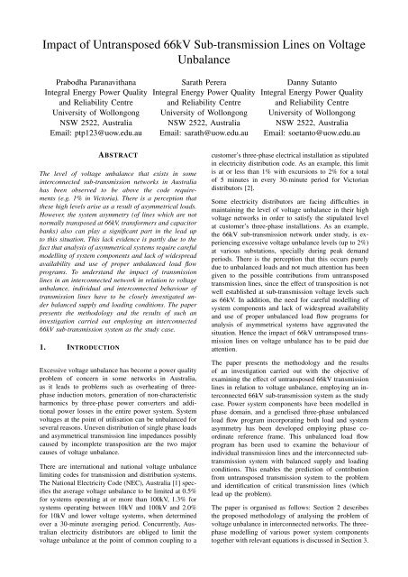
Impact of Untransposed 66kV Sub-transmission Lines on Voltage ...
Impact of Untransposed 66kV Sub-transmission Lines on Voltage ...
Impact of Untransposed 66kV Sub-transmission Lines on Voltage ...

You also want an ePaper? Increase the reach of your titles
YUMPU automatically turns print PDFs into web optimized ePapers that Google loves.
<str<strong>on</strong>g>Impact</str<strong>on</strong>g> <str<strong>on</strong>g>of</str<strong>on</strong>g> <str<strong>on</strong>g>Untransposed</str<strong>on</strong>g> <str<strong>on</strong>g>66kV</str<strong>on</strong>g> <str<strong>on</strong>g>Sub</str<strong>on</strong>g>-<str<strong>on</strong>g>transmissi<strong>on</strong></str<strong>on</strong>g> <str<strong>on</strong>g>Lines</str<strong>on</strong>g> <strong>on</strong> <strong>Voltage</strong><br />
Unbalance<br />
Prabodha Paranavithana<br />
Integral Energy Power Quality<br />
and Reliability Centre<br />
University <str<strong>on</strong>g>of</str<strong>on</strong>g> Woll<strong>on</strong>g<strong>on</strong>g<br />
NSW 2522, Australia<br />
Email: ptp123@uow.edu.au<br />
Sarath Perera<br />
Integral Energy Power Quality<br />
and Reliability Centre<br />
University <str<strong>on</strong>g>of</str<strong>on</strong>g> Woll<strong>on</strong>g<strong>on</strong>g<br />
NSW 2522, Australia<br />
Email: sarath@uow.edu.au<br />
Danny Sutanto<br />
Integral Energy Power Quality<br />
and Reliability Centre<br />
University <str<strong>on</strong>g>of</str<strong>on</strong>g> Woll<strong>on</strong>g<strong>on</strong>g<br />
NSW 2522, Australia<br />
Email: soetanto@uow.edu.au<br />
ABSTRACT<br />
The level <str<strong>on</strong>g>of</str<strong>on</strong>g> voltage unbalance that exists in some<br />
interc<strong>on</strong>nected sub-<str<strong>on</strong>g>transmissi<strong>on</strong></str<strong>on</strong>g> networks in Australia<br />
has been observed to be above the code requirements<br />
(e.g. 1% in Victoria). There is a percepti<strong>on</strong> that<br />
these high levels arise as a result <str<strong>on</strong>g>of</str<strong>on</strong>g> asymmetrical loads.<br />
However, the system asymmetry (<str<strong>on</strong>g>of</str<strong>on</strong>g> lines which are not<br />
normally transposed at <str<strong>on</strong>g>66kV</str<strong>on</strong>g>, transformers and capacitor<br />
banks) also can play a significant part in the lead up<br />
to this situati<strong>on</strong>. This lack evidence is partly due to the<br />
fact that analysis <str<strong>on</strong>g>of</str<strong>on</strong>g> asymmetrical systems require careful<br />
modelling <str<strong>on</strong>g>of</str<strong>on</strong>g> system comp<strong>on</strong>ents and lack <str<strong>on</strong>g>of</str<strong>on</strong>g> widespread<br />
availability and use <str<strong>on</strong>g>of</str<strong>on</strong>g> proper unbalanced load flow<br />
programs. To understand the impact <str<strong>on</strong>g>of</str<strong>on</strong>g> <str<strong>on</strong>g>transmissi<strong>on</strong></str<strong>on</strong>g><br />
lines in an interc<strong>on</strong>nected network in relati<strong>on</strong> to voltage<br />
unbalance, individual and interc<strong>on</strong>nected behaviour <str<strong>on</strong>g>of</str<strong>on</strong>g><br />
<str<strong>on</strong>g>transmissi<strong>on</strong></str<strong>on</strong>g> lines have to be closely investigated under<br />
balanced supply and loading c<strong>on</strong>diti<strong>on</strong>s. The paper<br />
presents the methodology and the results <str<strong>on</strong>g>of</str<strong>on</strong>g> such an<br />
investigati<strong>on</strong> carried out employing an interc<strong>on</strong>nected<br />
<str<strong>on</strong>g>66kV</str<strong>on</strong>g> sub-<str<strong>on</strong>g>transmissi<strong>on</strong></str<strong>on</strong>g> system as the study case.<br />
1. INTRODUCTION<br />
Excessive voltage unbalance has become a power quality<br />
problem <str<strong>on</strong>g>of</str<strong>on</strong>g> c<strong>on</strong>cern in some networks in Australia,<br />
as it leads to problems such as overheating <str<strong>on</strong>g>of</str<strong>on</strong>g> threephase<br />
inducti<strong>on</strong> motors, generati<strong>on</strong> <str<strong>on</strong>g>of</str<strong>on</strong>g> n<strong>on</strong>-characteristic<br />
harm<strong>on</strong>ics by three-phase power c<strong>on</strong>verters and additi<strong>on</strong>al<br />
power losses in the entire power system. System<br />
voltages at the point <str<strong>on</strong>g>of</str<strong>on</strong>g> utilisati<strong>on</strong> can be unbalanced for<br />
several reas<strong>on</strong>s. Uneven distributi<strong>on</strong> <str<strong>on</strong>g>of</str<strong>on</strong>g> single phase loads<br />
and asymmetrical <str<strong>on</strong>g>transmissi<strong>on</strong></str<strong>on</strong>g> line impedances possibly<br />
caused by incomplete transpositi<strong>on</strong> are the two major<br />
causes <str<strong>on</strong>g>of</str<strong>on</strong>g> voltage unbalance.<br />
There are internati<strong>on</strong>al and nati<strong>on</strong>al voltage unbalance<br />
limiting codes for <str<strong>on</strong>g>transmissi<strong>on</strong></str<strong>on</strong>g> and distributi<strong>on</strong> systems.<br />
The Nati<strong>on</strong>al Electricity Code (NEC), Australia [1] specifies<br />
the average voltage unbalance to be limited at 0.5%<br />
for systems operating at or more than 100kV, 1.3% for<br />
systems operating between 10kV and 100kV and 2.0%<br />
for 10kV and lower voltage systems, when determined<br />
over a 30-minute averaging period. C<strong>on</strong>currently, Australian<br />
electricity distributors are obliged to limit the<br />
voltage unbalance at the point <str<strong>on</strong>g>of</str<strong>on</strong>g> comm<strong>on</strong> coupling to a<br />
customer’s three-phase electrical installati<strong>on</strong> as stipulated<br />
in electricity distributi<strong>on</strong> code. As an example, this limit<br />
is at or less than 1% with excursi<strong>on</strong>s to 2% for a total<br />
<str<strong>on</strong>g>of</str<strong>on</strong>g> 5 minutes in every 30-minute period for Victorian<br />
distributors [2].<br />
Some electricity distributors are facing difficulties in<br />
maintaining the level <str<strong>on</strong>g>of</str<strong>on</strong>g> voltage unbalance in their high<br />
voltage networks in order to satisfy the stipulated level<br />
at customer’s three-phase installati<strong>on</strong>s. As an example,<br />
the <str<strong>on</strong>g>66kV</str<strong>on</strong>g> sub-<str<strong>on</strong>g>transmissi<strong>on</strong></str<strong>on</strong>g> network under study, is experiencing<br />
excessive voltage unbalance levels (up to 2%)<br />
at various substati<strong>on</strong>s, specially during peak demand<br />
periods. There is the percepti<strong>on</strong> that this occurs purely<br />
due to unbalanced loads and not much attenti<strong>on</strong> has been<br />
given to the possible c<strong>on</strong>tributi<strong>on</strong>s from untransposed<br />
<str<strong>on</strong>g>transmissi<strong>on</strong></str<strong>on</strong>g> lines, since the effect <str<strong>on</strong>g>of</str<strong>on</strong>g> transpositi<strong>on</strong> is not<br />
well established at sub-<str<strong>on</strong>g>transmissi<strong>on</strong></str<strong>on</strong>g> voltage levels such<br />
as <str<strong>on</strong>g>66kV</str<strong>on</strong>g>. In additi<strong>on</strong>, the need for careful modelling <str<strong>on</strong>g>of</str<strong>on</strong>g><br />
system comp<strong>on</strong>ents and lack <str<strong>on</strong>g>of</str<strong>on</strong>g> widespread availability<br />
and use <str<strong>on</strong>g>of</str<strong>on</strong>g> proper unbalanced load flow programs for<br />
analysis <str<strong>on</strong>g>of</str<strong>on</strong>g> asymmetrical systems have aggravated the<br />
situati<strong>on</strong>. Hence the impact <str<strong>on</strong>g>of</str<strong>on</strong>g> <str<strong>on</strong>g>66kV</str<strong>on</strong>g> untransposed <str<strong>on</strong>g>transmissi<strong>on</strong></str<strong>on</strong>g><br />
lines <strong>on</strong> voltage unbalance has to be paid due<br />
attenti<strong>on</strong>.<br />
The paper presents the methodology and the results<br />
<str<strong>on</strong>g>of</str<strong>on</strong>g> an investigati<strong>on</strong> carried out with the objective <str<strong>on</strong>g>of</str<strong>on</strong>g><br />
examining the effect <str<strong>on</strong>g>of</str<strong>on</strong>g> untransposed <str<strong>on</strong>g>66kV</str<strong>on</strong>g> <str<strong>on</strong>g>transmissi<strong>on</strong></str<strong>on</strong>g><br />
lines in relati<strong>on</strong> to voltage unbalance, employing an interc<strong>on</strong>nected<br />
<str<strong>on</strong>g>66kV</str<strong>on</strong>g> sub-<str<strong>on</strong>g>transmissi<strong>on</strong></str<strong>on</strong>g> system as the study<br />
case. Power system comp<strong>on</strong>ents have been modelled in<br />
phase domain, and a genelised three-phase unbalanced<br />
load flow program incorporating both load and system<br />
asymmetry has been developed employing phase coordinate<br />
reference frame. This unbalanced load flow<br />
program has been used to examine the behaviour <str<strong>on</strong>g>of</str<strong>on</strong>g><br />
individual <str<strong>on</strong>g>transmissi<strong>on</strong></str<strong>on</strong>g> lines and the interc<strong>on</strong>nected sub<str<strong>on</strong>g>transmissi<strong>on</strong></str<strong>on</strong>g><br />
system with balanced supply and loading<br />
c<strong>on</strong>diti<strong>on</strong>s. This enables the predicti<strong>on</strong> <str<strong>on</strong>g>of</str<strong>on</strong>g> c<strong>on</strong>tributi<strong>on</strong><br />
from untransposed <str<strong>on</strong>g>transmissi<strong>on</strong></str<strong>on</strong>g> system to the problem<br />
and identificati<strong>on</strong> <str<strong>on</strong>g>of</str<strong>on</strong>g> critical <str<strong>on</strong>g>transmissi<strong>on</strong></str<strong>on</strong>g> lines (which<br />
lead up the problem).<br />
The paper is organised as follows: Secti<strong>on</strong> 2 describes<br />
the proposed methodology <str<strong>on</strong>g>of</str<strong>on</strong>g> analysing the problem <str<strong>on</strong>g>of</str<strong>on</strong>g><br />
voltage unbalance in interc<strong>on</strong>nected networks. The threephase<br />
modelling <str<strong>on</strong>g>of</str<strong>on</strong>g> various power system comp<strong>on</strong>ents<br />
together with relevant equati<strong>on</strong>s is discussed in Secti<strong>on</strong> 3.
The formulati<strong>on</strong> <str<strong>on</strong>g>of</str<strong>on</strong>g> the generalised three-phase load flow<br />
method is presented in Secti<strong>on</strong> 4. Results obtained from<br />
analysis <str<strong>on</strong>g>of</str<strong>on</strong>g> the study system are given in Secti<strong>on</strong> 5<br />
and Secti<strong>on</strong> 6 summarises the results and gives broad<br />
c<strong>on</strong>clusi<strong>on</strong>s.<br />
2. METHODOLOGY<br />
To analyse the problem <str<strong>on</strong>g>of</str<strong>on</strong>g> voltage unbalance in interc<strong>on</strong>nected<br />
power networks, a three-phase power flow<br />
method incorporating three-phase modelling <str<strong>on</strong>g>of</str<strong>on</strong>g> power<br />
system comp<strong>on</strong>ents is needed.<br />
2.1. SPECIAL REQUIREMENTS<br />
Techniques for three-phase power flow analysis cannot<br />
be developed by simply extending the well established<br />
balanced positive sequence based power flow methods<br />
into three phases. Representati<strong>on</strong> <str<strong>on</strong>g>of</str<strong>on</strong>g> different resp<strong>on</strong>ses<br />
<str<strong>on</strong>g>of</str<strong>on</strong>g> system comp<strong>on</strong>ents (e.g. three-phase inducti<strong>on</strong> motors)<br />
to unbalanced excitati<strong>on</strong>, and formulati<strong>on</strong> <str<strong>on</strong>g>of</str<strong>on</strong>g> threephase<br />
power flow equati<strong>on</strong>s in a generalised way in<br />
order to allow the user to incorporate numerous comp<strong>on</strong>ent<br />
c<strong>on</strong>necti<strong>on</strong>s (e.g. single phase loads), need to<br />
be uniquely addressed in developing a three-phase load<br />
flow method [3]. The method used here takes the above<br />
two requirements into account in modelling <str<strong>on</strong>g>of</str<strong>on</strong>g> system<br />
comp<strong>on</strong>ents and formulating the three-phase load flow<br />
equati<strong>on</strong>s.<br />
2.2. SYMMETRICAL COMPONENTS VERSUS<br />
PHASE CO-ORDINATES<br />
The available literature proposes [4]-[6] two basic approaches<br />
to three-phase load flow analysis based <strong>on</strong><br />
symmetrical comp<strong>on</strong>ents and phase co-ordinates.<br />
Analysis <str<strong>on</strong>g>of</str<strong>on</strong>g> unbalanced power system problems has been<br />
traditi<strong>on</strong>ally based <strong>on</strong> symmetrical comp<strong>on</strong>ent quantities<br />
because <str<strong>on</strong>g>of</str<strong>on</strong>g> the advantages <str<strong>on</strong>g>of</str<strong>on</strong>g> the availability <str<strong>on</strong>g>of</str<strong>on</strong>g> sequence<br />
impedances for power system comp<strong>on</strong>ents and decoupled<br />
nature <str<strong>on</strong>g>of</str<strong>on</strong>g> most <str<strong>on</strong>g>of</str<strong>on</strong>g> power system comp<strong>on</strong>ents in symmetrical<br />
comp<strong>on</strong>ent reference frame [4]. However, the<br />
use <str<strong>on</strong>g>of</str<strong>on</strong>g> phase co-ordinates has been identified as the best<br />
way to represent three-phase power system comp<strong>on</strong>ents<br />
since 1960s [5], as it maintains the initial physical<br />
identity <str<strong>on</strong>g>of</str<strong>on</strong>g> the system with regard to line parameters and<br />
variables such as nodal voltages and line currents. The<br />
<strong>on</strong>ly drawback <str<strong>on</strong>g>of</str<strong>on</strong>g> this approach is that the size <str<strong>on</strong>g>of</str<strong>on</strong>g> the<br />
problem is significantly large compared to which uses<br />
symmetrical comp<strong>on</strong>ents [6]. In this study, three-phase<br />
power flow technique uses phase co-ordinates, disregarding<br />
the computati<strong>on</strong>al advantages associated with the<br />
symmetrical comp<strong>on</strong>ent approach.<br />
3. MODELLING OF SYSTEM COMPO-<br />
NENTS<br />
This secti<strong>on</strong> describes the modelling <str<strong>on</strong>g>of</str<strong>on</strong>g> various comp<strong>on</strong>ents<br />
that exist in the study network.<br />
Generalised modelling <str<strong>on</strong>g>of</str<strong>on</strong>g> power system comp<strong>on</strong>ents<br />
(e.g. model for a synchr<strong>on</strong>ous machine with no predetermined<br />
c<strong>on</strong>necti<strong>on</strong> form) in phase domain is needed<br />
in order to support a generalised three-phase power flow<br />
method. In additi<strong>on</strong>, the different resp<strong>on</strong>ses <str<strong>on</strong>g>of</str<strong>on</strong>g> power system<br />
comp<strong>on</strong>ents to positive, negative and zero sequence<br />
voltage or current are to be c<strong>on</strong>sidered in modelling <str<strong>on</strong>g>of</str<strong>on</strong>g><br />
system comp<strong>on</strong>ents.<br />
3.1. THREE-PHASE SYNCHRONOUS MACHINES<br />
The model used here is based <strong>on</strong> [7] which takes different<br />
machine resp<strong>on</strong>ses for positive, negative and zero<br />
sequence current injecti<strong>on</strong>s into account. It is a positive<br />
sequence voltage source behind the generator admittance<br />
matrix ([Y g ]) with no pre-determined c<strong>on</strong>necti<strong>on</strong> form as<br />
illustrated in Figure 1.<br />
Figure 1: Three-phase generator model<br />
For the system in Figure 1,<br />
[I km ] = [Y g ]([V k ] − [V m ] − [E]) (1)<br />
where,<br />
[V k ] = [V ka V kb V kc ] T , voltages <strong>on</strong> side k<br />
[V m ] = [V ma V mb V mc ] T , voltages <strong>on</strong> side m<br />
[E] = [E p a 2 E p aE p ] T , internal voltages<br />
[I km ] = [I km−a I km−b I km−c ] T , currents from side k<br />
to side m<br />
[Y g ] self = (Y0+2Yn)<br />
3<br />
, generator self admittance<br />
[Y g ] mutual = (Y0−Yn)<br />
3<br />
, generator mutual admittance<br />
a = e j2π<br />
3<br />
subscripts/superscripts:<br />
a, b, c - three phases<br />
p, n, 0 - positive, negative and zero sequence comp<strong>on</strong>ents<br />
respectively<br />
T - transposed matrix<br />
3.2. PASSIVE LOADS<br />
The exp<strong>on</strong>ential load model [8] which takes voltage (V )<br />
dependency <str<strong>on</strong>g>of</str<strong>on</strong>g> active (P ) and reactive (Q) power into<br />
account is used here. This is specified as a single phase<br />
branch between two nodes as shown in Figure 2, allowing<br />
representati<strong>on</strong> <str<strong>on</strong>g>of</str<strong>on</strong>g> different load c<strong>on</strong>figurati<strong>on</strong>s.<br />
Figure 2: Single-phase load model<br />
P = P 0<br />
( V<br />
V 0<br />
) α<br />
(2)<br />
Q = Q 0<br />
( V<br />
V 0<br />
) β<br />
(3)
where,<br />
α - voltage index for active power<br />
β - voltage index for reactive power<br />
subscripts:<br />
0 - referred to rated c<strong>on</strong>diti<strong>on</strong>s<br />
The α and β parameters <str<strong>on</strong>g>of</str<strong>on</strong>g> this model can be set<br />
to represent the aggregate effect <str<strong>on</strong>g>of</str<strong>on</strong>g> different types <str<strong>on</strong>g>of</str<strong>on</strong>g><br />
composite loads (e.g. resistive loads, lighting).<br />
3.3. TRANSMISSION LINES<br />
Overhead <str<strong>on</strong>g>transmissi<strong>on</strong></str<strong>on</strong>g> lines are modelled as electromagnetically<br />
coupled impedance matrices in phase coordinates.<br />
Phase impedance matrix ([Z pq ] (3×3) ) for a<br />
three-phase <str<strong>on</strong>g>transmissi<strong>on</strong></str<strong>on</strong>g> system with earth return is<br />
derived starting from Cars<strong>on</strong>’s formula [9].<br />
( )<br />
De<br />
Z pq = R d +R s +k ln<br />
D pq<br />
( )<br />
De<br />
Z pq = R d + k ln<br />
D pq<br />
Ω/m, when p = q (4)<br />
Ω/m, when p ≠ q (5)<br />
where,<br />
R d = 9.869 × 10 −7 √f<br />
Ω/m, earth resistance<br />
D e = 658.376 ×<br />
ro<br />
f<br />
m<br />
k = 2 × { 10 −7 H/m<br />
c<strong>on</strong>ductor GMR (m), when p = q<br />
D pq −<br />
GMD between p and q (m), when p ≠ q<br />
R s - ac resistance <str<strong>on</strong>g>of</str<strong>on</strong>g> the c<strong>on</strong>ductor (Ω/m)<br />
f - operating frequency (Hz)<br />
r o - earth resistivity (Ωm)<br />
subscripts:<br />
p and q = a, b, c<br />
Since individual lines <str<strong>on</strong>g>of</str<strong>on</strong>g> the study system c<strong>on</strong>sist <str<strong>on</strong>g>of</str<strong>on</strong>g><br />
number <str<strong>on</strong>g>of</str<strong>on</strong>g> secti<strong>on</strong>s with different tower c<strong>on</strong>figurati<strong>on</strong>s<br />
and c<strong>on</strong>ductor material, the phase impedance matrix is<br />
obtained for each secti<strong>on</strong> and the resultant impedance<br />
matrix for the entire line is derived by combining the<br />
secti<strong>on</strong>al impedance matrices.<br />
3.4. CAPACITOR BANKS<br />
Three-phase capacitor banks are c<strong>on</strong>sidered as passive<br />
elements and are modelled as a diag<strong>on</strong>al impedance<br />
matrix. This allows reactive power injecti<strong>on</strong> by capacitor<br />
banks to be determined by the nodal voltage.<br />
4. FORMULATION OF THREE-PHASE<br />
POWER FLOW EQUATIONS<br />
4.1. CONCEPT OF COMPONENT LEVEL POWER<br />
FLOW CONSTRAINTS<br />
A unique problem in three-phase power flow analysis<br />
is the need to model numerous comp<strong>on</strong>ent c<strong>on</strong>necti<strong>on</strong>s,<br />
such as the phase to phase or delta c<strong>on</strong>necti<strong>on</strong>s <str<strong>on</strong>g>of</str<strong>on</strong>g> loads,<br />
and impedance grounded star or delta c<strong>on</strong>necti<strong>on</strong>s <str<strong>on</strong>g>of</str<strong>on</strong>g><br />
generators. The c<strong>on</strong>cepts <str<strong>on</strong>g>of</str<strong>on</strong>g> specifying power flow c<strong>on</strong>straints<br />
for each bus or each phase <str<strong>on</strong>g>of</str<strong>on</strong>g> a bus cannot take<br />
comp<strong>on</strong>ent c<strong>on</strong>necti<strong>on</strong>s into account. It is therefore not<br />
suitable for generalised power flow analysis. In view <str<strong>on</strong>g>of</str<strong>on</strong>g><br />
the fact that the power c<strong>on</strong>straints such as specified generati<strong>on</strong><br />
(or c<strong>on</strong>sumpti<strong>on</strong>) <str<strong>on</strong>g>of</str<strong>on</strong>g> real power are the properties<br />
<str<strong>on</strong>g>of</str<strong>on</strong>g> comp<strong>on</strong>ents instead <str<strong>on</strong>g>of</str<strong>on</strong>g> buses [7]. Therefore the load<br />
flow c<strong>on</strong>straints for each power system comp<strong>on</strong>ent are<br />
expressed in comp<strong>on</strong>ent level here, instead <str<strong>on</strong>g>of</str<strong>on</strong>g> c<strong>on</strong>straints<br />
<strong>on</strong> nodal quantities which have been used in traditi<strong>on</strong>al<br />
power flow methods.<br />
Since each comp<strong>on</strong>ent can be c<strong>on</strong>nected in any form<br />
using node renaming, arbitrary comp<strong>on</strong>ent c<strong>on</strong>necti<strong>on</strong>s<br />
with power flow c<strong>on</strong>straints can be easily represented.<br />
Furthermore, the approach allows the c<strong>on</strong>necti<strong>on</strong> <str<strong>on</strong>g>of</str<strong>on</strong>g><br />
different load types into the same network bus, thus<br />
providing the capability to model a wide variety <str<strong>on</strong>g>of</str<strong>on</strong>g><br />
unbalanced bus loading c<strong>on</strong>diti<strong>on</strong>s.<br />
4.2. COMPONENT CONSTRAINTS<br />
Comp<strong>on</strong>ents with power flow c<strong>on</strong>straints such as loads<br />
and generators are represented by their respective comp<strong>on</strong>ent<br />
models and the associated power flow c<strong>on</strong>straints,<br />
as follows:<br />
(a) Slack generator: The specified c<strong>on</strong>straints are the<br />
magnitude and the phase angle <str<strong>on</strong>g>of</str<strong>on</strong>g> the positive sequence<br />
voltage(V specified ) at the machine terminals.<br />
where,<br />
[T ] = 1 3 [1 a a2 ]<br />
[T ]([V k ] − [V m ]) = V specified (6)<br />
(b) PV generator: The specified c<strong>on</strong>straints are the threephase<br />
active power output (P 3φ, specified ) and the magnitude<br />
<str<strong>on</strong>g>of</str<strong>on</strong>g> the positive sequence voltage (V specified ) at the<br />
machine terminals.<br />
Real ( − [I km ] H ([V k ] − [V m ]) ) = P 3φ, specified (7)<br />
| [T ]([V k ] − [V m ]) |= V specified (8)<br />
where,<br />
superscripts:<br />
H - denotes c<strong>on</strong>jugate transposed<br />
The machine internal voltage (E) in (1) is unknown and<br />
must be adjusted to satisfy the above machine power flow<br />
c<strong>on</strong>straints.<br />
(c) Loads: The specified c<strong>on</strong>straints are the single phase<br />
active and reactive power ((P + jQ) 1φ, specified ) c<strong>on</strong>sumpti<strong>on</strong>.<br />
I H km(V k − V m ) = (P + jQ) 1φ, specified (9)<br />
The network (<str<strong>on</strong>g>transmissi<strong>on</strong></str<strong>on</strong>g> lines and capacitor banks)<br />
which does not have power flow c<strong>on</strong>straints is repre-
sented by their respective impedance/admittance matrices.<br />
4.3. POWER FLOW EQUATIONS<br />
With representati<strong>on</strong> <str<strong>on</strong>g>of</str<strong>on</strong>g> system comp<strong>on</strong>ents as described<br />
in Secti<strong>on</strong> 4.2, the interacti<strong>on</strong>s between the network<br />
and the system comp<strong>on</strong>ents with power flow c<strong>on</strong>straints<br />
(loads and generators) are obtained by the comp<strong>on</strong>ent<br />
branch currents using (10). These branch currents are<br />
unknowns and are to be determined by the load flow.<br />
C to support the network. Most <str<strong>on</strong>g>of</str<strong>on</strong>g> the <str<strong>on</strong>g>transmissi<strong>on</strong></str<strong>on</strong>g> lines<br />
<str<strong>on</strong>g>of</str<strong>on</strong>g> the network are more than 50km l<strong>on</strong>g and are not<br />
systematically transposed. The network is supplying for<br />
low voltage customers, including three-phase customers<br />
such as water boards and irrigators.<br />
[Y ][V ] + [I u ] = 0 (10)<br />
where,<br />
[Y ] - network nodal admittance matrix<br />
[V ] - nodal voltage vector<br />
[I u ] - vector <str<strong>on</strong>g>of</str<strong>on</strong>g> unknown currents (associated with<br />
power flow c<strong>on</strong>straints) leaving each node<br />
Collecting all the related equati<strong>on</strong>s together, the threephase<br />
power flow problem can be formulated as:<br />
Generator model:<br />
f 1 = [I km ] − [Y g ]([V k ] − [V m ] − [E]) = 0 (11)<br />
Generator c<strong>on</strong>straint:<br />
f 2 = G([I km ], [V k ], [V m ]) − K specified = 0 (12)<br />
Load c<strong>on</strong>straint:<br />
f 3 = I H km(V k − V m ) − (P + jQ) 1φ, specified = 0 (13)<br />
Network:<br />
f 4 = [Y ][V ] + [I u ] = 0 (14)<br />
Figure 3: Study network<br />
Despite the fact that the voltage unbalance at A is<br />
negligible, the level <str<strong>on</strong>g>of</str<strong>on</strong>g> voltage unbalance that exists at<br />
down stream load buses (G, H and I) exceeds 2% while<br />
there is a significant level <str<strong>on</strong>g>of</str<strong>on</strong>g> voltage unbalance (1.2%)<br />
at D and F during peak demand periods. Initial studies<br />
have revealed that significant load unbalance existed at<br />
G and H. The voltage unbalance in the network has<br />
reduced significantly after balancing the loads at G and<br />
H, although the subsequent levels are still excessive.<br />
The general form <str<strong>on</strong>g>of</str<strong>on</strong>g> these equati<strong>on</strong>s can be written as:<br />
F ([x]) = 0 (15)<br />
where,<br />
[I u ] = [I generator I load ] T<br />
[x] = [V E p I generator I load ] T<br />
F = [f 1 f 2 f 3 f 4 ] T<br />
[I generator ] - vector <str<strong>on</strong>g>of</str<strong>on</strong>g> generator currents<br />
[I load ] - vector <str<strong>on</strong>g>of</str<strong>on</strong>g> load currents<br />
Equati<strong>on</strong> (15) is a set <str<strong>on</strong>g>of</str<strong>on</strong>g> n<strong>on</strong>linear algebraic equati<strong>on</strong>s,<br />
which is solved employing the well established Newt<strong>on</strong>-<br />
Raphs<strong>on</strong> iterative technique.<br />
5. CASE STUDY<br />
Figure 4: Variati<strong>on</strong> <str<strong>on</strong>g>of</str<strong>on</strong>g> VUF (%) at different nodes<br />
with time<br />
Table 1: VUF at different load substati<strong>on</strong>s during<br />
peak demand periods<br />
<str<strong>on</strong>g>Sub</str<strong>on</strong>g> Predicted VUF (%) Measured<br />
-stati<strong>on</strong> with balanced loads VUF (%)<br />
I 1.3 -<br />
H 1.2 2<br />
G 0.9 1.8<br />
D 0.5 1.2<br />
F 0.4 1<br />
The <str<strong>on</strong>g>66kV</str<strong>on</strong>g> sub-<str<strong>on</strong>g>transmissi<strong>on</strong></str<strong>on</strong>g> system under study as shown<br />
in Figure 3 is energised at A (bulk entry point) where<br />
the voltage unbalance is known to be negligible. In<br />
additi<strong>on</strong>, there are generators c<strong>on</strong>nected at B and C where<br />
the generator at C operates during limited time periods<br />
<strong>on</strong>ly. Further, capacitors are present at each substati<strong>on</strong> to<br />
support the VAR requirement and a SVC is available at<br />
The work is carried out to understand the impact <str<strong>on</strong>g>of</str<strong>on</strong>g><br />
untransposed <str<strong>on</strong>g>66kV</str<strong>on</strong>g> <str<strong>on</strong>g>transmissi<strong>on</strong></str<strong>on</strong>g> lines <strong>on</strong> the problem<br />
in hand. The behavior <str<strong>on</strong>g>of</str<strong>on</strong>g> individual lines and the interc<strong>on</strong>nected<br />
system in relati<strong>on</strong> to voltage unbalance is<br />
analysed under balanced loading c<strong>on</strong>diti<strong>on</strong>s employing<br />
the developed three-phase load flow program as the<br />
analytical tool.
The Figure 4 shows the variati<strong>on</strong> <str<strong>on</strong>g>of</str<strong>on</strong>g> voltage unbalance<br />
factor (VUF) at different substati<strong>on</strong>s over a 24-hour<br />
period using load flow analysis that synthesises the<br />
actual network operati<strong>on</strong>. This was d<strong>on</strong>e by applying<br />
loads (c<strong>on</strong>stant power) that are similar to what exists,<br />
however applied as balanced loads. It is clear that the<br />
asymmetry <str<strong>on</strong>g>of</str<strong>on</strong>g> the network (due to untransposed lines)<br />
itself produces excessive levels <str<strong>on</strong>g>of</str<strong>on</strong>g> voltage unbalance at<br />
G, H and I load buses and c<strong>on</strong>siderable levels at D and<br />
F as shown in Table 1. The VUF levels caused <strong>on</strong>ly by<br />
system asymmetry at G, H and I down stream load buses<br />
are out <str<strong>on</strong>g>of</str<strong>on</strong>g> the the code requirements, and the situati<strong>on</strong><br />
will be aggravated when the load unbalance comes into<br />
account, as depicted by the measured VUF values given<br />
in Table 1.<br />
Figure 5 illustrates the variati<strong>on</strong> <str<strong>on</strong>g>of</str<strong>on</strong>g> VUF (at receiving<br />
end) with respect to line current (as a percentage to<br />
line’s rated current) for individual lines under balanced<br />
supply (<str<strong>on</strong>g>66kV</str<strong>on</strong>g>) and loading (c<strong>on</strong>stant power loads with<br />
0.9 power factor) c<strong>on</strong>diti<strong>on</strong>s. It is evident from Figure 5<br />
that some lines (F-C, H-I, A-F, A-D and E-D) behave<br />
adversely in relati<strong>on</strong> to voltage unbalance when they are<br />
heavily loaded. Am<strong>on</strong>g these F-C, A-F, A-D and E-D are<br />
significantly loaded under operating c<strong>on</strong>diti<strong>on</strong>s and thus<br />
can have a significant impact <strong>on</strong> the problem (Table 2).<br />
Figure 5: Variati<strong>on</strong> <str<strong>on</strong>g>of</str<strong>on</strong>g> VUF (%) with line current (%)<br />
Table 2: Maximum loading level and respective<br />
VUF (at recieving end) for individual lines<br />
Line Maximum loading VUF (%)<br />
level (%)<br />
F-C 26 1<br />
A-F 30.5 0.6<br />
A-D 39 0.5<br />
E-D 56 0.75<br />
6. CONCLUSIONS AND FUTURE DIREC-<br />
TIONS<br />
<str<strong>on</strong>g>of</str<strong>on</strong>g> the code requirements during peak demand periods,<br />
even when the loads are completely balanced. Analysis <str<strong>on</strong>g>of</str<strong>on</strong>g><br />
individual line behaviour enabled identificati<strong>on</strong> <str<strong>on</strong>g>of</str<strong>on</strong>g> critical<br />
<str<strong>on</strong>g>transmissi<strong>on</strong></str<strong>on</strong>g> lines, which make significant c<strong>on</strong>tributi<strong>on</strong><br />
to the problem. Hence, untransposed lines even at lower<br />
<str<strong>on</strong>g>transmissi<strong>on</strong></str<strong>on</strong>g> voltage levels such as <str<strong>on</strong>g>66kV</str<strong>on</strong>g>, are investigated<br />
as a primary cause <str<strong>on</strong>g>of</str<strong>on</strong>g> voltage unbalance.<br />
In relati<strong>on</strong> to unbalanced load flow analysis it is crucial<br />
that advanced load modelling be undertaken. This is<br />
due to that fact that loads such as inducti<strong>on</strong> machines<br />
behave differently when subjected to unbalanced supply<br />
voltages. This is in c<strong>on</strong>trary to the behaviour exhibited<br />
by static loads such as resistive loads.<br />
REFERENCES<br />
[1] System Standards, Nati<strong>on</strong>al Electicity Code<br />
Australia, Versi<strong>on</strong> 1.0 - Amendment 9.0,<br />
S5.1a.7, October 2004.<br />
[2] Electricity Distributi<strong>on</strong> Code, Victoria, January<br />
2002.<br />
[3] W. Xu, H. W. Dommel and J. R. Marti, ‘A<br />
Generalised Three-phase Power Flow Method<br />
for the Initialisati<strong>on</strong> <str<strong>on</strong>g>of</str<strong>on</strong>g> EMTP Simulati<strong>on</strong>s’, Int.<br />
C<strong>on</strong>f. <strong>on</strong> Power System Technology, POWER-<br />
CON ’98, Vol. 2, pp. 875-879, 18-21 Aug. 1998.<br />
[4] Xiao-Ping Zhang and Heng Chen, ‘Sequence-<br />
Decoupled Newt<strong>on</strong>-Raphs<strong>on</strong> Three-phase Load<br />
Flow’, Proc. IEEE Regi<strong>on</strong> 10 C<strong>on</strong>f. <strong>on</strong> Computer,<br />
Communicati<strong>on</strong>, C<strong>on</strong>trol and Power Engineering,<br />
TENCON ’93, Vol. 5, Issue 0,<br />
Part 50000, pp. 394 - 397, 19-21 Oct. 1993.<br />
[5] M. A. Laught<strong>on</strong>, ‘Analysis <str<strong>on</strong>g>of</str<strong>on</strong>g> Unbalanced<br />
Poly-phase Networks by the Method <str<strong>on</strong>g>of</str<strong>on</strong>g> Phase<br />
Co-ordinates’, IEE Proc., Vol. 115, No. 8,<br />
Aug. 1968.<br />
[6] M. Abdel-Akher, K. M. Nor and<br />
A. H. A. Rashid, ‘Improved Three-phase Power<br />
Flow Methods using Sequence Comp<strong>on</strong>ents’,<br />
IEEE Trans. <strong>on</strong> Power Systems, Vol. 20,<br />
Issue 3, pp. 1389 - 1397, Aug. 2005.<br />
[7] W. Xu, J. R. Marti and H. W. Dommel, ‘A<br />
Multiphase Harm<strong>on</strong>ic Load Flow Soluti<strong>on</strong> Technique’,<br />
IEEE Trans. <strong>on</strong> Power Systems, Vol. 6,<br />
Issue 1, pp. 174 - 182, Feb. 1991.<br />
[8] Prabha Kundur, ‘Power System Stability and<br />
C<strong>on</strong>trol’, McGraw-Hill, Inc., pp. 271-274, 1993.<br />
[9] Paul M. Anders<strong>on</strong>, ‘Analysis <str<strong>on</strong>g>of</str<strong>on</strong>g> Faulted Power<br />
Systems’, A John Wiley & S<strong>on</strong>s, Inc., pp. 71-<br />
83, 1995.<br />
Investigati<strong>on</strong>s were carried out to examine the impact <str<strong>on</strong>g>of</str<strong>on</strong>g><br />
<str<strong>on</strong>g>66kV</str<strong>on</strong>g> untransposed <str<strong>on</strong>g>transmissi<strong>on</strong></str<strong>on</strong>g> lines <strong>on</strong> voltage unbalance.<br />
An Interc<strong>on</strong>nected <str<strong>on</strong>g>66kV</str<strong>on</strong>g> sub-<str<strong>on</strong>g>transmissi<strong>on</strong></str<strong>on</strong>g> network<br />
and its individual lines were analysed under balanced<br />
loading c<strong>on</strong>diti<strong>on</strong>s, employing a three-phase power flow<br />
program. It is seen that the level <str<strong>on</strong>g>of</str<strong>on</strong>g> voltage unbalance at<br />
some load substati<strong>on</strong>s <str<strong>on</strong>g>of</str<strong>on</strong>g> the interc<strong>on</strong>nected system is out