Impact of Untransposed 66kV Sub-transmission Lines on Voltage ...
Impact of Untransposed 66kV Sub-transmission Lines on Voltage ...
Impact of Untransposed 66kV Sub-transmission Lines on Voltage ...

Create successful ePaper yourself
Turn your PDF publications into a flip-book with our unique Google optimized e-Paper software.
sented by their respective impedance/admittance matrices.<br />
4.3. POWER FLOW EQUATIONS<br />
With representati<strong>on</strong> <str<strong>on</strong>g>of</str<strong>on</strong>g> system comp<strong>on</strong>ents as described<br />
in Secti<strong>on</strong> 4.2, the interacti<strong>on</strong>s between the network<br />
and the system comp<strong>on</strong>ents with power flow c<strong>on</strong>straints<br />
(loads and generators) are obtained by the comp<strong>on</strong>ent<br />
branch currents using (10). These branch currents are<br />
unknowns and are to be determined by the load flow.<br />
C to support the network. Most <str<strong>on</strong>g>of</str<strong>on</strong>g> the <str<strong>on</strong>g>transmissi<strong>on</strong></str<strong>on</strong>g> lines<br />
<str<strong>on</strong>g>of</str<strong>on</strong>g> the network are more than 50km l<strong>on</strong>g and are not<br />
systematically transposed. The network is supplying for<br />
low voltage customers, including three-phase customers<br />
such as water boards and irrigators.<br />
[Y ][V ] + [I u ] = 0 (10)<br />
where,<br />
[Y ] - network nodal admittance matrix<br />
[V ] - nodal voltage vector<br />
[I u ] - vector <str<strong>on</strong>g>of</str<strong>on</strong>g> unknown currents (associated with<br />
power flow c<strong>on</strong>straints) leaving each node<br />
Collecting all the related equati<strong>on</strong>s together, the threephase<br />
power flow problem can be formulated as:<br />
Generator model:<br />
f 1 = [I km ] − [Y g ]([V k ] − [V m ] − [E]) = 0 (11)<br />
Generator c<strong>on</strong>straint:<br />
f 2 = G([I km ], [V k ], [V m ]) − K specified = 0 (12)<br />
Load c<strong>on</strong>straint:<br />
f 3 = I H km(V k − V m ) − (P + jQ) 1φ, specified = 0 (13)<br />
Network:<br />
f 4 = [Y ][V ] + [I u ] = 0 (14)<br />
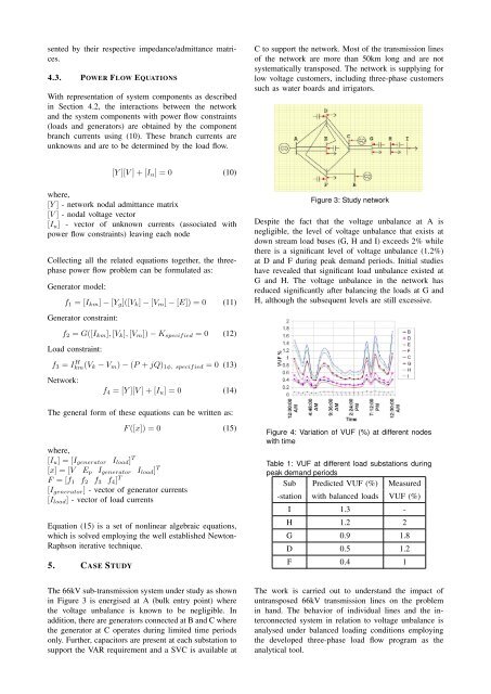
Figure 3: Study network<br />
Despite the fact that the voltage unbalance at A is<br />
negligible, the level <str<strong>on</strong>g>of</str<strong>on</strong>g> voltage unbalance that exists at<br />
down stream load buses (G, H and I) exceeds 2% while<br />
there is a significant level <str<strong>on</strong>g>of</str<strong>on</strong>g> voltage unbalance (1.2%)<br />
at D and F during peak demand periods. Initial studies<br />
have revealed that significant load unbalance existed at<br />
G and H. The voltage unbalance in the network has<br />
reduced significantly after balancing the loads at G and<br />
H, although the subsequent levels are still excessive.<br />
The general form <str<strong>on</strong>g>of</str<strong>on</strong>g> these equati<strong>on</strong>s can be written as:<br />
F ([x]) = 0 (15)<br />
where,<br />
[I u ] = [I generator I load ] T<br />
[x] = [V E p I generator I load ] T<br />
F = [f 1 f 2 f 3 f 4 ] T<br />
[I generator ] - vector <str<strong>on</strong>g>of</str<strong>on</strong>g> generator currents<br />
[I load ] - vector <str<strong>on</strong>g>of</str<strong>on</strong>g> load currents<br />
Equati<strong>on</strong> (15) is a set <str<strong>on</strong>g>of</str<strong>on</strong>g> n<strong>on</strong>linear algebraic equati<strong>on</strong>s,<br />
which is solved employing the well established Newt<strong>on</strong>-<br />
Raphs<strong>on</strong> iterative technique.<br />
5. CASE STUDY<br />
Figure 4: Variati<strong>on</strong> <str<strong>on</strong>g>of</str<strong>on</strong>g> VUF (%) at different nodes<br />
with time<br />
Table 1: VUF at different load substati<strong>on</strong>s during<br />
peak demand periods<br />
<str<strong>on</strong>g>Sub</str<strong>on</strong>g> Predicted VUF (%) Measured<br />
-stati<strong>on</strong> with balanced loads VUF (%)<br />
I 1.3 -<br />
H 1.2 2<br />
G 0.9 1.8<br />
D 0.5 1.2<br />
F 0.4 1<br />
The <str<strong>on</strong>g>66kV</str<strong>on</strong>g> sub-<str<strong>on</strong>g>transmissi<strong>on</strong></str<strong>on</strong>g> system under study as shown<br />
in Figure 3 is energised at A (bulk entry point) where<br />
the voltage unbalance is known to be negligible. In<br />
additi<strong>on</strong>, there are generators c<strong>on</strong>nected at B and C where<br />
the generator at C operates during limited time periods<br />
<strong>on</strong>ly. Further, capacitors are present at each substati<strong>on</strong> to<br />
support the VAR requirement and a SVC is available at<br />
The work is carried out to understand the impact <str<strong>on</strong>g>of</str<strong>on</strong>g><br />
untransposed <str<strong>on</strong>g>66kV</str<strong>on</strong>g> <str<strong>on</strong>g>transmissi<strong>on</strong></str<strong>on</strong>g> lines <strong>on</strong> the problem<br />
in hand. The behavior <str<strong>on</strong>g>of</str<strong>on</strong>g> individual lines and the interc<strong>on</strong>nected<br />
system in relati<strong>on</strong> to voltage unbalance is<br />
analysed under balanced loading c<strong>on</strong>diti<strong>on</strong>s employing<br />
the developed three-phase load flow program as the<br />
analytical tool.