Mathcad - LAPD condenser heat transfer area. rev ... - LArTPC DocDB
Mathcad - LAPD condenser heat transfer area. rev ... - LArTPC DocDB
Mathcad - LAPD condenser heat transfer area. rev ... - LArTPC DocDB

Create successful ePaper yourself
Turn your PDF publications into a flip-book with our unique Google optimized e-Paper software.
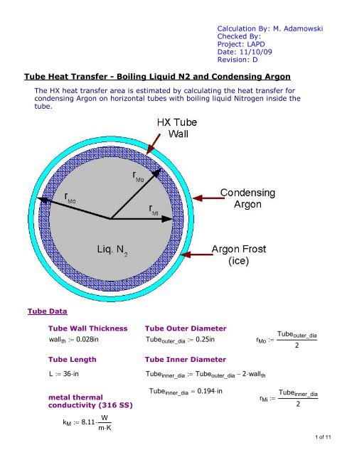
Calculation By: M. Adamowski<br />
Checked By:<br />
Project: <strong>LAPD</strong><br />
Date: 11/10/09<br />
Revision: D<br />
Tube Heat Transfer - Boiling Liquid N2 and Condensing Argon<br />
The HX <strong>heat</strong> <strong>transfer</strong> <strong>area</strong> is estimated by calculating the <strong>heat</strong> <strong>transfer</strong> for<br />
condensing Argon on horizontal tubes with boiling liquid Nitrogen inside the<br />
tube.<br />
Tube Data<br />
Tube Wall Thickness Tube Outer Diameter<br />
Tube outer_dia<br />
wall th 0.028in<br />
Tube outer_dia 0.25in<br />
r Mo <br />
2<br />
Tube Length<br />
Tube Inner Diameter<br />
L 36in<br />
Tube inner_dia Tube outer_dia 2wall th<br />
metal thermal<br />
conductivity (316 SS)<br />
Tube inner_dia<br />
<br />
0.194in<br />
r Mi<br />
<br />
Tube inner_dia<br />
2<br />
k M 8.11<br />
W<br />
mK<br />
1 of 11
Argon Data<br />
Argon physical properties from NIST REPROP<br />
argon liquid density argon vapor density argon liquid visc<br />
ρ Ar_l 1396<br />
kg<br />
ρ Ar_v 0.4<br />
lb<br />
µ Ar_l .261cP<br />
m 3<br />
ft 3<br />
argon liq thermal conductivity<br />
argon ice thermal conductivity<br />
k Ar.liq<br />
128.5<br />
mW<br />
k ice 133<br />
mW<br />
mK<br />
mK<br />
argon condensing<br />
argon <strong>heat</strong> of vaporization<br />
temperature<br />
T Ar 87.8K<br />
h Ar_fg 161<br />
kJ h Ar_fg 69.21754<br />
BTU<br />
kg<br />
lbm<br />
argon freezing temperature<br />
T Ar_freeze<br />
83.8K<br />
T ice T Ar_freeze<br />
2 of 11
Nitrogen Data<br />
Nitrogen physical properties from NIST REPROP<br />
Nitrogen boiling temperature<br />
Nitrogen liquid thermal cond.<br />
T N2<br />
77.3K<br />
k N2_liq 144<br />
mW<br />
mK<br />
Nitrogen liquid density<br />
Nitrogen Heat of<br />
Vaporization<br />
ρ N2_liq 807<br />
kg<br />
Hvap N2 199<br />
kJ<br />
m 3<br />
kg<br />
Nitrogen Vapor<br />
Density<br />
ρ N2_gas 4.5<br />
kg<br />
m 3<br />
Nitrogen Liquid<br />
Viscosity<br />
µ N2_l .162cP<br />
Nitrogen Liquid specific<br />
<strong>heat</strong><br />
Cp N2_l 0.77<br />
kJ<br />
kgK<br />
Mass flow of N2 based on<br />
70% outlet vapor quality<br />
Massflow N2 <br />
240<br />
lb hr<br />
3 of 11
Heat Load<br />
The <strong>heat</strong> load on the HX is taken as twice the <strong>heat</strong> absorbed by the <strong>LAPD</strong> tank<br />
from the environment. Using twice the tank <strong>heat</strong> provides a design margin.<br />
Tank <strong>heat</strong><br />
2106W<br />
Q req 2Tank <strong>heat</strong><br />
Q req 4212W<br />
Boiling Nitrogen Heat Transfer Coefficient<br />
Excess Nitrogen is used to keep the tube side wetted. Under these conditions<br />
the Nitrogen boiling <strong>heat</strong> <strong>transfer</strong> coefficient will be uniform for the whole<br />
tube length.<br />
h N2_boil 1500<br />
kW<br />
m 2 K<br />
this N2 boiling <strong>heat</strong> <strong>transfer</strong> coefficient is<br />
at a a minimum N2 mass flux.<br />
N2 massflux_for_h 70<br />
kg<br />
m 2 s<br />
ref: "Flow boiling <strong>heat</strong> <strong>transfer</strong> characteristics of<br />
nitrogen in plain and wire coil inserted tubes", International Journal of<br />
Heat and Mass Transfer 50 (2007)<br />
4 of 11
Tube <strong>heat</strong> <strong>transfer</strong><br />
The tube <strong>heat</strong> <strong>transfer</strong> is calculated as concentric rings of <strong>heat</strong> <strong>transfer</strong>. The<br />
rings are inner tube metal surface, tube metal wall, Argon ice layer and outer<br />
ice surface. The calculations are arranged starting inside the tube at liquid N2<br />
temperature and then proceeds through the concentric rings to the tube<br />
outside at condensing Argon temperature.<br />
To start the calculation, initial guesses are made for the tube inside metal<br />
temperature and the <strong>heat</strong> flux, q.<br />
Initial Guesses<br />
h Mi<br />
q 200W<br />
h N2_boil<br />
The <strong>heat</strong> <strong>transfer</strong> calculations are define with a <strong>Mathcad</strong> GIVEN block to allow<br />
use of <strong>Mathcad</strong>'s equation solving ability.<br />
Given<br />
q<br />
T Mi T N2 <br />
2π<br />
L<br />
r Mi<br />
h Mi<br />
inner surface formula arranged to solve<br />
for inside tube metal temperature<br />
T Mo T Mi q<br />
<br />
<br />
<br />
<br />
ln r Mo<br />
2π<br />
r Mi<br />
k M<br />
<br />
<br />
<br />
L<br />
<br />
metal tube wall formula arranged to solve<br />
for outside tube metal temperature<br />
<br />
<br />
r ice r Mo exp T Mo T ice<br />
2π<br />
q<br />
k ice<br />
L<br />
<br />
<br />
<br />
Argon ice layer formula arranged to<br />
solve for the radius of the outside<br />
ice surface.<br />
wall ice r ice r Mo<br />
Given block continues on next page >>><br />
5 of 11
Given block continues from p<strong>rev</strong>ious page<br />
The ice outside <strong>heat</strong> <strong>transfer</strong> coefficent is for condensing Argon. This<br />
coefficient is estimated as condenstion on a horizontal tube.<br />
h Ar_condi<br />
<br />
<br />
<br />
<br />
<br />
0.728 g ρ 3<br />
Ar_l ρ Ar_l ρ Ar_v k Ar.liq <br />
<br />
Tube outer_dia µ Ar_l T ice T Ar<br />
<br />
h Ar_fg<br />
<br />
<br />
<br />
1<br />
4<br />
h Ar_cond<br />
<br />
Reh Ar_condi <br />
use the real portion of the 4th root solution<br />
ref: Heat, Mass and Momentum Transfer, by Rohsenow, 1961,<br />
pg 248, Condensation on horizontal tube formula.<br />
q <br />
2π<br />
r ice<br />
<br />
Lh Ar_cond T ice T Ar<br />
outer ice layer <strong>heat</strong> <strong>transfer</strong> formula<br />
arranged to solve for <strong>heat</strong><br />
<strong>transfer</strong>red.<br />
Find the solution to the given equations<br />
Find( q)<br />
q 214.57319W<br />
wall ice 0.06621mm<br />
q<br />
<strong>heat</strong>flux Mi 2π<br />
r Mo L<br />
<strong>heat</strong>flux Mi 11.76293 kW<br />
<br />
<br />
m 2<br />
h Ar_cond 2880.66079<br />
W<br />
m 2 K<br />
6 of 11
Summary of results for require Q of: Q req 4212W<br />
T N2<br />
<br />
77.3 K<br />
wall ice<br />
<br />
0.06621mm<br />
T Mi 77.30942K<br />
T Mo 78.39797K<br />
T ice<br />
<br />
83.8 K<br />
T Ar<br />
<br />
87.8 K<br />
Estimate the Total HX <strong>area</strong> based on outside tube diameter:<br />
HX <strong>area</strong>_o<br />
HX tube_count<br />
Q req<br />
2π<br />
r Mo L<br />
HX <strong>area</strong>_o 3.85428ft 2<br />
q<br />
HX <strong>area</strong>_o<br />
HX tube_count 19.62967<br />
2π<br />
L<br />
r Mo<br />
N2 Mass flux<br />
Massflux N2 <br />
Massflow N2<br />
2<br />
HX tube_count π<br />
r Mi<br />
The N2 massflux for the number of<br />
tubes needed should be equal or<br />
higher than the N2 massflux for the<br />
N2 boiling <strong>heat</strong> <strong>transfer</strong> coefficient.<br />
<br />
Ans if Massflux N2 N2 massflux_for_h<br />
"solution is good"<br />
"massflux low for N2 h data"<br />
<br />
Ans<br />
"solution is good"<br />
Massflux N2 80.77943<br />
kg<br />
m 2 s<br />
7 of 11
Calc <strong>heat</strong> flux for tube inside surface<br />
Heatflux i <br />
2π<br />
Q req<br />
r Mi<br />
L<br />
Q req<br />
q<br />
Heatflux i 15158.41968<br />
W m 2<br />
Calc of overall U<br />
U all<br />
Q req<br />
W<br />
U all 1120.2794<br />
T N2 T Ar HX <strong>area</strong>_o<br />
m 2 U all 197.29261 <br />
K<br />
BTU<br />
hrft 2<br />
R<br />
Calc of tube inlet velocity<br />
V tube_inlet<br />
Massflux N2<br />
V tube_inlet 0.32841<br />
ft<br />
s<br />
ρ N2_liq<br />
8 of 11
N2 Horizontal Tube boiling <strong>heat</strong> <strong>transfer</strong> estimate<br />
Shah Correlation with adjustment for horizontal plain tubes<br />
ref: Engineering Databook III by Wolverine Tube, Inc.<br />
Vapor quality to use in calc<br />
x 0.1<br />
Liquid Froude number<br />
2<br />
Massflux N2<br />
Fr L Fr L 0.20728<br />
2<br />
ρ N2_liq g<br />
Tubeinner_dia<br />
IF Fr.L is greater than 0.04 then the following calc applies<br />
calc Shah's C.o factor<br />
<br />
<br />
1 x<br />
C o <br />
x<br />
<br />
<br />
<br />
0.8<br />
<br />
<br />
<br />
<br />
ρ N2_gas<br />
ρ N2_liq<br />
<br />
<br />
<br />
0.5<br />
C o 0.43308<br />
set Shah's N parameter equal to C.o for this method<br />
N<br />
<br />
C o<br />
9 of 11
calc liquid Reynolds number<br />
<br />
<br />
Massflux N2 1 x Tube inner_dia<br />
Re L Re L 2211.3819<br />
µ N2_l<br />
calc liquid Prandtl number<br />
Cp N2_l µ N2_l<br />
Pr L Pr L 0.86625<br />
k N2_liq<br />
calc liquid phase convective <strong>heat</strong> <strong>transfer</strong> coefficient<br />
by Dittus-Boelter correlation<br />
k N2_liq<br />
0.8 0.4<br />
α L 0.023Re L Pr L <br />
α L 300.776<br />
Tube inner_dia<br />
W<br />
m 2 K<br />
calc convective boiling <strong>heat</strong> <strong>transfer</strong> coefficient from the<br />
liquid phase convective <strong>heat</strong> <strong>transfer</strong> coefficient<br />
α cb<br />
1.8α L<br />
α cb 277.18293<br />
N 0.8<br />
W<br />
m 2 K<br />
10 of 11
calc the boiling number which characterizes nucleate boiling<br />
B o<br />
<br />
Heatflux i<br />
Massflux N2 Hvap N2<br />
B o 0.00094<br />
set appropriate value for Shah's F.s constant<br />
F s 15.43<br />
F.s equals 14.7 when B.o is greater than 0.0011<br />
F.s equals 15.43 when B.o is less than 0.0011<br />
calc the nucleate boiling <strong>heat</strong> <strong>transfer</strong> coefficient<br />
α nb<br />
<br />
0.5<br />
α L F s B o exp 2.74N<br />
0.15<br />
<br />
<br />
α nb 401.84662<br />
W<br />
m 2 K<br />
the two phase flow boiling <strong>heat</strong> <strong>transfer</strong> coefficient is taken<br />
as the larger valve of conventive boiling or nucleate boiling<br />
α tp<br />
<br />
<br />
max α cb α nb<br />
α tp 401.84662<br />
W<br />
m 2 K<br />
The Steiner and Taborek (1992) database has the nucleate boiling <strong>heat</strong> <strong>transfer</strong><br />
coefficient for Nitrogen as 4380 W/m2-K.<br />
The literature value used, 1500 W/m2-K for Nitrogen boiling falls within between<br />
the conservative estimate and the database value of Steiner and Taborek. The<br />
values uses is not too conservative and not too aggressive.<br />
ref: Engineering Data Book III, Wolverine Tube, Inc.<br />
11 of 11