68HC11 Timing System
68HC11 Timing System
68HC11 Timing System

Create successful ePaper yourself
Turn your PDF publications into a flip-book with our unique Google optimized e-Paper software.
<strong>68HC11</strong> <strong>Timing</strong> <strong>System</strong><br />
ELET 3144 R. Alba-Flores 1
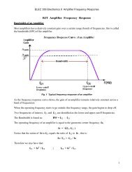
Programmable Timer<br />
• The internal programmable timer is a device that is very<br />
powerful because it allows measuring of time periods,<br />
frequency, delays, etc., in very efficient and easy ways.<br />
• Time periods are measured using different internal timing<br />
devices which includes counters, scalars, flags and<br />
interrupts. This makes the measurement process more<br />
precise and easy to implement .<br />
ELET 3144 R. Alba-Flores 2
Time Measuring Methods<br />
There are different devices that can be used to<br />
measure time include the following:<br />
• – Free running counter<br />
• – Timer overflow flag<br />
• – Timer overflow Interrupt<br />
• – Real time interrupt<br />
• – Output Compare Channels<br />
• – Input Capture Channels<br />
• – Pulse Accumulators
<strong>68HC11</strong> <strong>Timing</strong> <strong>System</strong><br />
The <strong>68HC11</strong> timing is controlled by a crystal oscillator<br />
connected to the XTAL and EXTAL pins on the <strong>68HC11</strong>.<br />
The E clock, which determines the time of each<br />
instruction cycle is ¼ of the crystal frequency.<br />
For the Adapt 11 evaluation board the basic clock is<br />
8MHz and the E clock is 2 MHz.<br />
Therefore the time of each instruction cycle is 0.5 µsec.<br />
ELET 3144 R. Alba-Flores 4
The Free-Running Counter<br />
• The output of the E clock is connected to a 16-bit<br />
counter, called the TCNT register, that is at locations<br />
$100E and $100F.<br />
• TCNT is cleared at RESET.<br />
• This is a read only register. It can not be written but it<br />
will be incremented by every tick of the E clock<br />
ELET 3144 R. Alba-Flores 5
The Free-Running Counter<br />
ELET 3144 R. Alba-Flores 6
The Prescalar<br />
• Resolution is the smallest time interval that can be<br />
measured in a system.<br />
• In the <strong>68HC11</strong> the TCNT register is incremented once<br />
every 0.5 µsec. This 0.5 µsec is the resolution of the<br />
microcontroller system.<br />
• Because the TCNT register is 16 bits, it takes 65,536<br />
( 2 16 ) counts to cycle it around once.<br />
• At the standard clock frequency of 2 MHz, the TCNT<br />
register requires 32.77 msec to roll over ( 65,536 x 0.5<br />
µsec).<br />
ELET 3144 R. Alba-Flores 7
The Prescalar<br />
The <strong>68HC11</strong> contains a prescalar that allows the user to lengthen the<br />
time of each count by dividing the E clock before it is applied to the<br />
input of the TCNT register. The available factor are: 1, 4, 8, and 16 and<br />
can be selected using the bits 0 and bit 1 in the TMSK ($1024) control<br />
register.<br />
PR1 PR0 Prescale<br />
Factor<br />
Bus Frequency (E Clock) 2 MHz<br />
Resolution / Overflow<br />
0 0 1 0.5 µsec / 32.77msec<br />
0 1 4 2 µsec / 131.1 msec<br />
1 0 8 4 µsec / 262.1 msec<br />
1 1 16 8 µsec / 524.3 msec
Timer Overflow<br />
Every time the TCNT register rolls over from<br />
FFFF to 0000, the TOF (Timer Over Flow) bit is set.<br />
The user has no control over TCNT, so TOF will be set<br />
every 32.77 msec<br />
ELET 3144 R. Alba-Flores 9
Clearing the TOF bit<br />
Many of the flag bits in the <strong>68HC11</strong> control registers, including the<br />
TOF, are cleared by writing a 1 into the bit position of the flag.<br />
Writing a 0 into the bit position has no effect on the flag.<br />
A routine to clear TOF is:<br />
SUB1: LDAA #$80 ; Set bit 7 to 1<br />
STAA $1025 ; Write it to TFLG2<br />
RTS<br />
; Return<br />
A flag can also be cleared using a BCLR instruction, with a 0 in<br />
the bit position to be cleared. This is because the <strong>68HC11</strong> uses<br />
the inverse mask to clear the bit. To clear TOF, for example, the<br />
following instructions would work:<br />
LDX #$1000<br />
BCLR $25 , X $7F<br />
10
Example 1<br />
• The TCNT register can be used to create time delays.<br />
A subroutine to cause a time delay for any amount of time is shown<br />
below.<br />
• In this subroutine N1 is the number of 32.77ms intervals that the<br />
time delay requires<br />
• DIFF is the difference between the time of the intervals and the<br />
time of the delay.<br />
• In the subroutine the number of intervals is loaded into register Y .<br />
• The content of TCNT is added to DIFF and stored in register D.<br />
• Note that if the sum is too large for D, then Y must be<br />
incremented by one.<br />
ELET 3144 R. Alba-Flores 11
ORG $2000 ; * This is a General Subroutine for any time delay<br />
N1: FDB ? ? ; Number of 32.77ms intervals<br />
DIFF: FDB ? ? ; Difference between the time of the interval and the time of the delay<br />
TCNT: EQU $100E<br />
TFLG2: EQU $1025<br />
; * Starting of the subroutine<br />
SUB1: LDY N1 ; Y will hold the number of intervals<br />
JSR SUB2 ; Clear TOF<br />
LDD TCNT ; Read TCNT and add the Difference,<br />
ADDD DIFF ; Store the result in D<br />
BCC LOOP1 ; If the sum of TCNT and DIFF is too large for register D<br />
INY<br />
; (i.e. Carry =1 in CCR), then Y must be incremented by one<br />
LOOP1: CPY #0<br />
BEQ LOOP2 ; Go to LOOP2 when done with number of intervals<br />
LOOP3: TST TFLG2 ; Test TOF and wait to be set.<br />
BPL LOOP3 ; When TOF is set clear it and decrement Y<br />
JSR SUB2 ; Go to clear TOF<br />
DEY<br />
BNE LOOP1<br />
LOOP2: CPD TCNT ; Wait until TCNT reaches the content<br />
BHI LOOP2 ; of register D<br />
RTS<br />
; end of GENDEL subroutine, return to main program
; * Subroutine to clear TOF<br />
SUB2: LDAA #$80<br />
STAA TFLG2<br />
RTS<br />
Example 2.<br />
Using the program in example 1, generate a 100-ms time delay.<br />
To create a 100-ms delay, we first divide 100 ms by 32.77 ms, the<br />
timer for TCNT to count around. This gives three cycles (3 X 32.77<br />
ms = 98.31 ms) plus 1.69 ms, or 3380 counts of the E clock.<br />
If N1 is set to 3 and DIFF is set to $0D34 (the hex equivalent of<br />
3380), the program will generate a 100-ms time delay.<br />
Exercise. Write a program to set PB0 high for 100 ms and then<br />
low for 100ms. Use the GENDEL subroutine of example 1.
Input Capture Registers<br />
ELET 3144 R. Alba-Flores 14
Input Capture Registers<br />
Input capture registers are a set of three 16-bit registers<br />
that are connected to the free running counter TCNT<br />
and are controlled by hardware signals (internally or<br />
externally generated)<br />
ELET 3144 R. Alba-Flores 15
Input Capture Registers<br />
• The Input Capture registers can be used to trap or<br />
store the value of the TCNT counter.<br />
• There are 3 Input Capture Registers in the <strong>68HC11</strong>,<br />
TIC1, TIC2 and TIC3, and they are 16 bit registers. They<br />
are connected to pins PA2, PA1 and PA0 (Input only<br />
pins) at Port A.<br />
• These registers make a capture when an edge occurs<br />
in one of these input pins.<br />
• When a capture is made in one of the registers, the time<br />
of the capture (input capture) is copied from the TCNT<br />
register into the Input Capture Register (TIC).<br />
ELET 3144 R. Alba-Flores 16
The three 16-bit TIC registers (TIC1, TIC2, TIC3),<br />
are located at memory locations $1010 to $1015<br />
ELET 3144 R. Alba-Flores 17
The Input Captures are controlled by the edge bits in<br />
TCTL2 ($1021) in the following way:<br />
TCTL2 at $1021<br />
0 0 EDG1B EDG1A EDG2B EDG2A EDG3B EDG3A<br />
EDGxB EDGxA Configuration<br />
0 0 Capture disabled<br />
0 1 Capture on rising edges only<br />
1 0 Capture on falling edge only<br />
1 1 Capture on any edge (rising or falling)<br />
ELET 3144 R. Alba-Flores 18
Example 3.<br />
The time of a falling edge on pin PA1 must be detected.<br />
How must TCTL2 be set up to do this?<br />
Sol.<br />
PA1 is connected to TIC2 (Input Capture Register 2).<br />
The previous table shows that the edge bits must be 1<br />
and 0, respectively, to capture a falling edge, thus the<br />
code:<br />
LDAA #$08<br />
STAA $1021<br />
will set up TCTL2 to capture the time of a falling<br />
edge on PA1.<br />
ELET 3144 R. Alba-Flores 19
Input Flags and Interrupts.<br />
Bits 0, 1 and 2 of the TFLG1 register, at $1023, are used to signal<br />
an input capture on registers 3, 2,and 1, respectively, as shown in<br />
the following figure,<br />
TMSK1 at $1022<br />
OC1I OC2I OC3I OC4I OC5I IC1I IC2I IC3I<br />
TFLG1 at $1023<br />
OC1F OC2F OC3F OC4F OC5F IC1F IC2F IC3F<br />
If a capture is made, the flag will set. The flag can be cleared by<br />
writing a "1" into its bit position.<br />
ELET 3144 R. Alba-Flores 20
The corresponding interrupt bit is in TMSK1. If this bit is set, a capture<br />
will cause an interrupt in accordance with the following table:<br />
Register Pin Location INTERRUPT VECTOR PSEUDO-VECTOR<br />
TIC1 PA2 $FFEE - $FFEF $00E8-$00EA<br />
TIC2 PA1 $FFEC - $FFED $00E5-$00E7<br />
TIC3 PA0 $FFEA - $FFEB $00E2-$00E4<br />
ELET 3144 R. Alba-Flores 21
Example 4.<br />
Determining the Period of a Square Wave.<br />
• The following program determines the period of a square wave<br />
by finding the time between rising edges.<br />
• The TCTL at $1021 is set up to detect rising edges on PA0.<br />
• Then the program jumps to SUB2, which clears the input capture<br />
flag IC3F, and waits until it is set again.<br />
• The time of its setting is stored in TIC3, at $1014 and $1015. This<br />
time is saved in memory (at location FIRST) and SUB2 is executed<br />
again to get the time of the next positive edge.<br />
• The difference between the times is a measure of pulse width.
; *** This is a program to determine the period of a square wave connected to PA0<br />
; *** PA0 is connected to TIC3<br />
TCTL: EQU $21<br />
TFLG1: EQU $23<br />
TIC3: EQU $14<br />
ORG $C100<br />
FIRST: FDB<br />
RESULT: FDB<br />
BEGIN: LDX #$1000<br />
LDS #$C400<br />
LDAA #$01 ; Set the edge bits for IC3<br />
STAA TCTL,X ; to capture on rising edges<br />
JSR SUB2 ; Clear IC3F and wait until it sets<br />
LDD TIC3,X ; Save time of first edge<br />
STD FIRST<br />
JSR SUB2 ; Clear IC3F and wait until it sets<br />
LDD TIC3,X ; Get time of next edge<br />
SUBD FIRST ; Subtract to get the time difference<br />
STD RESULT<br />
SWI<br />
; End of main program<br />
23
; * Subroutine to clear the input capture flag IC3F, and then wait until it sets again<br />
SUB2: LDAA #$01 ; Clear the ICF3<br />
LOOP:<br />
STAA<br />
BRCL<br />
R<br />
RTS<br />
END<br />
TFLG1,X<br />
TFLG1,X $01<br />
LOOP<br />
; Wait until it sets<br />
ELET 3144 R. Alba-Flores 24