Series 3000 - Paso Sound Products
Series 3000 - Paso Sound Products
Series 3000 - Paso Sound Products

Create successful ePaper yourself
Turn your PDF publications into a flip-book with our unique Google optimized e-Paper software.
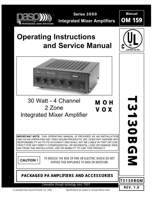
<strong>Series</strong> <strong>3000</strong><br />
Integrated Mixer Amplifiers<br />
Manual<br />
OM 159<br />
Operating Instructions<br />
and Service Manual<br />
30 Watt - 4 Channel<br />
2 Zone<br />
Integrated Mixer Amplifier<br />
CAUTION !<br />
MOH<br />
VOX<br />
IMPORTANT NOTE: THIS OPERATING MANUAL IS PROVIDED AS AN INSTALLATION<br />
AND AS AN OPERATING AID. PASO SOUND PRODUCTS, INC. DOES NOT ASSUME ANY<br />
RESPONSIBILITY AS TO ITS ACCURACY AND SHALL NOT BE LIABLE IN TORT OR CON-<br />
TRACT FOR ANY DIRECT CONSEQUENTIAL OR INCIDENTAL LOSS OR DAMAGE ARIS-<br />
ING FROM THE INSTALLATION, USE OR INABILITY TO USE THIS PRODUCT.<br />
TO REDUCE THE RISK OF FIRE OR ELECTRIC SHOCK DO NOT<br />
EXPOSE THIS APPLIANCE TO RAIN OR MOISTURE<br />
T3130BGM<br />
PACKAGED PA AMPLIFIERS AND ACCESSORIES<br />
Innovation through technology since 1931<br />
© copyright <strong>Paso</strong> <strong>Sound</strong> <strong>Products</strong>, Inc. 1999 Specifications are subject to change without notice<br />
T3130BGM<br />
REV. 1.0
SERIES <strong>3000</strong><br />
DESCRIPTION AND APPLICATIONS<br />
q 4 Channel Inputs - 2 Zone Outputs<br />
q Wide Frequency Response<br />
Very Low Distortion<br />
q Balanced Microphone Input<br />
q Phantom Power on MIC Input with Selector<br />
q Transformer Balanced Telephone Paging Input<br />
q Telephone Input Level Control<br />
q Auxiliary Input With Stereo Summing<br />
q Auxiliary Input Attenuator<br />
q Balanced Program Input<br />
q Independent Input Controls<br />
Bass and Treble Controls<br />
q VOX - Voice Activated Muting<br />
q Direct Muting or Unmuting<br />
q 600 ohm and 8 ohm 1 Watt<br />
Music on Hold Amplifier<br />
q MOH Amplifier Source Selector<br />
q Zone 2, 1 Watt - 8 ohm Output<br />
with Separate Control<br />
q AC Accessory Outlet<br />
q 8 ohm, 25 Volt & 70 Volt<br />
Output Impedance<br />
q Rack Mounting<br />
with Optional Kit<br />
UNPACKING<br />
Immediately upon receipt of the amplifier, inspect the unit<br />
and shipping container for indications of improper handling<br />
or in transit damage. The equipment was carefully inspected<br />
and tested before leaving the factory. Notify the<br />
Transportation Company immediately if any damage is<br />
found. ONLY THE CONSIGNEE CAN FILE A CLAIM WITH<br />
THE CARRIER FOR DAMAGE DURING SHIPMENT. Be<br />
sure to save the carton and packing material as evidence of<br />
damage for the shipper inspection. DO NOT SHIP the unit<br />
back to the factory unless authorized by the factory.<br />
Power Output:<br />
Distortion:<br />
Frequency Response:<br />
Inputs:<br />
Input 1<br />
Input 2<br />
Input 3<br />
Input 4<br />
Sensitivity & Z:<br />
Input 1<br />
Input 2<br />
Input 3<br />
Input 4<br />
Hum & Noise:<br />
Telephone Input:<br />
Music on Hold Output:<br />
Zone 2 Output:<br />
Output Impedance:<br />
Controls:<br />
Front Panel:<br />
Rear Panel<br />
Phantom Power:<br />
MOH Source:<br />
Tone Control Action:<br />
VOX:<br />
Muting/Unmuting:<br />
Rack Mounting:<br />
Power Requirement:<br />
Power Consumption:<br />
AC Accessory Outlet:<br />
Terminations:<br />
Housing Finish:<br />
Dimensions:<br />
Net Weight:<br />
SPECIFICATIONS<br />
30 Watt RMS<br />
Less than 0.5% THD<br />
20 - 20,000 Hz ± 1 db<br />
Microphone Balanced<br />
Telephone Transformer Balanced<br />
Auxiliary<br />
Program Balanced<br />
Mic=1 Mv - 250 ohm balanced<br />
Tel=100 Mv - 600 ohm balanced<br />
Aux=200 Mv - 47K ohm<br />
Prog.=1 Volt - 10K ohm balanced<br />
Mic -70 db, Aux/Pgm -75 db<br />
600 ohm Transformer balanced<br />
600 ohm-1 Volt Transf. balanced<br />
1 Watt-8 ohm<br />
8 ohm, 25 Volt and 70 Volt line<br />
MIC Volume, AUX Volume,<br />
PROG Volume, Bass, Treble<br />
PHONE Level, AUX Attenuator,<br />
MOH & ZONE 2 Level Control<br />
On MIC Input w/internal jumper<br />
AUX or PROG w/internal jumper<br />
+/-10 db at 100 Hz and 10 K hz<br />
Voice Activated Muting<br />
MIC/PHONE mutes AUX/PROG<br />
Mutes or Unmutes<br />
MIC/AUX/PROG<br />
Optional Rack Kit<br />
117 Volt, 50-60 Hz<br />
AC=100 VA<br />
300 W Max. Unswitched<br />
Screw Terminals, RCA Jacks<br />
Black<br />
10.5"W., 9.5"D., 3.5"H. (267X242X89 mm)<br />
11 Lbs (5.0 Kg)<br />
ACCESSORIES<br />
27/3500 - Standard 19” Rack Mounting Kit. Black finish.<br />
Complete with hardware<br />
IN TRANSIT DAMAGES ARE NOT COVERED BY THE<br />
PASO WARRANTY.<br />
rackkit<br />
PAGE 2 © copyright <strong>Paso</strong> <strong>Sound</strong> <strong>Products</strong>, Inc. 1999 Specifications are subject to change without notice T3130BGM
SERIES <strong>3000</strong><br />
INSTALLATION AND OPERATION<br />
OPERATING PRECAUTIONS<br />
BEFORE OPERATING THE AMPLIFIER, BE SURE<br />
YOU FULLY UNDERSTAND ALL INSTRUCTIONS<br />
AND FEATURES OF THE UNIT.<br />
DO NOT assume anything, read all instructions carefully.<br />
DO NOT connect the amplifier to any power source<br />
other than 120 volts 60 hz. (unless otherwise specified).<br />
DO NOT turn on the amplifier until all input and output<br />
connections have been made.<br />
MOUNTING<br />
ALWAYS PROVIDE GOOD VENTILATION FOR THE<br />
AMPLIFIER.<br />
Good ventilation allows air to flow under, around and<br />
through the amplifier.<br />
DO NOT mount amplifier into a container or a closed<br />
unventilated closet while operating.<br />
DO NOT place any object or accessory equipment<br />
such as Tuners, Mixers, Cassette Decks, etc. on top<br />
of the amplifier. Obstructing or closing the cabinet<br />
ventilation openings may cause overheating.<br />
SAFETY NOTES<br />
POWER AND GROUNDING<br />
The amplifier is furnished with a three-prong plug as<br />
a standard equipment. Connect the line cord to a<br />
three-wire grounded outlet supplying 120 volts 60<br />
Hz.. If a three-wire grounded outlet is not available,<br />
use a standard two wire adapter. Be sure that the<br />
adapter grounding pigtail is connected to the screw<br />
securing the outlet wall plate.<br />
NEVER defeat the grounding feature of the AC line<br />
cord.<br />
NEVER replace fuses unless power cord is removed<br />
from the AC wall outlet.<br />
NEVER install accessories unless the power cord is<br />
removed from the AC wall outlet.<br />
CAUTION<br />
TO REDUCE THE RISK OF FIRE OR<br />
ELECTRIC SHOCK DO NOT EXPOSE<br />
THIS APPLIANCE TO RAIN OR MOIS-<br />
TURE<br />
RACK MOUNTING<br />
A) Procure the optional accessory Rack Mount Kit.<br />
B) Turn amplifier up side down and remove the four rubber feet by unscrewing the four holding screws.<br />
C) Remove three screws on each side of the amplifier holding the amplifier cover.<br />
D) Install the rack kit brackets by using the self-tapping screws provided and the screws removed as per C.<br />
Fig. 3 - Rack Kit Mounting<br />
SERIES <strong>3000</strong> INTEGRATED AMPLIFIER POWER<br />
4<br />
5<br />
5<br />
. . . 6 4.<br />
. . 6<br />
3.<br />
. 7 3.<br />
. 7<br />
2.<br />
. 8 2.<br />
. 8<br />
1.<br />
1.<br />
9<br />
0.<br />
. .<br />
0.<br />
. .<br />
1<br />
9<br />
0<br />
MIC<br />
AUX<br />
1<br />
0<br />
4<br />
5<br />
. . . 6<br />
3.<br />
. 7<br />
2.<br />
.<br />
1.<br />
. . .<br />
1<br />
9<br />
0<br />
0<br />
PROGRAM<br />
8<br />
1.<br />
0 . . 1<br />
. . 2<br />
32<br />
. .<br />
. 4<br />
. . .<br />
4<br />
-<br />
5<br />
BASS<br />
5<br />
+<br />
3<br />
1.<br />
0 . . 1<br />
. . 2<br />
32<br />
. .<br />
. 4<br />
. . .<br />
4<br />
-<br />
5<br />
5<br />
+<br />
TREBLE<br />
3<br />
O<br />
3115rack<br />
T3115/3130BGM<br />
SPECIFICATIONS ARE SUBJECT TO CHANGE WITHOUT NOTICE<br />
PAGE 3
SERIES <strong>3000</strong><br />
FRONT PANEL CONTROLS<br />
SERIES<br />
<strong>3000</strong><br />
INTEGRATED AMPLIFIER<br />
3.<br />
2.<br />
.<br />
5<br />
. .<br />
4<br />
.<br />
.<br />
.<br />
. .<br />
6<br />
7<br />
1<br />
9<br />
0.<br />
10<br />
3.<br />
.<br />
.<br />
8 2<br />
5<br />
. .<br />
4<br />
.<br />
.<br />
.<br />
. .<br />
6<br />
7<br />
8<br />
1<br />
9<br />
0.<br />
10<br />
5<br />
0<br />
0<br />
4 6<br />
1 1<br />
1 1<br />
3. . 7 2 . . 2<br />
2 . . 2<br />
.<br />
.<br />
2<br />
.<br />
.<br />
.<br />
. .<br />
8<br />
1<br />
9<br />
0.<br />
10<br />
.<br />
3<br />
.<br />
.<br />
. . .<br />
.<br />
. .<br />
3<br />
4<br />
4<br />
-5 . 5+<br />
3<br />
.<br />
.<br />
. . .<br />
.<br />
. .<br />
3<br />
4<br />
4<br />
-5 . 5+<br />
O<br />
MIC AUX<br />
PROGRAM BASS TREBLE POWER<br />
3115cont<br />
1<br />
2 3 4 5 6<br />
Fig. 4 - Front Panel Controls<br />
1) MICROPHONE Input Volume Control<br />
2) AUX Volume Control<br />
3) PROGRAM Volume Control<br />
4) Bass Control<br />
5) Treble Control<br />
6) On-Off Power Switch<br />
REAR PANEL INPUTS - OUTPUTS<br />
1<br />
2 3 4 5 6<br />
7<br />
CAUTION; TO REDUCE THE RISK OF FIRE OR SHOCK DO NOT<br />
EXPOSE THIS APPLIANCE TO RAIN OR MOISTURE. DO NOT<br />
REMOVE COVER. THERE ARE NO USER SERVICEABLE PARTS<br />
INSIDE. REFER SERVICING TO QUALIFIED SERVICE PERSONNEL.<br />
117V 60 Hz<br />
300 W MAX.<br />
UNSWITCHED<br />
LINE FUSE<br />
1.6A 250 V<br />
POWER RATING<br />
SUPPLY VOLTAGE<br />
POWER CONSUMPTION<br />
CAUTION: TO REDUCE THE RISK OF FIRE,<br />
REPLACE ONLY WITH SAMETYPE OF FUSE.<br />
ATTENTION: AFIN DE<br />
REDUIR LE RISQUE<br />
D'INCENDIE, REMPLACER<br />
SEUL PAR UN FUSIBLE DE<br />
MEME TYPE.<br />
GROUND<br />
ATTENTION: POUR REDUIRLES RISQUES D' INCENDIE OU<br />
DE CHOC ELECTRIQUE, NE PAS EXPOSER A LA PLUIE OU<br />
L'HUMIDITE, NE PAS ENLEVER LE COUVERCLE. AUCUN<br />
REGLAGE A L'INTERIEUR. POUR REPARATION<br />
CONSULTERUNE PERSONNE QUALIFIEE<br />
T3115BGM<br />
AMPLIFIER<br />
15 W RMS<br />
117V 60 HZ<br />
70 VA<br />
COM<br />
CLASS 2 WIRING ACCEPTABLE<br />
SER. NO.<br />
8 25V<br />
70V<br />
MOH OUTPUT<br />
600 ohm 8 OHM MOH OUTPUT<br />
1 Volt 1 WATT LEVEL<br />
L<br />
R<br />
10K OHM<br />
1 V<br />
PROGRAM<br />
UNMUTE G MUTE G COM HOT G<br />
AUX<br />
47K ohm 200 Mv<br />
IN PARALLEL<br />
TEL OUTPUT<br />
LEVEL<br />
AUX<br />
ATTENUATOR<br />
250 OHM 600 OHM<br />
1 MV 100 MV<br />
MIC TEL<br />
COM HOT G COM HOT<br />
BALANCED BALANCED BALANCED<br />
3115inou<br />
15<br />
14<br />
13<br />
12<br />
11 10 9 8<br />
Fig. 4A - Rear Panel Inputs and Outputs<br />
1) Unswitched AC Auxiliary Socket<br />
2) 600 ohm MOH Output<br />
3) 1 Watt 8 ohm Output (2nd zone or MOH)<br />
4) MOH Output Level<br />
5) AUX Input<br />
6) AUX Input Level Attenuator<br />
7) TEL Output Level Control<br />
8) Balanced Telephone Paging Input<br />
9) Balanced Microphone Input<br />
10) Balanced Program Input<br />
11) Mute/Unmute Terminals<br />
12) Speaker Output<br />
13) Chassis Ground Screw<br />
14) AC Line Fuse<br />
15) AC Power Cord<br />
PAGE 4<br />
SPECIFICATIONS ARE SUBJECT TO CHANGE WITHOUT NOTICE<br />
T3115BGM
SERIES <strong>3000</strong><br />
INSTALLATION AND WIRING<br />
INPUT CONNECTIONS<br />
Fig. 5 Amplifier Rear Panel View<br />
CAUTION; TO REDUCE THE RISK OF FIRE OR SHOCK DO NOT<br />
EXPOSE THIS APPLIANCE TO RAIN OR MOISTURE. DO NOT<br />
REMOVE COVER. THERE ARE NO USER SERVICEABLE PARTS<br />
INSIDE. REFER SERVICING TO QUALIFIED SERVICE PERSONNEL.<br />
117V 60 Hz<br />
300 W MAX.<br />
UNSWITCHED<br />
LINE FUSE<br />
1.6A 250 V<br />
POWER RATING<br />
SUPPLY VOLTAGE<br />
POWER CONSUMPTION<br />
CAUTION: TO REDUCE THE RISK OF FIRE,<br />
REPLACE ONLY WITH SAMETYPE OF FUSE.<br />
ATTENTION: AFIN DE<br />
REDUIR LE RISQUE<br />
D'INCENDIE, REMPLACER<br />
SEUL PAR UN FUSIBLE DE<br />
MEME TYPE.<br />
GROUND<br />
ATTENTION: POUR REDUIRLES RISQUES D' INCENDIE OU<br />
DE CHOC ELECTRIQUE, NE PAS EXPOSER A LA PLUIE OU<br />
L'HUMIDITE, NE PAS ENLEVER LE COUVERCLE. AUCUN<br />
REGLAGE A L'INTERIEUR. POUR REPARATION<br />
CONSULTERUNE PERSONNE QUALIFIEE<br />
T3115BGM<br />
AMPLIFIER<br />
15 W RMS<br />
117V 60 HZ<br />
70 VA<br />
COM<br />
CLASS 2 WIRING ACCEPTABLE<br />
SER. NO.<br />
8 25V 70V<br />
MOH OUTPUT<br />
600 ohm 8 OHM MOH OUTPUT<br />
1 Volt 1 WATT LEVEL<br />
L<br />
R<br />
10K OHM<br />
1 V<br />
PROGRAM<br />
UNMUTE G MUTE G COM HOT G<br />
AUX<br />
47K ohm 200 Mv<br />
IN PARALLEL<br />
TEL OUTPUT<br />
LEVEL<br />
AUX<br />
ATTENUATOR<br />
250 OHM 600 OHM<br />
1 MV 100 MV<br />
MIC TEL<br />
COM HOT G COM HOT<br />
BALANCED BALANCED BALANCED<br />
3115rear<br />
MICROPHONE INPUT<br />
MICROPHONE TYPE<br />
The Microphone Input accept Low Impedance (250-600 ohm)<br />
Microphones. The Microphone may be a balanced output type<br />
(three wire) or an unbalanced output type (two wire).<br />
PASO MICROPHONES<br />
All PASO low impedance Microphones have a balanced output for<br />
best performance. Connect the RED lead to terminal HOT, the<br />
WHITE lead to terminal COM and the SHIELD to terminal G (see<br />
Fig. 5A).<br />
MIC<br />
3115micbal<br />
UNMUTE<br />
THREE LEADS BALANCED MICROPHONE WIRING<br />
G<br />
The microphone lead color refers to <strong>Paso</strong> Microphones<br />
only. When using other microphone brand refer to<br />
instructions packed with the unit.<br />
MUTE<br />
PROGRAM<br />
G COM HOT<br />
BALANCED<br />
SHIELD<br />
RED<br />
WHITE<br />
G<br />
COM<br />
MIC<br />
BALANCED<br />
Fig. 5A - Rear Panel MIC Input Terminals<br />
MIC<br />
THREE LEADS BALANCED MICROPHONE WIRING<br />
The microphone lead color refers to <strong>Paso</strong> Microphones<br />
only. When using other microphone brand refer to<br />
instructions packed with the unit.<br />
PROGRAM<br />
SHIELD<br />
RED<br />
MIC<br />
HOT<br />
CAUTION<br />
TO PREVENT POSSIBLE DAMAGE TO SPEAKERS OR THE<br />
AMPLIFIER ALL INPUT CONNECTIONS MUST BE MADE WITH<br />
THE AMPLIFIER OFF (POWER OFF).<br />
WIRING<br />
MICROPHONE INPUT<br />
Attach the microphone leads to the terminal strip as per diagram<br />
in Fig 5A or Fig. 5B.<br />
DO NOT GROUND THE MICROPHONE CABLE SHIELD TO THE<br />
CHASSIS OF THE AMPLIFIER<br />
CABLE<br />
BALANCED MICROPHONE<br />
IMPORTANT NOTE: The use of an unbalanced Microphone (two<br />
leads) is not recommended. For best results in a PA Application<br />
always use a Unidirectional, Low Impedance, Balanced<br />
Microphone (three leads).<br />
CABLE LENGTH - If the distance between the Microphone and<br />
the Amplifier Input is greater than 15 ft (4.5 m) a Balanced<br />
Microphone must be used. Use a two conductor shielded wire and<br />
connect Microphone to Amplifier as per Diagram in Fig. 5A.<br />
MICROPHONE CABLE ROUTING - The Microphone Cable<br />
should be carefully routed. Improper Cable routing will cause spurious<br />
oscillations, regenerative noises, hum, etc. that may permanently<br />
damage the Amplifier.<br />
l Do not route cable next to power lines.<br />
l Do not route cable near or over Fluorescent Fixtures.<br />
l Do not route cable next to Speaker Wires.<br />
l Do not install cable inside Power Line Conduits.<br />
l Avoid the use of staples that may penetrate the cable.<br />
T3115BGM<br />
UNMUTE<br />
3115micunbal<br />
G<br />
MUTE<br />
G COM HOT<br />
BALANCED<br />
G<br />
COM<br />
BALANCED<br />
HOT<br />
Fig. 5B - Rear Panel MIC/TEL Input Terminals<br />
SPECIFICATIONS ARE SUBJECT TO CHANGE WITHOUT NOTICE<br />
UNBALANCED MICROPHONE<br />
Attach the Microphone leads to the terminal strip as per diagram<br />
in Fig 5B.<br />
Be sure the cable length does not exceeds 15 Ft. (4.5 m).<br />
PAGE 5
SERIES <strong>3000</strong><br />
INSTALLATION AND WIRING<br />
OUTPUT CONNECTIONS<br />
CONSTANT VOLTAGE DISTRIBUTION SYSTEMS<br />
25 VOLT AND 70 VOLT CONSTANT VOLTAGE DISTRIBUTION SYSTEMS - In applications requiring a large number of speakers that<br />
are located at a far distance from the amplifier a 25 Volt or a 70 Volt Constant Voltage method is most widely used.<br />
MAIN ADVANTAGES IN USING THE HIGH IMPEDANCE METHOD<br />
1) All speakers are connected in parallel usually on to a single speaker line.<br />
2) The Amplifier Output Voltage is constant over a very wide range of load impedance.<br />
3) The Amplifier Output Voltage remains practically constant if loudspeakers are connected or disconnected from the line.<br />
4) Different acoustic power can be allocated in each area as required by using the power taps on the speaker line transformer.<br />
5) Since the system provides a higher voltage at a lower current, resistive loss in the cable is reduced resulting in a higher efficiency.<br />
6) Calculations of the output power needed and the speaker power requirements are simple and easily accomplished.<br />
spkout05<br />
spk 1<br />
spk 2<br />
0<br />
0.6<br />
COM 8 25V 70V<br />
spk 1 spk 2 spk 3 spk 4<br />
70 Volt<br />
Transformer<br />
1.25<br />
2.5<br />
5<br />
70 Volt<br />
Transformer<br />
0<br />
0.6<br />
1.25<br />
2.5<br />
5<br />
70 Volt<br />
Transformer<br />
0<br />
0.6<br />
1.25<br />
2.5<br />
5<br />
70 Volt<br />
Transformer<br />
0<br />
0.6<br />
Total Speaker Load Calculation<br />
TL = SPK1+SPK2+SPK3+SPK4<br />
TL =1.25+1.25+2.5+5 = 10 Watt<br />
Fig. 11 - 70 Volt Constant Voltage System Diagram<br />
70 Volt<br />
Transformer<br />
70 Volt<br />
Transformer<br />
5<br />
2.5<br />
1.25<br />
0.6<br />
0<br />
5<br />
2.5<br />
1.25<br />
0.6<br />
0<br />
RED<br />
BLACK<br />
BLUE<br />
0<br />
0.6<br />
1.25<br />
2.5<br />
5<br />
0<br />
1.25<br />
0.6<br />
2.5<br />
PASO VC20 ATTENUATOR<br />
spk 3 spk 4<br />
70 Volt<br />
Transformer<br />
1.25<br />
5<br />
70 Volt<br />
Transformer<br />
2.5<br />
5<br />
WIRING<br />
INSTALLATION TIPS<br />
1) Determine the amount of speakers required for the<br />
installation and their location.<br />
2) Choose the power output needed for each speaker (typically<br />
1.25 Watt for background music applications and 5-<br />
10 Watt for paging horns).<br />
3) Add all the speaker taps wattage (see Fig. 11) and be<br />
sure that the total power needed does not exceed the<br />
Rated RMS Power Output of the Amplifier<br />
4) Procure a jacketed, two conductor cable of at least 18<br />
gauge.<br />
5) Carefully route cable starting with the farthest speaker<br />
in the system and until all speakers are reached by the<br />
cable and terminating at the Amplifier location. The best<br />
cable route is determined by the individual application.<br />
6) Connect each speaker in accordance to the power output<br />
required by selecting the corresponding Power Tap.<br />
IMPORTANT NOTE: Make sure that the unused stripped<br />
power tap wires are INDIVIDUALLY INSULATED and do<br />
not touch each other or an amplifier overload will occur.<br />
7) Connect the speakers cable to the 25 Volt or 70 Volt and<br />
COM output terminals of the Amplifier, turn the system on<br />
and balance the various speakers accordingly. The selection<br />
of the Constant Voltage (25 Volt or 70 Volt) is determined<br />
by the speakers used. All speakers must operate at<br />
the same constant voltage and cannot be mixed.<br />
LINE ATTENUATORS<br />
In installation requiring that one or a group of speakers<br />
have an independent level control a Line Attenuator can<br />
be utilized. The Fig. 11A shows the use of a PASO model<br />
VC20 - 20 Watt Attenuator used to control two speakers<br />
simultaneously. The wire colors pertain to the VC20, if<br />
other types are used follow the directions supplied with the<br />
unit.<br />
Total Speaker Load Calculation<br />
TL = SPK1+SPK2+SPK3+SPK4<br />
TL = 2.5+2.5+2.5+2.5 = 10 Watt MAX.<br />
COM 8 25V 70V<br />
spkout06<br />
Fig. 11A - Using a Line Attenuator Diagram<br />
By turning the stepped switch of the VC20 the level of<br />
speakers SPK 1 and SPK 2 can be adjusted, up or down,<br />
from 0 (no output) to the maximum output determined by<br />
the tap utilized on the speakers (in this example 2.5 Watt<br />
max.). Speakers SPK 3 and SPK 4 are not effected.<br />
NOTE: The total power required for all the speaker or<br />
speakers to be controlled should not exceed the Power<br />
Handling rating of the Attenuator. Example: the maximum<br />
load for the VC20 is 20 Watt.<br />
T3115/3130BGM<br />
SPECIFICATIONS ARE SUBJECT TO CHANGE WITHOUT NOTICE<br />
PAGE 11
SERIES <strong>3000</strong><br />
CAUTION !<br />
MAINTENACE AND SERVICE<br />
REMOVAL OF THE AMPLIFIER COVER PRESENTS AN ELECTRICAL SHOCK HAZARD<br />
ALWAYS REMOVE THE POWER CORD FROM THE AC WALL OUTLET<br />
THE SERVICING INSTRUCTIONS ARE FOR USE BY QUALIFIED PERSONNEL ONLY. TO AVOID ELEC-<br />
TRIC SHOCK DO NOT PERFORM ANY SERVICING OTHER THAN THAT CONTAINED IN THE OPERATING<br />
INSTRUCTIONS UNLESS YOU ARE QUALIFIED TO DO SO. REFER SERVICING TO QUALIFIED SERVICE<br />
PERSONNEL ONLY.<br />
TROUBLESHOOTING CHART<br />
This Troubleshooting Chart is provided to the installer as an aid in locating and correcting possible problems that may arise during installation<br />
or after use. This chart should only be used by qualified personnel trained in repair and maintenance of electrical apparatus.<br />
AMPLIFIER IS COMPLETELY DEAD.<br />
POWER INDICATOR DOES NOT GLOW.<br />
POWER INDICATOR GLOWS BUT THERE IS NO OUTPUT<br />
FROM THE AMPLIFIER.<br />
LOUD HUM OR CRACKLING SOUND FROM THE SPEAK-<br />
ERS.<br />
OUTPUT LEVEL LED’S GLOW CYCLICALLY<br />
SOUND IS INTERMITTENT.<br />
PROBLEM SYMPTOMS<br />
SOUND IS DISTORTED AND SCRATCHY.<br />
ACOUSTIC FEEDBACK OR LOUD SQUEAL OCCURS WHEN<br />
AMPLIFIER IS TURNED ON.<br />
PROBABLE CAUSE<br />
1) NO VOLTAGE PRESENT AT AC OUTLET.<br />
2) AC LINE FUSE OPEN.<br />
3) DEFECTIVE OR OPEN POWER CORD.<br />
4) POWER SWITCH INOPERATIVE.<br />
5) POWER TRANSFORMER WINDING OPEN.<br />
6) POWER INDICATOR DEFECTIVE OR DISCONNECTED.<br />
1) INPUT CONTROLS SETTING NOT ADJUSTED PROPERLY.<br />
2) SPEAKER WIRES SHORTED.<br />
3) SPEAKER(S) LINE INTERRUPTED.<br />
4) MICROPHONE OR PROGRAM SOURCE INTERRUPTED.<br />
1) MICROPHONE INPUTS INCORRECTLY WIRED.<br />
2) OPEN GROUND OR SHIELD IN INPUT CABLES.<br />
3) SPEAKER TERMINALS SHORTED TO CHASSIS GROUND.<br />
1) SPEAKER LINE SHORTED.<br />
2) ONE OR MORE SPEAKER OR LINE TRANSFORMER SHORTED.<br />
3) OUTPUT IMPEDANCE LOAD MISMATCHED WITH AMPLIFIER<br />
OUTPUT IMPEDANCE SETTING (OVERLOAD).<br />
4) IN CONSTANT VOLTAGE SYSTEMS (25-70 V) THE TOTAL LOAD<br />
POWER REQUIREMENT EXCEEDS THE AMPLIFIER POWER RAT-<br />
ING (OVERLOAD).<br />
5) EXCESSIVELY HIGH SETTING OF ONE OR MORE VOLUME CON-<br />
TROLS.<br />
1) MICROPHONE IS LOCATED TOO CLOSE OR IS FACING SPEAK-<br />
ERS.<br />
2) VOLUME CONTROL SETTING TOO HIGH.<br />
3) TONE CONTROLS SHOULD BE SET IN THE CUT RANGE.<br />
AC LINE FUSE REPLACEMENT<br />
CAUTION: TO REDUCE THE RISK OF FIRE REPLACE ONLY WITH THE<br />
SAME TYPE OF FUSE<br />
Procure a Fuse Type: AG<br />
Turn amplifier power switch to the Off position. Remove power cord from<br />
AC outlet. Insert the tip of a screwdriver inside the Fuse Holder Cap and<br />
remove the fuse by unscrewing the cap. Replace Fuse and screw the cap<br />
back onto Fuse Holder.<br />
T3115/3130BGM<br />
SPECIFICATIONS ARE SUBJECT TO CHANGE WITHOUT NOTICE<br />
PAGE 15
SERIES <strong>3000</strong><br />
Fig. 17 - Schematic Diagram<br />
T3115/3130BGM<br />
SPECIFICATIONS ARE SUBJECT TO CHANGE WITHOUT NOTICE<br />
PAGE 17
SERIES <strong>3000</strong><br />
CUSTOMER SERVICE<br />
REPLACEMENT PARTS<br />
REPLACEMENT PARTS<br />
Please provide complete information when you request replacement<br />
parts from either the Factory or a <strong>Paso</strong> Authorized<br />
Distributor. Be certain to include the Part Number and<br />
Description as it appears on the parts list, the Model Number of<br />
the unit and if possible the Serial Number and the date of purchase<br />
of the unit. Replacement parts inventory is maintained<br />
specifically to repair <strong>Paso</strong> products. Part sales for other reasons<br />
or applications will be declined.<br />
ORDERING FROM THE FACTORY<br />
Print all information on a purchase order form and mail to:<br />
PASO SOUND PRODUCTS, INC.<br />
4750 Goer Drive - Building F<br />
NORTH CHARLESTON, SC 29406<br />
Be sure to include the following:<br />
- <strong>Paso</strong> part number<br />
- Part description<br />
- Quantity required<br />
- Model number of the unit<br />
- Serial number of the unit<br />
- Your payment or your authorization for COD shipment for parts<br />
not covered by the Warranty or if your company has a current<br />
account with the factory<br />
RETAIN ORIGINAL IN WARRANTY PARTS UNTIL YOU<br />
RECEIVE REPLACEMENTS. PARTS THAT SHOULD BE<br />
RETURNED TO THE FACTORY WILL BE LISTED ON YOUR<br />
PACKING SLIP.<br />
For your convenience replacement parts are also available<br />
through <strong>Paso</strong> Authorized Distributors and Dealers nation wide.<br />
Obtain a location list directly from the Factory or your regional<br />
<strong>Paso</strong> Representative.<br />
TECHNICAL CONSULTATION<br />
- Need help with your installation ?<br />
- Need help with the operation of the unit ?<br />
- Need help with a repair ?<br />
Call or write for assistance. You will find our Technical Dept..<br />
eager to help or assist you with any technical problem you may<br />
have encountered except “`Customizing'' for a unique application.<br />
The effectiveness of our consultation service depends on<br />
the accuracy of the information you furnish.<br />
Be sure to tell us:<br />
- The Model and Serial number of the unit<br />
- The date of purchase<br />
- An exact description of the difficulty<br />
- All you have done in attempting to correct the problem<br />
Call our toll-free phone number:<br />
1-800 231 3034<br />
Printed in USA<br />
Manual OM<br />
REPAIR SERVICE<br />
REPAIR SERVICE<br />
Repair service for out of warranty <strong>Paso</strong> products may be<br />
obtained form your local <strong>Paso</strong> distributor or any other qualified<br />
repair station.<br />
In warranty repairs must be returned to the Factory.<br />
Prior authorization must be obtained from the Factory.<br />
<strong>Products</strong> received without authorization will be refused by our<br />
Receiving Dept..<br />
IN WARRANTY REPAIR SERVICE<br />
Call or write the Factory to obtain an authorization to return<br />
the product for repairs.<br />
Pack the equipment in the original carton or in a strong carton<br />
with at least THREE INCHES of resilient packing material on all<br />
sides, top and bottom. Seal the carton with reinforced tape and<br />
mark it FRAGILE on at least two sides. Remember, the Carrier<br />
will not accept liability for shipping damages if the unit is improperly<br />
packed.<br />
EQUIPMENT RECEIVED IN DAMAGED CONDITION DUE TO<br />
POOR PACKING WILL BE REFUSED AND THE WARRANTY<br />
COVERAGE IS AUTOMATICALLY VOIDED.<br />
The <strong>Paso</strong> <strong>Sound</strong> Limited Warranty provides:<br />
The examination of the returned product must disclose in our<br />
judgement, a manufacturing defect. The warranty does not<br />
extend to any product that has been subject to misuse, neglect,<br />
accident, improper installation or where the serial number of the<br />
product has been removed or defaced.<br />
Ship via insured prepaid United Parcel Service or Parcel Post to:<br />
PASO SOUND PRODUCTS, INC.<br />
4750 Goer Drive - Building F<br />
NORTH CHARLESTON, SC 29406<br />
ATT. SERVICE DEPARTMENT<br />
The equipment will be returned freight prepaid after repairs.<br />
Be sure to include the following:<br />
- Your name and address<br />
- Date of purchase and copy of invoice<br />
- A brief description of the difficulty<br />
- A return address shipping label<br />
-<br />
OUT OF WARRANTY REPAIR SERVICE<br />
Follow return instructions as per in warranty repair service. Prior<br />
to performing all necessary repairs, you will be advised of the<br />
charges and at that time a written authorization by you will be<br />
required including authorization to return the equipment COD for<br />
the service and shipping charges. This will avoid unnecessary<br />
delays in returning the equipment to you.<br />
PAGE BACK