Installation Instructions for Stacked Washers and Dryers - UniMac
Installation Instructions for Stacked Washers and Dryers - UniMac
Installation Instructions for Stacked Washers and Dryers - UniMac

You also want an ePaper? Increase the reach of your titles
YUMPU automatically turns print PDFs into web optimized ePapers that Google loves.
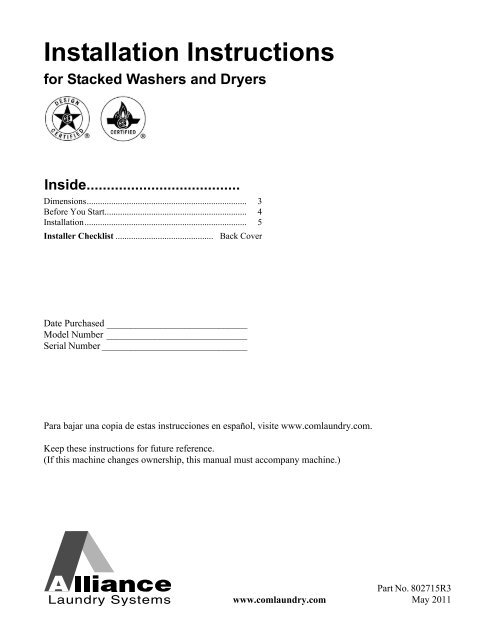
<strong>Installation</strong> <strong>Instructions</strong><br />
<strong>for</strong> <strong>Stacked</strong> <strong>Washers</strong> <strong>and</strong> <strong>Dryers</strong><br />
Inside......................................<br />
Dimensions........................................................................ 3<br />
Be<strong>for</strong>e You Start................................................................ 4<br />
<strong>Installation</strong>......................................................................... 5<br />
Installer Checklist ............................................ Back Cover<br />
Date Purchased _____________________________<br />
Model Number _____________________________<br />
Serial Number ______________________________<br />
Para bajar una copia de estas instrucciones en español, visite www.comlaundry.com.<br />
Keep these instructions <strong>for</strong> future reference.<br />
(If this machine changes ownership, this manual must accompany machine.)<br />
www.comlaundry.com<br />
Part No. 802715R3<br />
May 2011
WARNING<br />
FOR YOUR SAFETY, the in<strong>for</strong>mation in this manual must be followed to minimize the risk<br />
of fire or explosion or to prevent property damage, personal injury or death.<br />
W033<br />
• Do not store or use gasoline or other flammable vapors <strong>and</strong> liquids in the vicinity of this or<br />
any other appliance.<br />
• WHAT TO DO IF YOU SMELL GAS:<br />
– Do not try to light any appliance.<br />
– Do not touch any electrical switch; do not use any phone in your building.<br />
– Clear the room, building or area of all occupants.<br />
– Immediately call your gas supplier from a neighbor’s phone. Follow the gas supplier’s<br />
instructions.<br />
– If you cannot reach your gas supplier, call the fire department.<br />
• <strong>Installation</strong> <strong>and</strong> service must be per<strong>for</strong>med by a qualified installer, service agency or the gas<br />
supplier.<br />
W052<br />
IMPORTANT: Purchaser must consult the local gas supplier <strong>for</strong> suggested instructions to be followed if the<br />
unit user smells gas. The gas utility instructions plus the SAFETY <strong>and</strong> WARNING note directly above must<br />
be posted in a prominent location near the unit <strong>for</strong> customer use.<br />
WARNING<br />
• <strong>Installation</strong> of unit must be per<strong>for</strong>med by a qualified installer.<br />
• Install clothes dryer according to manufacturer’s instructions <strong>and</strong> local codes.<br />
• DO NOT install a clothes dryer with flexible plastic venting materials. If flexible metal (foil<br />
type) duct is installed, it must be of a specific type identified by the appliance manufacturer<br />
as suitable <strong>for</strong> use with clothes dryers. Refer to section on connecting exhaust system.<br />
Flexible venting materials are known to collapse, be easily crushed, <strong>and</strong> trap lint. These<br />
conditions will obstruct clothes dryer airflow <strong>and</strong> increase the risk of fire.<br />
W729R1<br />
•<br />
FOR YOUR SAFETY<br />
Do not store or use gasoline or other flammable vapors <strong>and</strong> liquids in the vicinity of this or<br />
any other appliance.<br />
W053<br />
The following in<strong>for</strong>mation applies to the state of Massachusetts, USA.<br />
• This appliance can only be installed by a Massachusetts licensed plumber or gas fitter.<br />
• This appliance must be installed with a 36 inch (91 cm) long flexible gas connector.<br />
• A “T-H<strong>and</strong>le” type gas shut-off valve must be installed in the gas supply line to this appliance.<br />
• This appliance must not be installed in a bedroom or bathroom.<br />
© Copyright 2011, Alliance Laundry Systems LLC<br />
All rights reserved. No part of the contents of this book may be reproduced or transmitted in any <strong>for</strong>m or by any<br />
means without the expressed written consent of the publisher.<br />
2 © Copyright, Alliance Laundry Systems LLC – DO NOT COPY or TRANSMIT<br />
802715
Dimensions<br />
23.5 in.<br />
(59.7 cm)<br />
8.0 in.<br />
(20.3 cm)<br />
15.4 in.<br />
(39.1 cm)<br />
5.25 in.<br />
(13.3 cm)<br />
*63 in. (160 cm)<br />
*54 in. (137.2 cm)<br />
24 in.<br />
(61 cm)<br />
*13.1 in.<br />
(33.3 cm)<br />
*75.25 in. (191.1 cm)<br />
*44.1 in. (112 cm)<br />
*29.6 in. (75.1 cm)<br />
*31.1 in. (79 cm)<br />
*37.44 in. (95.1 cm)<br />
1.5 in.<br />
(3.81 cm)<br />
28 in.<br />
(71.1 cm)<br />
2.0 in.<br />
(5.1 cm)<br />
26.875 in.<br />
(68.3 cm)<br />
ELECTRIC DRYERS<br />
*14.6 in.<br />
(37.08 cm)<br />
SWD897N<br />
* With leveling legs turned into base.<br />
NOTE: Exhaust openings are 4 inch (10.2 cm) metal ducting.<br />
23.5 in.<br />
(59.7 cm)<br />
8.0 in.<br />
(20.3 cm)<br />
15.4 in.<br />
(39.1 cm)<br />
5.25 in.<br />
(13.3 cm)<br />
1<br />
*63 in. (160 cm)<br />
*54 in. (137.2 cm)<br />
24 in.<br />
(61 cm)<br />
*13.1 in.<br />
(33.3 cm)<br />
*75.25 in. (191.1 cm)<br />
*44.1 in. (112 cm)<br />
2.3 in.<br />
(6 cm)<br />
*29.6 in. (75.1 cm)<br />
*31.1 in. (79 cm)<br />
*42.4 in. (107.7 cm)<br />
*37.44 in. (95.1 cm)<br />
1.5 in.<br />
(3.81 cm)<br />
28 in.<br />
(71.1 cm)<br />
2.0 in.<br />
(5.1 cm)<br />
26.875 in.<br />
(68.3 cm)<br />
GAS DRYERS<br />
*14.6 in.<br />
(37.08 cm)<br />
SWD898N<br />
*With leveling legs turned into base.<br />
NOTE: Exhaust openings are 4 inch (10.2 cm) metal ducting.<br />
1 3/8 in. NPT Gas Connection<br />
802715 © Copyright, Alliance Laundry Systems LLC – DO NOT COPY or TRANSMIT<br />
3
Be<strong>for</strong>e You Start<br />
Supplies<br />
For most installations, the basic supplies you will need<br />
are:<br />
4<br />
1 2 3<br />
5<br />
6<br />
7<br />
WARNING<br />
Any disassembly requiring the use of<br />
tools must be per<strong>for</strong>med by a suitably<br />
qualified service person.<br />
W299<br />
NOTE: If the unit is delivered on a cold day (below<br />
freezing), or is stored in an unheated room or area<br />
during the cold months, do not attempt to operate<br />
it until the unit has had a chance to warm up.<br />
NOTE: Some moisture in the wash drum is normal.<br />
Water is used during testing at the manufacturer.<br />
9/16"<br />
8<br />
9<br />
1 Safety Glasses<br />
2 Wood Block<br />
3 Power Cord (Electric Models)<br />
4 Wrench<br />
5 Screwdriver<br />
6 Level<br />
7 5/16 Inch Socket Wrench<br />
8 Duct Tape<br />
9 Teflon Tape (Gas Models)<br />
DRY2023N<br />
Figure 1<br />
4 © Copyright, Alliance Laundry Systems LLC – DO NOT COPY or TRANSMIT<br />
802715
<strong>Installation</strong><br />
Step 1: Position Unit Near <strong>Installation</strong><br />
Area<br />
Move unit as close to the desired area of installation as<br />
possible.<br />
WARNING<br />
Washer <strong>and</strong> dryer are not designed to be<br />
operated as separated, side-by-side units.<br />
W187<br />
NOTE: For best per<strong>for</strong>mance <strong>and</strong> to minimize<br />
vibration or movement, install washer on a solid,<br />
sturdy <strong>and</strong> level floor. Some floors may need to be<br />
rein<strong>for</strong>ced, especially on a second floor or over a<br />
basement. Do not install the washer on carpeting,<br />
soft tile, a plat<strong>for</strong>m or other weakly supported<br />
structures.<br />
Step 2: Position <strong>and</strong> Level the Unit<br />
Position unit so it has sufficient clearance <strong>for</strong><br />
installation <strong>and</strong> servicing. Refer to Figure 2.<br />
C<br />
D<br />
E<br />
E<br />
A<br />
B<br />
SWD795N<br />
Dryer <strong>and</strong> Exhaust Duct Clearances<br />
Area Description Minimum Clearance<br />
A Left Dryer Side 0 in. (0 cm)<br />
B Right Dryer Side 1 in. (2.54 cm)<br />
C Dryer Top 6 in. (15.24 cm)<br />
D Dryer Rear 4 in. (10.2 cm)<br />
E Exhaust Duct Clearance to Combustible Materials 2 in. (5.1 cm)<br />
NOTE: Shaded areas indicate adjacent structure.<br />
Figure 2<br />
SWD795N<br />
802715 © Copyright, Alliance Laundry Systems LLC – DO NOT COPY or TRANSMIT<br />
5
NOTE: Use of the dispenser drawer or unit doors<br />
as a h<strong>and</strong>le in the transportation of the unit may<br />
cause damage to the dispenser or doors.<br />
Place unit in position on a solid, sturdy <strong>and</strong> level floor.<br />
Installing the unit on any type of carpeting, soft tile, a<br />
plat<strong>for</strong>m or other weakly supported structures is not<br />
recommended.<br />
Place a level on the cabinet top <strong>and</strong> check if the unit is<br />
level from side to side <strong>and</strong> front to back.<br />
NOTE: Level must rest on raised portion of top<br />
panel. Refer to Figure 3.<br />
1<br />
1<br />
5<br />
SWD832N<br />
1 Wood Block<br />
4<br />
3<br />
1 Level<br />
2 Rubber Foot<br />
3 Leveling Leg<br />
4 Locknut<br />
5 Unit Base<br />
2<br />
Figure 3<br />
SWD833N<br />
S<br />
If unit is not level, tilt unit to access the front <strong>and</strong> rear<br />
leveling legs. For easier access to leveling legs, prop<br />
up unit with a wooden block. Refer to Figure 4.<br />
Loosen the locknuts <strong>and</strong> adjust legs by screwing into<br />
or out of unit base.<br />
Figure 4<br />
Make sure that the unit does not rock. When unit is<br />
level <strong>and</strong> does not rock, tighten locknuts securely<br />
against bottom of unit base. If these locknuts are not<br />
tight, unit will move out of position during operation.<br />
Leveling legs can be adjusted from inside the unit with<br />
a 7/8 inch deep well socket. All four legs must rest<br />
firmly on the floor so the weight of the unit is evenly<br />
distributed. The unit must not rock <strong>and</strong> must be level<br />
from side-to-side <strong>and</strong> front-to-back.<br />
NOTE: Do not slide unit across floor once the<br />
leveling legs have been extended. Legs <strong>and</strong> base<br />
could become damaged.<br />
Place rubber feet (supplied in accessories bag) on all<br />
four leveling legs. Refer to Figure 3.<br />
Verify that unit does not rock.<br />
6 © Copyright, Alliance Laundry Systems LLC – DO NOT COPY or TRANSMIT<br />
802715
Step 3: Connect Fill Hoses<br />
Water Supply<br />
WARNING<br />
Under certain conditions, hydrogen gas<br />
may be produced in a hot water system<br />
that has not been used <strong>for</strong> two weeks or<br />
more. HYDROGEN GAS IS EXPLOSIVE. If<br />
the hot water system has not been used<br />
<strong>for</strong> such a period <strong>and</strong> be<strong>for</strong>e using the<br />
washer, turn on all hot water faucets <strong>and</strong><br />
let the water flow from each <strong>for</strong> several<br />
minutes. This will release any<br />
accumulated hydrogen gas. The gas is<br />
flammable. Do not smoke or use an open<br />
flame during this time.<br />
W029<br />
Water supply faucets must fit st<strong>and</strong>ard 3/4 inch<br />
(19.1 mm) female garden hose couplings. DO NOT<br />
USE SLIP-ON OR CLAMP-ON CONNECTIONS.<br />
Water supply faucets should be readily accessible to<br />
permit turning them off when washer is not being<br />
used.<br />
Recommended cold water temperature is 60 o to<br />
80 o Fahrenheit (16 o to 27 o Celsius). Recommended<br />
maximum hot water temperature is 125° Fahrenheit<br />
(51 o Celsius). Warm water is a mixture of hot <strong>and</strong> cold<br />
water. Warm water temperature is dependent upon<br />
water temperature <strong>and</strong> pressure of both the hot <strong>and</strong><br />
cold water supply lines.<br />
NOTE: When installing in newly constructed or<br />
renovated buildings, it is very important to flush<br />
the lines since build-up may have occurred during<br />
construction.<br />
Connecting Hoses<br />
Remove the two plain rubber washers <strong>and</strong> two filter<br />
screens from the accessories bag. Install them into<br />
each end of the fill hoses as shown in Figure 5. The<br />
screen must be facing outward.<br />
Screw hose couplings with the filter screens onto the<br />
water faucets until they are finger-tight. Then, using a<br />
pliers, screw approximately 1/4 turn.<br />
Screw hose couplings from other end of hoses onto the<br />
water mixing valve until they are finger-tight. Then,<br />
using a pliers, screw approximately 1/4 turn. Refer to<br />
Figure 6.<br />
IMPORTANT: Do not cross thread or overtighten<br />
couplings. This will cause them to leak.<br />
Turn water on <strong>and</strong> check <strong>for</strong> leaks. If leaks are found,<br />
turn off the water, unscrew hoses <strong>and</strong> reinstall them<br />
until there are no leaks.<br />
IMPORTANT: Turn off water supply whenever<br />
there will be an extended period of non-use.<br />
HOT<br />
COLD<br />
1<br />
2<br />
3<br />
WARNING<br />
5<br />
To prevent personal injury, avoid contact<br />
with inlet water temperatures higher than<br />
125° Fahrenheit (51° Celsius) <strong>and</strong> hot<br />
surfaces.<br />
W748<br />
Water pressure must be a minimum of 20 to a<br />
maximum of 120 pounds per square inch (138 to<br />
827 kPa) static pressure measured at the faucet.<br />
NOTE: Water pressure under 20 pounds per<br />
square inch (138 kPa) will cause an extended fill<br />
time in the washer <strong>and</strong> may not properly flush out<br />
the detergent dispenser.<br />
1 Water Faucet<br />
2 Fill Hose<br />
3 Plain Rubber Washer<br />
4 Hose Coupling<br />
5 Filter Screens<br />
Figure 5<br />
4<br />
TLW1976N<br />
Turn on the water faucets <strong>and</strong> flush the lines <strong>for</strong><br />
approximately two minutes to remove any <strong>for</strong>eign<br />
material that could clog the screens in the water<br />
mixing valve.<br />
802715 © Copyright, Alliance Laundry Systems LLC – DO NOT COPY or TRANSMIT<br />
7
IMPORTANT: Hoses <strong>and</strong> other natural rubber<br />
parts deteriorate after extended use. Hoses may<br />
develop cracks, blisters or material wear from the<br />
temperature <strong>and</strong> constant high pressure they are<br />
subject to.<br />
All hoses should be checked on a monthly basis <strong>for</strong><br />
any visible signs of deterioration. Any hose showing<br />
the signs of deterioration listed above should be<br />
replaced immediately. All hoses should be replaced<br />
every five years.<br />
Risers<br />
Risers (or air cushions) may have to be installed if the<br />
pipes knock or pound when flow of water stops. The<br />
risers are more efficient when installed as close as<br />
possible to the water supply faucets (refer to Figure 7).<br />
2<br />
1<br />
2<br />
WATER<br />
MIXING VALVE<br />
1<br />
4<br />
SWD596N<br />
3<br />
1 Water Supply Faucets<br />
2 Risers (Air Cushions)<br />
Figure 7<br />
W005I<br />
W005I<br />
SWD596N<br />
1 Water Faucets<br />
2 Cold Water Connection<br />
3 Hot Water Connection<br />
4 Water Fill Hoses<br />
Figure 6<br />
IMPORTANT: Turn off water supply faucets after<br />
check-out <strong>and</strong> demonstration. Owner should turn<br />
off water supply whenever there will be an<br />
extended period of non-use.<br />
NOTE: Longer fill hoses are available (as optional<br />
equipment at extra cost) if the hoses supplied with<br />
the washer are not long enough <strong>for</strong> the installation.<br />
Order hoses as follows:<br />
No. 20617 Fill Hose (8 feet) (2.44 m)<br />
No. 20618 Fill Hose (10 feet) (3.05 m)<br />
8 © Copyright, Alliance Laundry Systems LLC – DO NOT COPY or TRANSMIT<br />
802715
Step 4: Connect Drain Hose to Drain<br />
Receptacle<br />
NOTE: End of drain hose must not be below 24 in.<br />
(61 cm).<br />
Remove the drain hose from its shipping position on<br />
the rear of the washer by unhooking the hose from the<br />
retainer clamp <strong>and</strong> by removing the shipping tape.<br />
Install the drain hose into the drain receptacle<br />
(st<strong>and</strong>pipe, wall or laundry tub) following the<br />
instructions below.<br />
IMPORTANT: Drain receptacle must be capable of<br />
h<strong>and</strong>ling a minimum of 1-1/4 inch (32 cm) outside<br />
diameter drain hose.<br />
St<strong>and</strong>pipe <strong>Installation</strong>:<br />
2<br />
1<br />
Place the drain hose into the st<strong>and</strong>pipe.<br />
Remove the beaded strap from accessories bag <strong>and</strong><br />
place around st<strong>and</strong>pipe <strong>and</strong> drain hose <strong>and</strong> tighten<br />
strap to hold hose to st<strong>and</strong>pipe. Refer to Figure 8. This<br />
will prevent the drain hose from dislodging from drain<br />
receptacle during use.<br />
3<br />
1 Drain Hose<br />
2 Beaded Strap (tape if necessary)<br />
3 Fill Hoses<br />
H023I<br />
1<br />
Figure 9<br />
Laundry Tub <strong>Installation</strong>:<br />
For this type of installation, the drain hose MUST be<br />
secured to the stationary tub to prevent hose from<br />
dislodging during use. Refer to Figure 10. Use the<br />
beaded strap (supplied in accessories bag) to secure<br />
hose.<br />
24 in. to 36 in.<br />
(61 to 91.44 cm)<br />
Recommended<br />
Height<br />
1<br />
2<br />
3<br />
SWD598N<br />
SWD598N<br />
1 Drain Hose<br />
2 Beaded Tie-Down Strap<br />
3 St<strong>and</strong>pipe 2 in. (5.08 cm) or 1-1/2 in. (4 cm)<br />
Wall <strong>Installation</strong>:<br />
Figure 8<br />
For installations of this type, the drain hose MUST be<br />
secured to one of the fill hoses using the beaded strap<br />
from accessories bag. Refer to Figure 9.<br />
2<br />
1 Drain Hose<br />
2 Tie-Down Strap (tape if necessary)<br />
Figure 10<br />
SWD600N<br />
SWD600N<br />
802715 © Copyright, Alliance Laundry Systems LLC – DO NOT COPY or TRANSMIT<br />
9
Step 5: (Gas Dryer Only) Connect Gas<br />
Supply Pipe<br />
WARNING<br />
To reduce the risk of gas leaks, fire or<br />
explosion:<br />
• The dryer must be connected to the type<br />
of gas as shown on nameplate located in<br />
the door recess.<br />
• Use a new flexible stainless steel<br />
connector.<br />
• Use pipe joint compound insoluble in L.P.<br />
(Liquefied Petroleum) Gas, or Teflon tape,<br />
on all pipe threads.<br />
• Purge air <strong>and</strong> sediment from gas supply<br />
line be<strong>for</strong>e connecting it to the dryer.<br />
Be<strong>for</strong>e tightening the connection, purge<br />
remaining air from gas line to dryer until<br />
odor of gas is detected. This step is<br />
required to prevent gas valve<br />
contamination.<br />
• Do not use an open flame to check <strong>for</strong> gas<br />
leaks. Use a non-corrosive leak detection<br />
fluid.<br />
• Any disassembly requiring the use of<br />
tools must be per<strong>for</strong>med by a suitably<br />
qualified service person.<br />
W316<br />
Natural Gas Altitude Adjustments<br />
Altitude Orifice Size<br />
feet m No. inches mm<br />
Part No.<br />
3000 915 43 0.0890 2.26 503778<br />
6000 1830 44 0.0860 2.18 58719<br />
8000 2440 45 0.0820 2.08 503779<br />
9000 2740 46 0.0810 2.06 503780<br />
10,000 3050 47 0.0785 1.99 503781<br />
Table 1<br />
2. Remove the shipping cap from the gas<br />
connection at the rear of the dryer. Make sure you<br />
do not damage the pipe threads when removing<br />
the cap.<br />
3. Connect to gas supply pipe.<br />
NOTE: When connecting to a gas line, an<br />
equipment shut-off valve must be installed within<br />
6 feet (1.8 m) of the dryer. An 1/8 in. NPT pipe plug<br />
must be installed as shown <strong>for</strong> checking inlet<br />
pressure. Refer to Figure 11.<br />
1<br />
1. Make certain your dryer is equipped <strong>for</strong> use with<br />
the type of gas in your laundry room. Dryer is<br />
equipped at the factory <strong>for</strong> Natural Gas with a<br />
3/8 inch NPT gas connection.<br />
NOTE: The gas service to a gas dryer must<br />
con<strong>for</strong>m with the local codes <strong>and</strong> ordinances, or in<br />
the absence of local codes <strong>and</strong> ordinances, with the<br />
latest edition of the National Fuel Gas Code ANSI<br />
Z223.1/NFPA 54 or the CAN/CSA-B149.1 Natural<br />
Gas <strong>and</strong> Propane <strong>Installation</strong> Code.<br />
Natural Gas, 1000 Btu/ft 3 (37.3 MJ/m 3 ) service must<br />
be supplied at minimum 5.0 inch water column<br />
pressure to maximum 10.5 inch water column<br />
pressure.<br />
For proper operation at altitudes above 3000 feet<br />
(915 m) the natural gas valve spud orifice size must be<br />
reduced to ensure complete combustion. Refer to<br />
Table 1.<br />
4<br />
5<br />
1 New stainless steel flexible connector -<br />
(Use design CSA certified connector)<br />
Use only if allowed by local codes<br />
2 1/8 in. NPT Pipe Plug<br />
3 Equipment Shut-Off Valve<br />
4 Black Iron Pipe<br />
Shorter than 20 ft. (6.1 m) -<br />
Use 3/8 in. (9.5 mm) pipe<br />
Longer than 20 ft. (6.1 m) -<br />
Use 1/2 in. (12.7 mm) pipe<br />
5 3/8 in. NPT Gas Connection<br />
2<br />
3<br />
D434I<br />
Figure 11<br />
10 © Copyright, Alliance Laundry Systems LLC – DO NOT COPY or TRANSMIT<br />
802715
4. Tighten all connections securely. Turn on gas <strong>and</strong><br />
check all pipe connections (internal & external)<br />
<strong>for</strong> gas leaks with a non-corrosive leak detection<br />
fluid.<br />
NOTE: The dryer <strong>and</strong> its appliance main gas valve<br />
must be disconnected from the gas supply piping<br />
system during any pressure testing of that system<br />
at test pressures in excess of 1/2 psi (3.45 kPa).<br />
Refer to Step 12 (Check Heat Source).<br />
L.P. (Liquefied Petroleum) Gas, 2500 Btu/ft 3<br />
(93.1 MJ/m 3 ) service must be supplied at 10 ± 1.5 inch<br />
water column pressure.<br />
For proper operation at altitudes above 3000 feet<br />
(915 m) the L.P. gas valve spud orifice size must be<br />
reduced to ensure complete combustion. Refer to<br />
Table 2.<br />
WARNING<br />
To reduce the risk of fire, electric shock,<br />
serious injury or death, all wiring <strong>and</strong><br />
grounding MUST con<strong>for</strong>m with the latest<br />
edition of the National Electrical Code,<br />
ANSI/NFPA 70, or the Canadian Electrical<br />
Code, CSA C22.1, <strong>and</strong> such local<br />
regulations as might apply. It is the<br />
customer’s responsibility to have the wiring<br />
<strong>and</strong> fuses installed by a qualified electrician<br />
to make sure adequate electrical power is<br />
available to the dryer.<br />
W521<br />
L.P. Altitude Adjustments<br />
Altitude Orifice Size<br />
feet m No. inches mm<br />
Part No.<br />
3000 915 55 0.0520 1.32 58755<br />
8000 2440 56 0.0465 1.18 503786<br />
Table 2<br />
NOTE: DO NOT connect the dryer to L.P. Gas<br />
Service without converting the gas valve. Install<br />
L.P. Gas Conversion Kit 649P3, available at extra<br />
cost.<br />
Step 6: (Electric Dryer Only) Connect<br />
Electrical Plug<br />
NOTE: Model LTSA7A*N2989 - A single electrical<br />
connection serves both washer <strong>and</strong> dryer.<br />
Dryer requires 120/240 Volt or 120/208 Volt, 60 Hertz,<br />
3 or 4 wire electrical supply. Refer to serial plate <strong>for</strong><br />
specific electrical requirements.<br />
NOTE: The wiring diagram is located behind the<br />
control panel, inside the control cabinet.<br />
802715 © Copyright, Alliance Laundry Systems LLC – DO NOT COPY or TRANSMIT<br />
11
Grounding In<strong>for</strong>mation<br />
• This dryer must be connected to a grounded<br />
metal, permanent wiring system; or an<br />
equipment-grounding conductor must be run<br />
with the circuit conductors <strong>and</strong> connected to the<br />
equipment-grounding terminal or lead on the<br />
dryer.<br />
• For model LTSA7A*N2989, only flexible metal<br />
conduit, rigid metal conduit or armored cable<br />
wiring systems are recommended.<br />
• The dryer has its own terminal block (on model<br />
LTSA7A*N2989 powers both washer <strong>and</strong> dryer)<br />
that must be connected to a separate branch, 60<br />
Hertz, single phase circuit, AC (alternating<br />
current) circuit, fused at 30 Amperes (the circuit<br />
must be fused on both sides of the line).<br />
Electrical service <strong>for</strong> the dryer should be of<br />
maximum rated voltage (208 or 240 Volt,<br />
depending on heating element) listed on the<br />
nameplate. Do not connect dryer to 110, 115,<br />
or 120 volt circuit.<br />
• Heating elements are available <strong>for</strong> field<br />
installation in dryers which are to be connected to<br />
electrical service of different voltage than that<br />
listed on nameplate, such as 208 Volt.<br />
NOTE: Branch circuit wire size requirements to<br />
laundry room outlet are shown in Table 3 <strong>and</strong><br />
Table 4.<br />
Wire Length<br />
Less than<br />
15 ft. (4.5 m)<br />
Longer than<br />
15 ft. (4.5 m)<br />
Wire Length<br />
Less than<br />
15 ft. (4.5 m)<br />
Longer than<br />
15 ft. (4.5 m)<br />
Model LTSA7A*N2989<br />
All Other Models<br />
Wire<br />
Listed No. 8 AWG<br />
Copper wire only<br />
Listed No. 6 AWG<br />
Copper wire only<br />
Table 3<br />
Wire<br />
Listed No. 10 AWG<br />
Copper wire only<br />
Listed No. 8 AWG<br />
Copper wire only<br />
Table 4<br />
• The power cord connection between wall<br />
receptacle <strong>and</strong> dryer terminal block IS NOT<br />
supplied with dryer. Type of power cord <strong>and</strong><br />
gauge of wire must con<strong>for</strong>m to local codes.<br />
12 © Copyright, Alliance Laundry Systems LLC – DO NOT COPY or TRANSMIT<br />
802715
Connecting Power Cord with Three-Wire<br />
Plug<br />
NOTE: Four-wire cord is required <strong>for</strong> mobile<br />
homes or where codes do not permit grounding<br />
through neutral.<br />
NOTE: The power cord is NOT supplied with the<br />
electric dryer. Type of power cord <strong>and</strong> gauge of wire<br />
must con<strong>for</strong>m to local codes <strong>and</strong> instructions.<br />
POWER SUPPLY<br />
POWER SUPPLY<br />
The method of wiring the dryer is optional <strong>and</strong> subject<br />
to local code requirements.<br />
NOTE: Connect the dryer to the power supply with the<br />
MAXIMUM RATED VOLTAGE listed on the nameplate.<br />
1<br />
2<br />
3<br />
A typical 30-<br />
Amp Three-<br />
Wire<br />
Receptacle<br />
NEMA Type<br />
10-30R<br />
INTERMEDIATE FUSE<br />
BOX (may be omitted<br />
if service entrance<br />
box is fused)<br />
4<br />
INTERMEDIATE<br />
SHUT-OFF BOX<br />
(may or may not<br />
be fused)<br />
120 ± 12<br />
V.A.C.<br />
120 ± 12<br />
V.A.C.<br />
240 ± 12<br />
V.A.C.<br />
WALL<br />
RECEPTACLE<br />
5<br />
6<br />
7<br />
NOTE: Use COPPER WIRE only.<br />
Shorter than 15 ft. (4.5 m) – use 10 AWG<br />
Longer than 15 ft. (4.5 m) – use 8 AWG<br />
L1 L2 L1 L2<br />
POWER CORD CONNECTION<br />
DIRECT CONNECTION<br />
1 3 Wire Grounded Neutral 120/240 Volt, 60 Hertz<br />
AC 1 Phase Service Entrance Switch Box<br />
(Refer to NOTE above)<br />
4 Metallic or Non-Metallic Sheathed Cable<br />
(Copper Wire Only)<br />
5 Power Cord (Not supplied with dryer)<br />
2 30 Ampere Fuses or Circuit Breaker 6 Neutral<br />
3 Neutral Wire 7 Terminal Block in Dryer<br />
D816I<br />
1. Disconnect power to dryer.<br />
2. Remove access cover from rear of dryer.<br />
Figure 12<br />
3. Use a strain relief <strong>and</strong> insert end of power cord<br />
through power supply hole.<br />
D696I<br />
Figure 13<br />
D695I<br />
Figure 14<br />
802715 © Copyright, Alliance Laundry Systems LLC – DO NOT COPY or TRANSMIT<br />
13
4. Use the three screws from the accessories bag to<br />
attach the power cord wires to the terminal block.<br />
Refer to Figure 15.<br />
1 2<br />
Connecting Power Cord with Four-Wire Plug<br />
NOTE: Four-wire cord is required <strong>for</strong> mobile<br />
homes or where codes do not permit grounding<br />
through neutral.<br />
1<br />
2<br />
3<br />
3<br />
4<br />
1 “L1” Terminal<br />
2 Neutral Terminal<br />
3 “L2” Terminal<br />
Figure 15<br />
D286I<br />
120 ± 12<br />
V.A.C.<br />
120 ± 12<br />
V.A.C.<br />
120 ± 12<br />
V.A.C.<br />
240 ± 12<br />
V.A.C.<br />
120 ± 12<br />
V.A.C.<br />
0<br />
V.A.C.<br />
5. Tighten all screws firmly.<br />
IMPORTANT: Failure to tighten these screws<br />
firmly may result in wire failure at the terminal<br />
block.<br />
6. Secure the strain relief to the power cord, or<br />
wires, where they enter the dryer cabinet.<br />
7. Check the continuity of the ground connection<br />
be<strong>for</strong>e plugging the cord into an outlet. Use an<br />
acceptable indicating device connected to the<br />
center grounding pin of the plug <strong>and</strong> the green<br />
screw on the back of the cabinet.<br />
1 Typical Four-Wire Receptacle<br />
2 Power Cord – Not Supplied with Dryer<br />
3 Strain Relief Nut<br />
4 Strain Relief<br />
Figure 16<br />
1. Disconnect power to dryer.<br />
2. Remove access cover from rear of dryer.<br />
DRY2016N<br />
8. Reinstall access cover <strong>and</strong> screw.<br />
D695I<br />
D695I<br />
Figure 17<br />
14 © Copyright, Alliance Laundry Systems LLC – DO NOT COPY or TRANSMIT<br />
802715
3. Remove ground screw <strong>and</strong> save <strong>for</strong> use in Step 5.<br />
Remove wire <strong>and</strong> use in Step 6.<br />
5. Attach power cord ground (green) wire to rear<br />
bulkhead using ground screw removed in Step 3.<br />
1<br />
7<br />
1<br />
6<br />
5<br />
1 Ground Screw<br />
D697I<br />
D697I<br />
4<br />
3<br />
2<br />
DRY1920N<br />
Figure 18<br />
4. Use a strain relief <strong>and</strong> insert end of power cord<br />
through power supply hole.<br />
1 White<br />
2 “L2” Terminal<br />
3 Black<br />
4 Green<br />
5 Red<br />
6 Neutral Terminal<br />
7 “L1” Terminal<br />
DRY1920N<br />
Figure 19<br />
D696I<br />
Figure 20<br />
6. Use the three screws from the accessories bag to<br />
attach the remaining power cord wires to the<br />
terminal block as follows:<br />
a. Red wire to “L1” terminal.<br />
b. Black wire to “L2” terminal.<br />
c. White wire to Neutral terminal.<br />
NOTE: All models except LTSA7A*N2989, when<br />
installing the white wire, loop the free eyelet end of<br />
the ground wire (removed in Step 3) <strong>and</strong> attach<br />
along with the white wire to the neutral (center)<br />
terminal on the terminal block.<br />
7. Tighten all screws firmly.<br />
IMPORTANT: Failure to tighten these screws<br />
firmly may result in wire failure at the terminal<br />
block.<br />
8. Secure the strain relief to the power cord, or<br />
wires, where they enter the dryer cabinet.<br />
9. Check the continuity of the ground connection<br />
be<strong>for</strong>e plugging the cord into an outlet. Use an<br />
acceptable indicating device connected to the<br />
center grounding pin of the plug <strong>and</strong> the green<br />
screw on the back of the cabinet.<br />
10. Reinstall access cover <strong>and</strong> screw.<br />
802715 © Copyright, Alliance Laundry Systems LLC – DO NOT COPY or TRANSMIT<br />
15
Step 7: Connect Dryer Exhaust System<br />
WARNING<br />
To reduce the risk of fire <strong>and</strong> combustion<br />
gas accumulation the dryer MUST be<br />
exhausted to the outdoors.<br />
W604<br />
To reduce the risk of fire <strong>and</strong> the<br />
accumulation of combustion gases, DO<br />
NOT exhaust dryer air into a window well,<br />
gas vent, chimney or enclosed, unventilated<br />
area, such as an attic, wall, ceiling, crawl<br />
space under a building or concealed space<br />
of a building.<br />
W045<br />
WARNING<br />
This gas appliance contains or produces a<br />
chemical or chemicals which can cause<br />
death or serious illness <strong>and</strong> which are<br />
known to the State of Cali<strong>for</strong>nia to cause<br />
cancer, birth defects, or other reproductive<br />
harm. To reduce the risk from substances in<br />
the fuel or from fuel combustion, make sure<br />
this appliance is installed, operated, <strong>and</strong><br />
maintained according to the instructions in<br />
this manual.<br />
W115<br />
To reduce the risk of fire, DO NOT use<br />
plastic or thin foil ducting to exhaust the<br />
dryer.<br />
W354<br />
• DO NOT use plastic or thin foil ducting. Rigid<br />
metal duct is recommended. Refer to Figure 21.<br />
• Locate dryer so exhaust duct is as short as<br />
possible.<br />
• Be certain old ducts are cleaned be<strong>for</strong>e installing<br />
your new dryer.<br />
• Use 4 inch (102 mm) diameter rigid or flexible<br />
metal duct.<br />
• The male end of each section of duct must point<br />
away from the dryer.<br />
• Use as few elbows as possible.<br />
• Use duct tape or pop-rivets on all duct joints. DO<br />
NOT use sheet metal screws or fasteners on<br />
exhaust pipe joints which extend into the duct<br />
<strong>and</strong> catch lint.<br />
• Ductwork that runs through unheated areas must<br />
be insulated to help reduce condensation <strong>and</strong> lint<br />
build-up on pipe walls.<br />
• In mobile home installations, dryer exhaust duct<br />
must be secured to mobile home structure.<br />
• Dryer exhaust duct MUST NOT terminate under<br />
mobile home.<br />
• Dryer exhausts 220 cfm (measured at back of<br />
dryer).<br />
• DO NOT install flexible duct in concealed<br />
spaces, such as a wall or ceiling.<br />
• Static pressure in exhaust duct should not be<br />
greater than .6 inches water column (1.5 cm),<br />
measured with manometer placed on exhaust<br />
duct two feet (61 cm) from dryer (check with<br />
dryer running <strong>and</strong> no load).<br />
• Exhausting dryer in hard-to-reach locations can<br />
be done by installing 521P3 Flexible Metal Vent<br />
Kit (available as optional equipment at extra<br />
cost).<br />
• Sufficient make-up air must be supplied to<br />
replace the air exhausted by the dryer. The free<br />
area of any opening <strong>for</strong> outside air must be at<br />
least 40 in. 2 (260 cm 2 ).<br />
• Failure to exhaust dryer properly will void<br />
warranty.<br />
NOTE: Venting materials are not supplied with the<br />
dryer (obtain locally).<br />
IMPORTANT: DO NOT block the airflow at the<br />
bottom of the dryer’s front panel with laundry,<br />
rugs, etc. Blockage will decrease airflow through<br />
the dryer, thus reducing the efficiency of the dryer.<br />
DO<br />
DON’T<br />
SWD449N<br />
SWD449N<br />
Figure 21<br />
16 © Copyright, Alliance Laundry Systems LLC – DO NOT COPY or TRANSMIT<br />
802715
Exhaust Direction<br />
The dryer can be exhausted to the outdoors through the<br />
back, left, right or bottom of the dryer. EXCEPTION:<br />
Gas dryers cannot be vented out the left side<br />
because of the burner housing.<br />
Dryer is shipped from factory ready <strong>for</strong> rear exhaust.<br />
Exhausting the dryer through sides or bottom can be<br />
accomplished by installing a Directional Exhaust Kit,<br />
528P3, available as optional equipment at extra cost.<br />
Exhaust System<br />
For best drying results, recommended maximum<br />
length of exhaust system is shown in Table 5.<br />
To prevent backdraft when dryer is not in operation,<br />
outer end of exhaust pipe must have a weather hood<br />
with hinged dampers (obtain locally).<br />
NOTE: Weather hood should be installed at least<br />
12 inches (30.5 cm) above the ground. Larger<br />
clearances may be necessary <strong>for</strong> installations where<br />
heavy snowfall can occur.<br />
Number of<br />
90° Elbows<br />
Recommended<br />
Weather Hood Type<br />
Use Only <strong>for</strong> Short Run installations<br />
4 in.<br />
(10.2 cm)<br />
4 in.<br />
(10.2 cm)<br />
D673I<br />
2-1/2 in.<br />
(6.35 cm)<br />
D802I<br />
Maximum length of 4 in. (10.2 cm) diameter rigid metal duct.<br />
0 65 feet (19.8 m) 55 feet (16.8 m)<br />
1 55 feet (16.8 m) 47 feet (14.3 m)<br />
2 47 feet (14.3 m) 41 feet (12.5 m)<br />
3 36 feet (11.0 m) 30 feet (9.1 m)<br />
4 28 feet (8.5 m) 22 feet (6.7 m)<br />
NOTE: Deduct 6 feet (1.8 m) <strong>for</strong> each additional elbow.<br />
Table 5<br />
NOTE: The maximum length of a 4 in. (10.2 cm)<br />
diameter flexible metal duct must not exceed<br />
7.87 ft. (2.4 m), as required to meet UL2158, clause<br />
7.3.2A.<br />
802715 © Copyright, Alliance Laundry Systems LLC – DO NOT COPY or TRANSMIT<br />
17
Step 8: (Washer Only) Remove the Shock<br />
Sleeves <strong>and</strong> Shipping Brace<br />
Remove front access panel by removing the two<br />
screws at the bottom of the panel.<br />
Remove the five bolts <strong>and</strong> lockwashers from shipping<br />
brace with 9/16 inch wrench <strong>and</strong> remove brace. Refer<br />
to Figure 22. One is holding the brace to the weight.<br />
Remove this bolt first. Four bolts are located on the<br />
unit base. Remove the two front bolts next <strong>and</strong> then<br />
the two rear bolts. Remove all four shock sleeves by<br />
pulling on the yellow rope. Refer to Figure 22.<br />
Remove the brace from the machine with shock<br />
sleeves <strong>and</strong> label attached to it.<br />
IMPORTANT: The shipping brace, bolts,<br />
lockwashers <strong>and</strong> shock sleeves should be saved <strong>and</strong><br />
MUST be reinstalled whenever the unit is moved<br />
more than 4 ft. (1.22 m). Do not lift or transport<br />
unit from front or without shipping materials<br />
installed. Refer to the Washer User’s Guide <strong>for</strong><br />
proper instructions on reinstalling the shipping<br />
materials.<br />
Store the shipping materials in the accessories bag.<br />
Save materials <strong>for</strong> use whenever the unit is moved.<br />
On older models, remove label from front side of front<br />
access panel <strong>and</strong> place on back side of front access<br />
panel <strong>for</strong> future reference.<br />
IMPORTANT: DO NOT tip washer more than<br />
6 inches (152.4 mm) in any direction after shipping<br />
brace has been removed. Shock absorbers may<br />
separate <strong>and</strong> damage to unit may result. For<br />
leveling purposes, the unit may be tilted a<br />
maximum of 6 inches (152.4 mm) in any direction.<br />
Step 9: Wipe Out Inside of Washer Drum<br />
<strong>and</strong> Dryer Drum<br />
Be<strong>for</strong>e using the washer <strong>and</strong> dryer <strong>for</strong> the first time,<br />
use an all-purpose cleaner, or a detergent <strong>and</strong> water<br />
solution, <strong>and</strong> a damp cloth to remove shipping dust<br />
from inside the drums.<br />
Figure 23<br />
SWD834N<br />
1<br />
2<br />
3<br />
1 Shock Sleeves<br />
2 Motor Mount<br />
3 Hooked End of Shipping Brace<br />
4 Bolts <strong>and</strong> Lockwashers<br />
Figure 22<br />
Reinstall front access panel.<br />
4<br />
FLW2124N<br />
FLW2124N<br />
Figure 24<br />
SWD603N<br />
18 © Copyright, Alliance Laundry Systems LLC – DO NOT COPY or TRANSMIT<br />
802715
Step 10: Plug In the Washer <strong>and</strong> Dryer<br />
Electric Dryer<br />
Connect the dryer to an electrical power source. Refer<br />
to Step 4 <strong>for</strong> in<strong>for</strong>mation on connecting power cord.<br />
Gas Dryer<br />
Connect to 30 Amp circuit.<br />
Figure 25<br />
Dryer requires 120 Volt, 60 Hertz electrical supply <strong>and</strong><br />
comes equipped with a 3-prong grounding plug. Refer<br />
to serial plate <strong>for</strong> specific electrical requirements.<br />
NOTE: The wiring diagram is located behind the<br />
control panel, inside the control cabinet.<br />
WARNING<br />
When plugging in the dryer:<br />
• Do not overload circuits.<br />
• Do not use an adapter.<br />
• Do not use an extension cord.<br />
• Do not operate both a washer <strong>and</strong> gas dryer on<br />
the same circuit. Use separately fused 15 amp<br />
circuits.<br />
D275I<br />
To reduce the risk of fire, electric shock,<br />
serious injury or death, all wiring <strong>and</strong><br />
grounding MUST con<strong>for</strong>m with the latest<br />
edition of the National Electrical Code,<br />
ANSI/NFPA 70, or the Canadian Electrical<br />
Code, CSA C22.1, <strong>and</strong> such local<br />
regulations as might apply. It is the<br />
customer’s responsibility to have the wiring<br />
<strong>and</strong> fuses installed by a qualified electrician<br />
to make sure adequate electrical power is<br />
available to the dryer.<br />
W521<br />
The dryer is designed to be operated on a separate<br />
branch, polarized, three-wire, effectively grounded,<br />
120 Volt, 60 Hertz, AC (alternating current) circuit<br />
protected by a 15 Ampere fuse, equivalent fusetron or<br />
circuit breaker.<br />
The three-prong grounding plug on the power cord<br />
should be plugged directly into a polarized three-slot<br />
effectively grounded receptacle rated 120 Volts AC<br />
(alternating current) 15 Amps. Refer to Figure 26 to<br />
determine correct polarity of the wall receptacle.<br />
Grounding In<strong>for</strong>mation<br />
The dryer must be grounded. In the event of<br />
malfunction or breakdown, grounding will reduce the<br />
risk of electric shock by providing a path of least<br />
resistance <strong>for</strong> electric current. The dryer is equipped<br />
with a cord having an equipment-grounding conductor<br />
<strong>and</strong> a 3 prong grounding plug. The three-prong<br />
grounding plug on the power cord should be plugged<br />
directly into a polarized three-slot effectively<br />
grounded receptacle rated 110/120 Volts AC<br />
(alternating current) 15 Amps.<br />
WARNING<br />
This dryer is equipped with a three-prong<br />
(grounding) plug <strong>for</strong> your protection<br />
against shock hazard <strong>and</strong> should be<br />
plugged directly into a properly grounded<br />
three-prong receptacle. Do not cut or<br />
remove the grounding prong from this plug.<br />
W036<br />
WARNING<br />
Improper connection of the equipmentgrounding<br />
conductor can result in a risk of<br />
electric shock. Check with a qualified<br />
electrician or service person if you are in<br />
doubt as to whether the dryer is properly<br />
grounded.<br />
W038<br />
Do not modify the plug provided with the dryer – if it<br />
will not fit the outlet, have a proper outlet installed by<br />
a qualified electrician.<br />
NOTE: Have a qualified electrician check the<br />
polarity of the wall receptacle. If a voltage reading<br />
is measured other than that illustrated, the<br />
qualified electrician should correct the problem.<br />
Do not operate other appliances on the same circuit<br />
when this appliance is operating.<br />
802715 © Copyright, Alliance Laundry Systems LLC – DO NOT COPY or TRANSMIT<br />
19
WARNING<br />
To reduce the risk of an electric shock or<br />
fire, DO NOT use an extension cord or an<br />
adapter to connect the dryer to the electrical<br />
power source.<br />
W037<br />
Washer - All Models Except LTSA7A*N2989<br />
Washer requires 120 Volt, 60 Hertz electrical supply<br />
<strong>and</strong> comes equipped with a 3-prong grounding plug.<br />
Refer to serial plate <strong>for</strong> specific electrical<br />
requirements.<br />
NOTE: The wiring diagram is located behind the<br />
control panel, inside the control cabinet.<br />
1<br />
2<br />
3<br />
120±12<br />
V.A.C.<br />
1<br />
2<br />
3<br />
0 V.A.C.<br />
120±12<br />
V.A.C<br />
0 V.A.C<br />
D254I<br />
120±12<br />
V.A.C.<br />
4<br />
5<br />
120±12<br />
V.A.C<br />
4<br />
St<strong>and</strong>ard 120 Volt, 60<br />
Hertz 3-Wire Effectively<br />
Grounded Circuit<br />
5<br />
1 L1<br />
2 Ground<br />
3 Neutral Side<br />
4 Round Grounding Prong<br />
5 Neutral<br />
DRY2022N<br />
Plug cord into separately fused 15 Amp circuit. DRY2<br />
1 “L1”<br />
2 Ground<br />
3 Neutral<br />
4 Neutral Side<br />
5 Round Grounding Prong<br />
Figure 26<br />
DRY2022N<br />
Figure 27<br />
WARNING<br />
To reduce the risk of fire, electric shock,<br />
serious injury or death, all wiring <strong>and</strong><br />
grounding MUST con<strong>for</strong>m with the latest<br />
edition of the National Electrical Code,<br />
ANSI/NFPA No. 70, <strong>and</strong> such local<br />
regulations as might apply. It is the<br />
customer’s responsibility to have the<br />
wiring, fuses <strong>and</strong> circuit breakers<br />
installed by a qualified electrician to make<br />
sure adequate electrical power is<br />
available to the washer.<br />
W518<br />
20 © Copyright, Alliance Laundry Systems LLC – DO NOT COPY or TRANSMIT<br />
802715
When plugging in the washer:<br />
• DO NOT overload circuits.<br />
• DO NOT use an extension cord.<br />
• DO NOT use an adapter.<br />
• DO NOT operate both a washer <strong>and</strong> gas dryer on<br />
the same circuit. Use separately fused 15 Amp<br />
circuits.<br />
The washer is designed to be operated on a separate<br />
branch, polarized, three-wire, effectively grounded,<br />
120 Volt, 60 Hertz, AC (alternating current) circuit<br />
protected by a 15 Amp fuse, equivalent fusetron or<br />
circuit breaker.<br />
The three-prong grounding plug on the power cord<br />
should be plugged directly into a polarized three-slot<br />
effectively grounded receptacle rated 110/120 Volts<br />
AC (alternating current) 15 Amps. Refer to Figure 27<br />
to determine correct polarity of the wall receptacle.<br />
Grounding In<strong>for</strong>mation<br />
WARNING<br />
To reduce the risk of an electric shock or<br />
fire, DO NOT use an extension cord or an<br />
adapter to connect the washer to the<br />
electric power source.<br />
W082<br />
The washer must be grounded. In the event of<br />
malfunction or breakdown, grounding will reduce the<br />
risk of electric shock by providing a path of least<br />
resistance <strong>for</strong> electric current.<br />
The washer is equipped with a cord having an<br />
equipment-grounding conductor <strong>and</strong> a 3-prong<br />
grounding plug. The plug must be plugged into an<br />
appropriate outlet that is properly installed <strong>and</strong><br />
grounded in accordance with all local codes <strong>and</strong><br />
ordinances.<br />
WARNING<br />
Improper connection of the equipmentgrounding<br />
conductor can result in a risk<br />
of electric shock. Check with a qualified<br />
electrician or service person if you are in<br />
doubt as to whether the washer is<br />
properly grounded.<br />
W216<br />
NOTE: Have a qualified electrician check the<br />
polarity of the wall receptacle. If a voltage reading<br />
is measured other than that in Figure 27, the<br />
qualified electrician should correct the problem.<br />
WARNING<br />
This unit is equipped with a three-prong<br />
(grounding) plug <strong>for</strong> your protection<br />
against shock hazard <strong>and</strong> should be<br />
plugged directly into a properly grounded<br />
three-prong receptacle. Do not cut or<br />
remove the grounding prong from this<br />
plug.<br />
W213<br />
Step 11: Recheck steps 1-10<br />
Refer to Installer Checklist on the back cover of this<br />
manual <strong>and</strong> make sure that unit is installed correctly.<br />
Run washer through one complete cycle to make sure<br />
it is operating properly.<br />
Step 12: Check Heat Source<br />
Electric <strong>Dryers</strong><br />
Close the loading door <strong>and</strong> start the dryer in a heat<br />
setting (refer to the Dryer User’s Guide supplied with<br />
the unit). After the dryer has operated <strong>for</strong> three<br />
minutes, the exhaust air or exhaust pipe should be<br />
warm.<br />
Gas <strong>Dryers</strong><br />
IMPORTANT: This operation is to be conducted<br />
by qualified personnel only.<br />
To view the burner flame, remove the lower front<br />
panel of the dryer.<br />
Close the loading door, start the dryer in a heat setting<br />
(refer to the Dryer User’s Guide supplied with the<br />
unit); the unit will start, the igniter will glow red <strong>and</strong><br />
the main burner will ignite.<br />
IMPORTANT: If all air is not purged out of gas<br />
line, gas igniter may go off be<strong>for</strong>e gas is ignited. If<br />
this happens, after approximately two minutes<br />
igniter will again attempt gas ignition.<br />
IMPORTANT: If igniter does not light, make sure<br />
gas is turned on.<br />
Do not modify the plug provided with the washer – if<br />
it will not fit the outlet, have a proper outlet installed<br />
by a qualified electrician.<br />
802715 © Copyright, Alliance Laundry Systems LLC – DO NOT COPY or TRANSMIT<br />
21
After the dryer has operated <strong>for</strong> approximately five<br />
minutes, observe burner flame through lower front<br />
panel. Adjust the air shutter to obtain a soft, uni<strong>for</strong>m<br />
blue flame. (A lazy, yellow-tipped flame indicates lack<br />
of air. A harsh, roaring, very blue flame indicates too<br />
much air.) Adjust the air shutter as follows:<br />
1. Loosen the air shutter lockscrew.<br />
2. Turn the air shutter to the left to get a luminous<br />
yellow-tipped flame, then turn it back slowly to<br />
the right to obtain a steady, soft blue flame.<br />
3. After the air shutter is adjusted <strong>for</strong> proper flame,<br />
tighten the air shutter lockscrew securely.<br />
4. Reinstall the lower front panel.<br />
WARNING<br />
For personal safety, lower front panel must<br />
be in place during normal operation.<br />
W046<br />
After the dryer has operated <strong>for</strong> approximately three<br />
minutes, exhaust air or exhaust pipe should be warm.<br />
1<br />
2<br />
4<br />
3<br />
1 Air Shutter Lockscrew 3 Air Shutter<br />
2 Appliance Main Gas Valve 4 1/8 in. (3.1 mm) Pipe Plug<br />
(For checking manifold pressure)<br />
D702I<br />
D702I<br />
Figure 28<br />
22 © Copyright, Alliance Laundry Systems LLC – DO NOT COPY or TRANSMIT<br />
802715
Installer Checklist<br />
Fast Track <strong>for</strong> Installing the Unit<br />
(Refer to the manual <strong>for</strong> more detailed in<strong>for</strong>mation)<br />
1<br />
• Position Unit Near<br />
<strong>Installation</strong> Area.<br />
CHECK<br />
7<br />
• Connect Dryer<br />
Exhaust System.<br />
2<br />
• Position <strong>and</strong><br />
Level the Unit.<br />
CHECK<br />
SWD833N<br />
SWD833N<br />
8<br />
CHECK<br />
Washer Only<br />
• Remove the Shock<br />
Sleeves <strong>and</strong><br />
Shipping Brace.<br />
SWD449N<br />
3<br />
• Connect Fill<br />
Hoses.<br />
CHECK<br />
Filter<br />
Screens<br />
HOT<br />
COLD<br />
Plain<br />
<strong>Washers</strong><br />
TLW1976N<br />
TLW1976N<br />
9<br />
CHECK<br />
• Wipe Out Inside<br />
of Washer<br />
<strong>and</strong> Dryer.<br />
FLW2124N<br />
4<br />
• Connect Drain<br />
Hose to Drain<br />
Receptacle.<br />
10<br />
CHECK<br />
SWD834N<br />
SWD834N<br />
• Plug In Washer <strong>and</strong> Dryer.<br />
SWD603N<br />
SWD603N<br />
5<br />
CHECK<br />
Gas Only<br />
• Connect Gas Supply Pipe.<br />
• Check <strong>for</strong> Gas Leaks.<br />
SWD598N<br />
11<br />
D275I<br />
D254I<br />
D254I<br />
ELECTRIC DRYERS GAS DRYERS AND WASHERS<br />
CHECK<br />
• Recheck Steps 1-10.<br />
CHECK<br />
D434I<br />
CHECK<br />
6<br />
Electric Only<br />
• Connect Electrical<br />
Cords.<br />
12<br />
• Check Heat<br />
Source.<br />
CHECK<br />
D679IE0A<br />
D679IEOA<br />
CHECK<br />
D702I<br />
© Copyright, Alliance Laundry Systems LLC – DO NOT COPY or TRANSMIT