CONTENTS - Precision Power
CONTENTS - Precision Power
CONTENTS - Precision Power

Create successful ePaper yourself
Turn your PDF publications into a flip-book with our unique Google optimized e-Paper software.
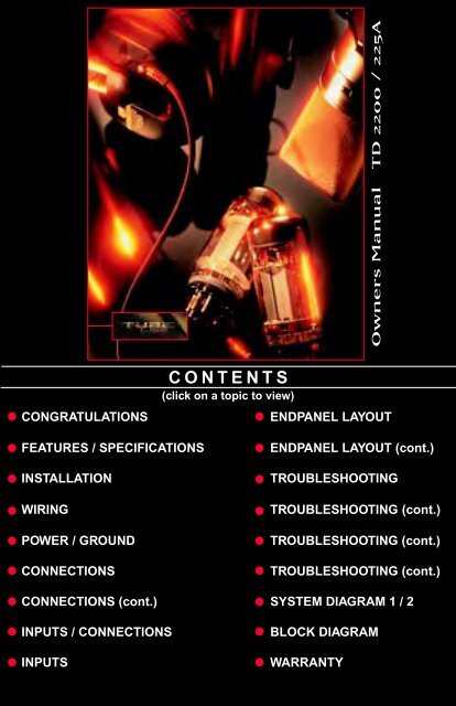
Owners Manual TD 2200 / 225A<br />
CONGRATULATIONS<br />
<strong>CONTENTS</strong><br />
(click on a topic to view)<br />
ENDPANEL LAYOUT<br />
FEATURES / SPECIFICATIONS<br />
INSTALLATION<br />
WIRING<br />
POWER / GROUND<br />
CONNECTIONS<br />
ENDPANEL LAYOUT (cont.)<br />
TROUBLESHOOTING<br />
TROUBLESHOOTING (cont.)<br />
TROUBLESHOOTING (cont.)<br />
TROUBLESHOOTING (cont.)<br />
CONNECTIONS (cont.) SYSTEM DIAGRAM 1 / 2<br />
INPUTS / CONNECTIONS<br />
INPUTS<br />
BLOCK DIAGRAM<br />
WARRANTY
Thank you for choosing TUBE DRIVER. Tube Drivers musicality and absolute sonic<br />
transparency allow accurate reproduction of recorded music enabling you to hear as well as<br />
feel the music the way the artist intended. These handcrafted amplifiers feature full differential<br />
“front ends” based upon a true instrumentation amplifier topology. Tube Drivers utilize only<br />
the highest quality Svetlana tubes in our unique configurations. All of the internal amplifier<br />
stages have been designed to have ultra-wide bandwidth together with a high degree of<br />
linearity. The tubes used in these amplifiers provide both voltage gain and current gain where<br />
they are connected in Cascode and Cathode Follower configurations. D.C. servos are used<br />
to control any D.C. offset. These servos are critically positioned in the circuit so that not only<br />
is D.C. offset eliminated but also any subtle differences between tubes are internally<br />
compensated. These tube stages are then connected to a high current BiPolar output stage<br />
that uses the same audiophile quality Sanken output devices featured in the <strong>Precision</strong><strong>Power</strong><br />
2500F1.The output stages receive their power from a highly regulated D.C. power supply<br />
which enhances their performance significantly. Very little negative feedback is used. Low<br />
feedback designs have greatly improved sound quality having an extremely warm and open<br />
sound with enhanced musicality consistent with only the highest quality home tube amplifiers.<br />
Service<br />
Do not attempt to service TUBE DRIVER products yourself.<br />
Performing exploratory surgery on your audio equipment yourself<br />
will void the warranty. Many parts of your TUBE DRIVER gear<br />
are custom built to our specifications. Our factory parts are not<br />
made available to anyone else nor are they for sale. Our goal<br />
is to make sure that your TUBE DRIVER product will always<br />
sound as good as the day it was purchased. Contact your<br />
authorized TUBE DRIVER dealer about obtaining any warranty<br />
service through TUBE DRIVER.(See Warranty insde back cover)<br />
M o d e l<br />
Serial Number<br />
Purchase Date<br />
FOR YOUR RECORDS<br />
Caution!<br />
The extended use of a high powered audio system may<br />
result in hearing loss or damage. While TUBE DRIVER<br />
systems are capable of "Concert Level" volumes with<br />
incredible accuracy, they are also designed for you to<br />
enjoy at more reasonable levels all of the sonic subtleties<br />
created by musicians. Please observe all local sound<br />
ordinances.<br />
BACK TO <strong>CONTENTS</strong>
The TD2200PRO and TD225A amplifiers represent a radical new approach<br />
to mobile audio. All voltage gain stages are completely vacuum tube-10<br />
tubes in all! Other than the output devices themselves, there are no solid<br />
state devices in the audio path. Specific types of Svetlana tubes were chosen<br />
for their application in the audio section. 6N1P tubes were chosen for their<br />
high gain. 6SN7 tubes are ideal as cathode followers at the output of the<br />
preamp increasing current capability. 6L6GC tubes provide the high current<br />
and power used to drive the solid state output stage. In the coupling stages<br />
only audiophile quality polypropylene capacitors are employed. The input<br />
connections of the amplifiers include balanced Mini-DIN and Gold plated<br />
RCAs. The amplifiers also have the ability to accept high voltage inputs<br />
with the aid of a built in 12dB attenuator and be operated in a “Mixed Mono/<br />
Stereo Mode”.<br />
The TD225A features increased bias in the output stage providing true<br />
“Class A” operation. The high voltages available from the gain stages ensure<br />
the highest possible linearity in the output signal. Fully regulated adaptive<br />
MosFET power supplies are used to provide the necessary voltages and<br />
current. The power supply circuits are optimized to limit the substantial<br />
heat generated by Class A operation. Class A amplifier designs are regarded<br />
by most high end home audio companies as the benchmark for sound quality.<br />
Specifications<br />
<strong>Power</strong> Bandwidth:<br />
Total Harmonic Distortion:<br />
Input Topology:<br />
Input Sensitivity:<br />
Input Impedance:<br />
Output Impedance:<br />
5 Hz -50 KHz<br />
0.2% or less (A-weighted)<br />
Balanced Differential<br />
500mV - 12 volts RMS<br />
10K Ohms<br />
2 - 16 Ohms, bridged 4 - 32 Ohms<br />
Continuous Output <strong>Power</strong><br />
TD2200PRO TD225A<br />
200 WRMS x 2 @ 4 Ohms / channel 25 WRMS x 2 @ 4 Ohms / channel<br />
400 WRMS x 2 @ 2 Ohms / channel 50 WRMS x 2 @ 2 Ohms / channel<br />
800 WRMS x 1 @ 4 Ohms / channel 100 WRMS x 1 @ 4 Ohms / channel<br />
Dimensions<br />
TD2200PRO<br />
Length = 33.4<br />
TD225A<br />
Length = 33.4”<br />
Height = 3.2” Height = 3.2”<br />
Width = 9.25” Width = 9.25”<br />
1<br />
BACK TO <strong>CONTENTS</strong>
Tools/Parts Needed for Installation (not supplied)<br />
Small flat blade screwdriver<br />
Phillips screwdriver (#2 or medium sized)<br />
Wire cutters<br />
Wire strippers<br />
4 – #6 round head screws, and 1 – #8 sheet metal screw<br />
(or nut, bolt, and star washer)<br />
2 – Ring connectors (large enough to accommodate your method of grounding)<br />
In-line fuse or circuit breaker — see fuse requirements below<br />
<strong>Power</strong> and groundwire — see <strong>Power</strong> Wire Calculator on the next page<br />
Speaker wire — 16 gauge or larger<br />
Grommets (sized to work with the power wire you plan to use in your installation)<br />
Tube of silicone sealant<br />
Fuse Requirements<br />
Recommended Fuse Rating for TD2200 i s 100 Amps<br />
Recommended Fuse Rating for TD225A is 100 Amps<br />
You will need to install an in-line fuse or circuit breaker in the power wire<br />
within 18” of the battery. This fuse or circuit breaker protects your vehicle<br />
from fire in case the power wire shorts to the vehicle body. If you are only using<br />
one amplifier, use the recommended fuse rating. If you are using more than one<br />
amplifier, add up the fuse ratings for all amplifiers, and use this sum for your main<br />
fuse or circuit breaker. Use a power distribution block or fuse near your amplifiers<br />
with the appropriate fuse for each individual power wire.<br />
The information below is a basic formula you can use to determine approximate<br />
current draw. A 50% amplifier efficiency rating is used as an average. This formula<br />
is only a guideline. Using wire of a larger gauge can only improve the current transfer<br />
of your system. Do not use smaller gauge wire.<br />
Total 4-Ohm rated RMS output x 2 = Total Input Wattage<br />
Total Input Wattage/Supply Voltage = Current Draw (in Amps)<br />
Example: A TD275 has 2 channels at 75 watts per channel RMS into 4-Ohms<br />
(75 x2 =150). You would use the formula below:<br />
150W x 2 = 300W/12.5V = 24 Amps Total Current Draw<br />
2<br />
BACK TO <strong>CONTENTS</strong>
<strong>Power</strong> Wire Calculator<br />
Recommended MINIMUM Gauge<br />
Total Current Draw<br />
Length of Wire to Run (in Feet)<br />
(in Amps) < 3 4 - 7 7 - 10 10 - 13 13-16 16-19 19-22 22-28<br />
0 - 20 14 12 12 10 10 8 8 8<br />
20 - 35 12 10 8 8 6 6 8 4<br />
35 - 50 10 8 8 6 6 4 4 4<br />
50 - 65 8 8 6 4 4 4 4 2<br />
65 - 85 6 6 4 4 2 2 2 0<br />
85 - 105 6 6 4 2 2 2 2 0<br />
105 - 125 4 4 4 2 2 0 0 0<br />
125 - 150 2 2 2 2 0 0 0 0<br />
Warning!<br />
Amplifiers Generate Heat!<br />
You can mount the TUBE DRIVER in any position, even upside-down. However,<br />
you must maintain proper airflow. Do not install your TUBE DRIVER under<br />
carpets or enclose it behind airtight panels. In trunk-mounted applications, be sure<br />
to provide venting for air circulation. Let the amplifier breathe. The TD225A is a<br />
class A design. It needs to dissipate a high amount of heat during its operation.<br />
Without adequate air circulation, your Tube Driver will turn itself down to protect<br />
Mounting<br />
You need to mount your TUBE DRIVER securely in your vehicle to prevent damage.<br />
You may mount the system right-side up, on its side, or upside-down, provided<br />
there is adequate ventilation.<br />
3<br />
BACK TO <strong>CONTENTS</strong>
Warning!<br />
To prevent a short to ground, disconnect the negative (-) terminal of the system’s<br />
battery before you begin. If the power cable shorts to ground, current will continue<br />
to flow until the short is opened, the main fuse blows, the battery explodes, or the<br />
wire melts.<br />
Reconnect the terminal only after you make all connections.<br />
Grounding<br />
Your TUBEDRIVER is designed to operate from a car’s positive 12 volt, negative<br />
ground electrical system. The ground wire should be the same gauge as the power<br />
wire indicated in the chart.<br />
The main power cable should run from the amplifier location, through or under the<br />
vehicle, to the battery. You must use a grommet wherever the cable passes through<br />
a steel panel to prevent an eventual short to ground.<br />
The ground connection is the most important part of any installation. If the<br />
connections are poor and/or the resistance is high, the resulting drops in voltage<br />
will rob you of amplifier power and may allow noise to enter your system. Your new<br />
Tube Driver features a fully regulated power supply. It will make full power even if<br />
the voltage changes. It will draw more current at lower voltages to make that power.<br />
Lower voltage and high cable resistance means more total current draw. Using a<br />
digital multimeter (DMM), try to get cable resistance as low as possible. If resistance<br />
is too high, use a larger gauge wire. Try to ground your system to a single point in<br />
the vehicle. In larger systems, use distribution blocks and run both power and ground<br />
cables directly to the system battery.<br />
Remote Turn-on<br />
IMPORTANT! Your new Tube Driver is equipped with our unique tube warm-up<br />
circuit. When your system is turned on, The LED labeled “WARM UP” will<br />
illuminate and full power is applied to the tube heaters for approx. 35 seconds.<br />
The internal fan will then turn on and two seconds later the amp outputs will<br />
be switched on. The system will then play as normal.<br />
You must connect a wire to the remote (REM) terminal (located in the speaker<br />
terminal plug) of your amplifier to power on your TUBEDRIVER. The source unit<br />
normally provides a remote amp turn-on or power antenna lead that provides this<br />
+12 volts when you turn on the unit.<br />
• Run a wire from the chosen turn-on lead to the REM connection<br />
of your TUBEDRIVER (See Endpanel Layout: Page 10)<br />
• Tighten the connection<br />
4<br />
BACK TO <strong>CONTENTS</strong>
Speaker Connections<br />
Follow these simple instructions and refer to the diagram below to<br />
make your speaker connections:<br />
• Using at least 16 gauge wire, run wire from the speakers to the<br />
amplifier(s) using the same precautions that you followed for<br />
running the power, ground, and remote wires<br />
• Cut off excess wire<br />
• Use wire strippers to strip 1/4 inch of insulation at the end of<br />
the wires<br />
• Attach the speaker wires to the amplifier’s POWERLOCK connector and plug<br />
it in<br />
Speaker <strong>Power</strong>Lock Connector<br />
Right Speaker negative<br />
Right Speaker positive<br />
Remote turn on<br />
Left Speaker positive<br />
Left Speaker negative<br />
<strong>Power</strong>lock connector<br />
5<br />
BACK TO <strong>CONTENTS</strong>
Bridging<br />
All multi-channel TUBE DRIVERS are capable of being bridged into a 4-<br />
Ohm mono output without switches or bridging modules.<br />
You can achieve this mono channel by using the left positive (+) speaker<br />
connection and the right negative (-) speaker connection. (Refer to the end<br />
panel drawing on the next page.)<br />
Note: Total bridged impedance of less than 4-ohms may trigger the<br />
protection circuitry causing reduced output and may eventually<br />
damage your amplifier.<br />
Mixed Mono Output<br />
You can operate each pair of channels in both stereo and mono (3 channel<br />
or tri-mode) at the same time by using highpass filters (bass blockers) on<br />
the higher frequency stereo channels, and a lowpass filter (coil) on the<br />
subwoofers. The frequencies of the chosen highpass and lowpass filters<br />
must not overlap (allow the mids and highs to play the same music as the<br />
subs) or the impedance the amplifier sees at those frequencies will be cut in<br />
half possibly causing it to turn down.<br />
FRONT<br />
L- L+ R+R-<br />
Highpass<br />
Filter<br />
Highpass<br />
Filter<br />
Tweeter<br />
Tweeter<br />
MidRange<br />
MidRange<br />
Bandpass<br />
Filter<br />
Bandpass<br />
Filter<br />
Low pass<br />
filter<br />
Sub<br />
6<br />
BACK TO <strong>CONTENTS</strong>
Input Jacks<br />
Your TUBE DRIVER includes both RCA and Mini-DIN (balanced) inputs. The<br />
supplied RCA connections allow you to use TUBE DRIVER with other brands<br />
of audio gear. Our Differential RCA inputs provide a dramatic improvement in<br />
noise reduction over standard RCA input types. Our fully balanced Mini-DIN<br />
connection system features high signal voltage capability and the highest<br />
possible sound quality. A single cable for 2 channels also simplifies installation.<br />
Cables from the source unit, non-powered equalizer, or crossover go here.<br />
Balanced Inputs<br />
Standard Coaxial RCA Cables<br />
Standard coaxial RCA cables utilize two connections: a center wire (signal<br />
positive) attached to the center pin of the RCA connector along with a braided<br />
outer conductor (signal negative) connected to the outer ring of the RCA<br />
connector. This design almost always allows radiated noise to enter the system,<br />
since the signal is not well protected.<br />
(+) Positive<br />
(-) Negative<br />
Balanced Mini-DIN Cable<br />
Balanced Mini-Din connections use six pins and one grounding ring. Pins 1 and<br />
2 are open connections, normally they would carry your remote turn on voltage.<br />
Pins 3/4 and 5/6 are a pair of twisted conductors for the music signal. The twisting<br />
of the inner wires rejects or eliminates radiated noise by more than 30 dB. The<br />
inner pair of wires are then protected by an outer shield connected to Pin 1. This<br />
means the music signals can be kept as far away as possible from the power<br />
and chassis ground paths of other circuitry, allowing the transmission of pure<br />
music between points while protecting it from noise generating equipment and<br />
wiring present in the vehicle. The diagram below shows the pin configuration<br />
for the Mini-Din connections.<br />
5 6<br />
3<br />
4<br />
7<br />
BACK TO <strong>CONTENTS</strong>
Input Gain Control<br />
There is an Input Gain Control located on the end panel under the RCA<br />
input jacks. This is not a volume control! This control matches the output<br />
signal voltage of the source unit to the amplifier inputs.<br />
By turning the control clockwise (to the right), the inputs of the amplifier<br />
become more sensitive and will allow a weak signal of approximately 1/2<br />
volt to drive the amplifier to full power. At the same time, while an amplifier<br />
with its level control at maximum is able to drive a weak signal, it also picks<br />
up and amplifies any noises lurking in the background, such as a brake light<br />
pop, alternator whine, or ignition tick.<br />
Increasing the signal voltage to the amplifier by using a high output source<br />
unit (or a TUBE DRIVER LD-3) makes the music much louder. By turning<br />
the level control counterclockwise (to the left), the amp inputs will be less<br />
sensitive. The amp will reproduce music at full power while making any<br />
noise floor insignificant. Your TUBEDRIVER accepts signal levels of up to<br />
12 volts RMS.<br />
Setting Input Gain<br />
1. Set the Input Gain Control to just above the lowest setting.<br />
2. Turn the master volume on the source unit or pre-amp to almost full<br />
volume.<br />
3. With music playing, slowly increase each Input Gain Control until you<br />
hear distortion. Turn down the Gain Control until the distortion stops.<br />
8<br />
BACK TO <strong>CONTENTS</strong>
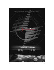
<strong>Power</strong> Side<br />
1. POWER<br />
A red light indicates that the amplifiier is turned on (After warm-up sequence).<br />
2. WARM UP<br />
A red light indicated that the tubes are warming up. (Refer to Pg. 4; Remote Turn-on)<br />
3. POWER / GROUND<br />
After you have securely connected your power and ground wires, plug in the<br />
connector here.<br />
HANDCRAFTED IN THE USA<br />
By <strong>Precision</strong> <strong>Power</strong><br />
P O W E R C O N N E C T<br />
P O W E R<br />
WA R M U P<br />
1 2 3<br />
9<br />
BACK TO <strong>CONTENTS</strong>
Input/Control Side<br />
1. SPEAKER OUTPUTS/REMOTE(Turn on)<br />
After connecting remote and speaker wires plug in the connector here.<br />
2. GAIN CONTROL<br />
Use this control to match the output level of the head unit to the outputs of the amplifier<br />
3. BALANCED INPUT<br />
Plug in the mini-din output from the LDX-33 crossover, LD-3 line driver, or other<br />
balanced source here.<br />
4. -12dB<br />
For use with high level inputs (4V up to 12V). Push this switch in to attenuate the<br />
input by 12dB.<br />
1 2 3 4 5 6<br />
HANDCRAFTED IN THE USA<br />
By <strong>Precision</strong> <strong>Power</strong><br />
SPEAKER OUTPUTS<br />
L- L+ REM R+ R-<br />
GAIN<br />
BALANCED<br />
INPUT<br />
DIN/RCA<br />
-12dB<br />
L<br />
INPUTS<br />
R<br />
7<br />
5. BALANCED / RCA<br />
This switch is used to select between the unbalanced RCA inputs or the balanced<br />
MINI-DIN inputs.<br />
6. INPUTS<br />
Plug in the RCA outputs from your head unit here.<br />
7. COOLING VENTS<br />
10<br />
BACK TO <strong>CONTENTS</strong>
No Sound<br />
Is the WARM UP LED illuminated?<br />
YES<br />
The warm up cycle can take up to<br />
40 sec., Is there sound after that?<br />
NO<br />
Do you have 12V at the amplifier’s<br />
connections?<br />
NO<br />
YES<br />
YES<br />
NO<br />
Is there<br />
signal on the<br />
RCA’s?<br />
YES<br />
Contact your<br />
dealer<br />
You’re done<br />
Does the amp<br />
remote (REM)<br />
have 12V?<br />
YES<br />
Check main<br />
system fuse.<br />
Did that work?<br />
NO<br />
Check all<br />
connections.<br />
Repair as<br />
needed<br />
Trace back the amp<br />
remote to your source<br />
unit. Repair as needed<br />
YES<br />
You’re done<br />
NO<br />
Contact your<br />
dealer<br />
Amplifier Turning Down at Normal Volume<br />
Turn the system off, wait approx. 5 min., then turn<br />
the system back on. Listen for awhile. Did it work?<br />
NO<br />
YES<br />
Check speaker wires for shorts or other<br />
damage and correct as needed.<br />
Did that fix the problem?<br />
YES<br />
You’re done<br />
NO<br />
If sound is heard, the Amp may have<br />
thermally turned down. Check for proper<br />
air flow and correct as needed. You’re<br />
done.<br />
Check voltage supply to<br />
ensure sufficient voltage.<br />
Did that work?<br />
YES<br />
NO<br />
You’re done<br />
Contact your<br />
dealer<br />
11<br />
BACK TO <strong>CONTENTS</strong>
No Sound in One Channel<br />
Check the pre-amp (RCA/Mini-Din) cables for open connections and make<br />
corrections. Did you find open connections?<br />
NO<br />
Reverse the left and right inputs.<br />
YES<br />
You’re done<br />
SOUND IS NOW IN...<br />
Opposite Channel<br />
Same Channel<br />
Problem is further up the signal path.<br />
Reconnect RCA’s to amp as normal.<br />
Reverse RCA inputs at crossover.<br />
Opposite Channel<br />
Reverse RCA outouts of head unit<br />
Opposite Channel<br />
Problem is in the head unit<br />
Problem is in the speaker or speaker<br />
wire of the silent channel. Check<br />
speaker leads for pinched, shorted, or<br />
open connections.<br />
Amplifier Turning Down at High Volume<br />
Check speaker cables for shorts. Check for<br />
excessively low speaker impedance. Fixed?<br />
NO<br />
YES<br />
Check voltage supply to ensure sufficient voltage is You’re done<br />
being delivered. Is amp getting enough air to cool<br />
off? Did that solve the problem?<br />
NO<br />
YES<br />
If using passive crossovers, are the You’re done<br />
connections correct?<br />
NO<br />
Voltage at amp may be<br />
dropping below minimum<br />
limits.<br />
SOUND IS NOW IN...<br />
SOUND IS NOW IN...<br />
YES<br />
Same Channel<br />
Problem is in the crossover. Contact<br />
your dealer.<br />
Same Channel<br />
Problem is in the RCA cables.<br />
<strong>Power</strong> output of amp may exceed<br />
power handling of parts. Upgrade as<br />
needed.<br />
12<br />
BACK TO <strong>CONTENTS</strong>
Noises While the Engine is On<br />
Alternator whine:<br />
This noise changes in frequency with engine RPM. Check for:<br />
. Excessive input level<br />
. High resistance in cabling or corroded and/or loose connections<br />
. Polarity of the input cables<br />
If the problem persists, check the whines and pops checklist below.<br />
Ticks/buzz:<br />
This noise should go faster and slower with engine RPM, but not really change in<br />
frequency. This is due to the ignition or the fuel pump.<br />
. Try moving the input cables to avoid contact with the fuel pump or wiring<br />
If the problem persists, check the whines and pops checklist below.<br />
Accessory pop:<br />
This popping noise occurs as the result of turn signals, brake lights, etc. You can<br />
try:<br />
. Moving the cables to avoid contact with the wires for the accessories<br />
. Relocating various ground connections<br />
Whines and pops:<br />
If you have a combination of noises, or if one or more of the problems listed above<br />
persists despite efforts to stop the problem, the noise may be caused by one or<br />
more of the following problems:<br />
. Excessively high input level setting on the amplifier<br />
. Poor or open shielding, extra long cables or corroded input cables<br />
. Bad connections<br />
. Bad (or high resistance) system ground<br />
. Reversed polarity on audio signal cables<br />
. Poor quality source unit<br />
13<br />
BACK TO <strong>CONTENTS</strong>
Noises While the Engine is On or Off<br />
System hiss:<br />
System hiss is a white noise that occurs even when the engine is off. It is<br />
usually due to excessively high gain settings. If the hiss is still audible<br />
when you disconnect the input cables from the amplifier, check the input<br />
level on the amplifier. If the hiss disappears when you remove the input<br />
cable, it may be a poor quality source unit, components between the<br />
amplifier and the source unit, or poor level settings.<br />
Distortion:<br />
Distortion is garbled sounding music. This can often be caused by a shorted<br />
speaker wire. Symptoms of this include no sound in one channel and severe<br />
distortion in the other. Use the following guide to help you find the source of<br />
distortion.<br />
Is there audible distortion at all of<br />
the amplifier outputs?<br />
NO<br />
Check each side of the amplifier<br />
independently to see if the<br />
distortion is only on one channel.<br />
Is that the case?<br />
YES<br />
Try reducing the input level<br />
controls.<br />
NO<br />
Check for distortion in<br />
the signal path prior to<br />
the amplifier.<br />
YES<br />
Swap the output connection left to<br />
right. Check for shorted speaker wire.<br />
Did the problem switch sides?<br />
NO<br />
Swap the input side<br />
left/right. Did the<br />
distortion switch<br />
sides?<br />
YES<br />
Check and/or replace<br />
the speaker that is<br />
distorting.<br />
NO<br />
Contact your dealer.<br />
YES<br />
Check the source unit and<br />
components between the source<br />
unit and amplifier<br />
14<br />
BACK TO <strong>CONTENTS</strong>
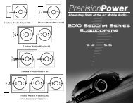
FN-3<br />
2 w a y C r o s s o v e r<br />
INPUT WOOFER TWEETER<br />
+ - + - 0dB -2dB -<br />
TD<br />
225A<br />
FN-3<br />
2 w a y C r o s s o v e r<br />
INPUT WOOFER TWEETER<br />
+ - + - 0dB -2dB -<br />
FN-6<br />
IN<br />
Woofer Midrange Tweeter<br />
-2dB 0 dB -2dB 0 dB<br />
+ - - + - - + - - +<br />
TD<br />
225A<br />
2200<br />
eject<br />
VOLUME<br />
eject<br />
VOLUME<br />
BASS<br />
BASS<br />
TREBLE<br />
BALANCE<br />
LEFT<br />
RIGHT<br />
TREBLE<br />
BALANCE<br />
LEFT<br />
RIGHT<br />
1 2 3 4<br />
5<br />
6<br />
7<br />
8<br />
TRACK<br />
FOWARD REVERSE<br />
1 2 3 4<br />
5<br />
6<br />
7<br />
8<br />
TRACK<br />
FOWARD REVERSE<br />
PPI MAR KET ING DPT<br />
PPI MAR KET ING DPT<br />
TD<br />
2200<br />
FN-6<br />
IN<br />
Woofer Midrange Tweeter<br />
-2dB 0 dB -2dB 0 dB<br />
+ - - + - - + - - +<br />
Source Unit<br />
Trk 1<br />
LD4<br />
LD3<br />
Studio Driver<br />
System 6<br />
FN6<br />
Highpass<br />
filter<br />
Highpass<br />
filter<br />
FN6<br />
Studio Driver<br />
System 6<br />
TD<br />
TD2200 PRO<br />
Lowpass filter<br />
Subwoofer<br />
Source Unit<br />
Trk 1<br />
LD3<br />
LDX33<br />
Highpass<br />
Lowpass<br />
MidBass<br />
TD225A<br />
TD2200<br />
TD 225A TD<br />
2200<br />
TD225A<br />
Studio Driver<br />
System 1<br />
StudioDriver<br />
MW64<br />
Subwoofers<br />
15<br />
BACK TO <strong>CONTENTS</strong>
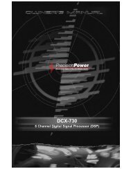
RCA<br />
Right Input<br />
DIF.<br />
AMP<br />
INPUT ATTENUATION<br />
RCA<br />
Left Input<br />
MINI-DIN<br />
Input<br />
Left<br />
Right<br />
BALANCED/RCA<br />
Switch<br />
BALANCED/RCA<br />
Switch<br />
DIF.<br />
GAIN<br />
GAIN<br />
AMP<br />
Left<br />
Right<br />
16<br />
BACK TO <strong>CONTENTS</strong>
Three-Year Limited U.S.A. Warranty<br />
This warranty gives you specific legal rights, and you may also have other rights which vary from<br />
state to state. TUBE DRIVER warrants its products to be free from defects in materials and<br />
workmanship under normal use and service for a period of three (3) years from the date of<br />
original purchase when the unit is installed by an Authorized Dealer. Non-Authorized Dealer<br />
installed products carry a one (1) year parts and ninety (90) days labor limited warranty. The<br />
extent and conditions of Limited Warranty are as follows:<br />
1. Authorized Dealer Installed Products: TUBE DRIVER will either repair or replace at no charge,<br />
to the original purchaser, any unit which upon examination discloses to be defective and under<br />
warranty, provided the defect occurs within three (3) years from the date of original purchase<br />
when the unit is installed by an Authorized Dealer and the product is returned immediately to<br />
TUBE DRIVER. This warranty is not transferable.<br />
2. Non-Authorized Dealer Installed Products: TUBE DRIVER will either repair or replace at no<br />
charge, to the original purchaser, any unit which upon examination discloses to be defective and<br />
under warranty, provided the defect occurs within ninety (90) days from the date of purchase and<br />
the product is returned immediately to TUBE DRIVER. Warranty claims beyond ninety (90) days<br />
for Non-Authorized Dealer Installed Products will be for parts only and will extend for one (1)<br />
year from the date of purchase. This warranty is not transferable.<br />
3. The date of purchase and proof of Authorized Dealer Installation of a TUBE DRIVER product<br />
must be established by an original sales receipt which must accompany the article being returned<br />
for warranty work.<br />
4. This warranty shall NOT apply to any TUBE DRIVER product found to have the original factory<br />
serial number removed or defaced. All products received (by TUBE DRIVER) for in warranty or<br />
out of warranty repair, with their original serial numbers removed or defaced, will NOT be repaired<br />
and will be returned to sender, freight collect. Refer to original packaging for the serial number of<br />
your component speakers.<br />
5. The provisions of this warranty shall not apply to any TUBE DRIVER product used for a purpose<br />
for which it is not designed, which has been repaired or altered in any way, or which has been<br />
connected, installed, or adjusted other than in accordance with the instructions furnished in TUBE<br />
DRIVER’S owner’s manual. Nor shall this warranty apply to any part which has been subject to<br />
misuse, neglect, or accident.<br />
6. TUBE DRIVER does not authorize any other persons to assume any other liability in connection<br />
with its products. THIS WARRANTY IS THE ONLY EXPRESS WARRANTY MADE BY<br />
TUBEDRIVER APPLICABLE TO ITS PRODUCTS. ANY IMPLIED WARRANTY OR<br />
MERCHANTABILITY OR FITNESS FOR A PARTICULAR PURPOSE APPLICABLE TO<br />
TUBEDRIVER PRODUCTS IS LIMITED IN DURATION TO THE DURATION OF THIS LIMITED<br />
WARRANTY. TUBEDRIVER SHALL NOT BE LIABLE FOR THE INCIDENTAL,<br />
CONSEQUENTIAL, OR COMMERCIAL DAMAGES RESULTING FROM THE BREACH OF THIS<br />
WRITTEN WARRANTY. Some states or provinces do not allow the exclusion or limitation of<br />
incidental or consequential damages or limitations on how long an implied warranty lasts; so the<br />
above limitations or exclusions may not apply to you.<br />
7. Your product will be serviced on an in-warranty basis within the warranty period for the correction<br />
of warranted defects. If improper operation of your TUBE DRIVER product should occur, contact<br />
your Authorized Dealer for assistance with the return and factory repair of your TUBEDRIVER<br />
product. If an Authorized Dealer is not available, return the unit including your name, telephone<br />
number, return address, a copy of your sales receipt, and a description of the problem to:<br />
TUBE DRIVER, Inc.<br />
Service Department<br />
4829 S. 38th Street<br />
Phoenix, AZ 85040-2964<br />
TO RETURN TUBEDRIVER PRODUCTS OUT OF WARRANTY: Return the unit, postage prepaid,<br />
in the original protective carton. Please include a description of the problem and, if desired, a<br />
request for an estimate of repair costs. Unless a request for an estimate is included, the unit will<br />
be repaired as necessary. Please contact TUBE DRIVER Customer Service at 1-888-627-6937<br />
for questions concerning out of warranty repair charges. Repaired unit will be returned with an<br />
itemized statement, C.O.D.<br />
BACK TO <strong>CONTENTS</strong>