1.20 CYLINDER LINER - ddcsn
1.20 CYLINDER LINER - ddcsn
1.20 CYLINDER LINER - ddcsn

You also want an ePaper? Increase the reach of your titles
YUMPU automatically turns print PDFs into web optimized ePapers that Google loves.
SERIES 60 SERVICE MANUAL<br />
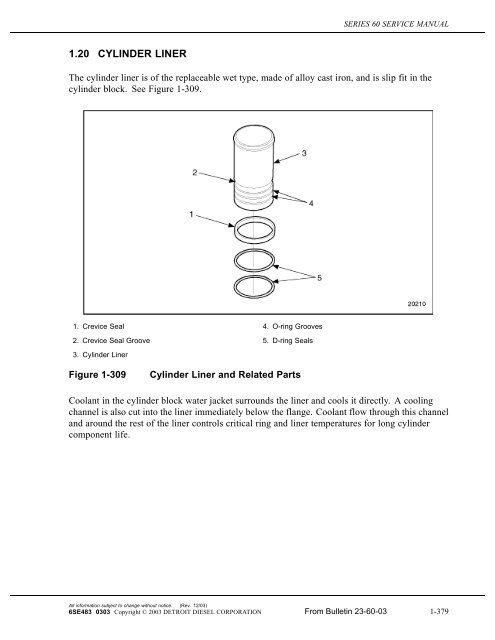
<strong>1.20</strong> <strong>CYLINDER</strong> <strong>LINER</strong><br />
The cylinder liner is of the replaceable wet type, made of alloy cast iron, and is slip fit in the<br />
cylinder block. See Figure 1-309.<br />
1. Crevice Seal 4. O-ring Grooves<br />
2. Crevice Seal Groove 5. D-ring Seals<br />
3. Cylinder Liner<br />
Figure 1-309<br />
Cylinder Liner and Related Parts<br />
Coolant in the cylinder block water jacket surrounds the liner and cools it directly. A cooling<br />
channel is also cut into the liner immediately below the flange. Coolant flow through this channel<br />
and around the rest of the liner controls critical ring and liner temperatures for long cylinder<br />
component life.<br />
All information subject to change without notice. (Rev. 12/03)<br />
6SE483 0303 Copyright © 2003 DETROIT DIESEL CORPORATION From Bulletin 23-60-03 1-379
<strong>1.20</strong> <strong>CYLINDER</strong> <strong>LINER</strong><br />
The liner is inserted in the cylinder bore from the top of the cylinder block. The flange at the top<br />
of the liner fits into a counter bore in the cylinder block. See Figure 1-310.<br />
Figure 1-310<br />
Cylinder Liner to Block Positioning<br />
NOTE:<br />
The cylinder liner, piston and connecting rod must be installed as a assembly in 14L<br />
engines and 12.7L EGR On-Highway engines. Refer to section 1.18.<br />
(Rev. 12/03)<br />
All information subject to change without notice.<br />
1-380 From Bulletin 23-60-03 6SE483 0303 Copyright © 2003 DETROIT DIESEL CORPORATION
SERIES 60 SERVICE MANUAL<br />
NOTICE:<br />
The crevice seal prevents coolant from being pumped in and out<br />
of the area adjacent to the liner lower block location which could<br />
result in cavitation and corrosion damage to the liner and the<br />
block.<br />
A crevice seal, fitting in the wide uppermost groove in the liner helps to stabilize the liner in the<br />
cylinder block bore. This system also keeps any debris that is in the cooling system from causing<br />
abrasion damage to the upper "D" liner seal ring. See Figure 1-311.<br />
Figure 1-311<br />
Cylinder Liner Crevice Seal Cross-Section<br />
All information subject to change without notice. (Rev. 12/03)<br />
6SE483 0303 Copyright © 2003 DETROIT DIESEL CORPORATION From Bulletin 23-60-03 1-381
<strong>1.20</strong> <strong>CYLINDER</strong> <strong>LINER</strong><br />
Two teflon-coated, D-shaped seal rings, recessed in the lower two grooves in the cylinder liner,<br />
are used between the liner and the block to prevent coolant and oil leakage. See Figure 1-312.<br />
Figure 1-312<br />
Cylinder Liner Seal Ring Cross-section<br />
(Rev. 12/03)<br />
All information subject to change without notice.<br />
1-382 From Bulletin 23-60-03 6SE483 0303 Copyright © 2003 DETROIT DIESEL CORPORATION
SERIES 60 SERVICE MANUAL<br />
A weep hole for each cylinder is drilled through the cylinder block exterior, into the cylinder bore<br />
area. This weep hole is located between the two D-shaped seal rings. It is used to determine if<br />
engine coolant is leaking past the upper liner seal, or if oil is leaking past the lower liner seal.<br />
See Figure 1-313. A special rubber plug prevents dirt from getting into the "D" seal ring areas<br />
and causing abrasive damage. At the same time it allows leaking oil or coolant a path out of the<br />
engine for detection.<br />
Figure 1-313<br />
Weep Hole Plug Locations<br />
All information subject to change without notice. (Rev. 12/03)<br />
6SE483 0303 Copyright © 2003 DETROIT DIESEL CORPORATION From Bulletin 23-60-03 1-383
<strong>1.20</strong> <strong>CYLINDER</strong> <strong>LINER</strong><br />
<strong>1.20</strong>.1 Repair or Replacement of Cylinder Liner<br />
To determine if repair is possible or replacement is necessary, perform the following procedure.<br />
SeeFigure1-314.<br />
Figure 1-314<br />
Flowchart for Repair or Replacement of Cylinder Liner<br />
(Rev. 12/03)<br />
All information subject to change without notice.<br />
1-384 From Bulletin 23-60-03 6SE483 0303 Copyright © 2003 DETROIT DIESEL CORPORATION
SERIES 60 SERVICE MANUAL<br />
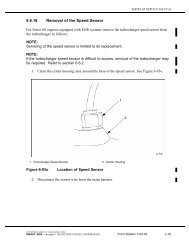
<strong>1.20</strong>.2 Removal and Cleaning of Cylinder Liner<br />
Precleaning is not necessary.<br />
NOTICE:<br />
Refer to section 1.18.2 for removal of 14L and 12.7L EGR<br />
ON-Highway Cylinder Liner, Piston and Connecting Rod<br />
assembly.<br />
NOTICE:<br />
The proper method must be followed when removing a cylinder<br />
liner. Damage to the liner and the cylinder block may occur if the<br />
proper tools and procedures are not used.<br />
1. Remove the piston and connecting rod as an assembly. Refer to section 1.18.2.<br />
All information subject to change without notice. (Rev. 12/03)<br />
6SE483 0303 Copyright © 2003 DETROIT DIESEL CORPORATION From Bulletin 23-60-03 1-385
<strong>1.20</strong> <strong>CYLINDER</strong> <strong>LINER</strong><br />
2. Remove the cylinder liner with cylinder liner remover, J 45876 . See Figure 1-315.<br />
Figure 1-315 Cylinder Liner Removal Tool J 45876<br />
[a]<br />
[b]<br />
Ease the liner removal tool down into the liner.<br />
Turn the nut on tool J 45876 in a clockwise direction to remove liner from the block.<br />
NOTE:<br />
After removing liners from an engine and prior to installing liners, always store them in<br />
an upright position until ready for use. Liners left on their side for any length of time<br />
can become egg-shaped and distorted, making installation in cylinder bores difficult or<br />
impossible. If the cylinder liners are to be reused, they should be marked for cylinder<br />
locationandengineorientation,apaintmarkcanbeusedtoindicatethefrontofengine<br />
so they may be installed to the same cylinder from which they were removed.<br />
[c]<br />
Remove the tool from the liner.<br />
(Rev. 12/03)<br />
All information subject to change without notice.<br />
1-386 From Bulletin 23-60-03 6SE483 0303 Copyright © 2003 DETROIT DIESEL CORPORATION
SERIES 60 SERVICE MANUAL<br />
[d]<br />
Remove the seals (all three) from the liner and discard them.<br />
<strong>1.20</strong>.2.1 Cleaning of the Cylinder Liner<br />
Clean the cylinder liner prior to inspection as follows:<br />
1. If cleaning a new or used liner, wash the liner with a strong detergent and warm water<br />
solution, scrubbing with a non-metallic bristle brush.<br />
2. Rinse with hot water or steam.<br />
To avoid injury from flying debris when using compressed<br />
air, wear adequate eye protection (face shield or safety<br />
goggles) and do not exceed 40 psi (276 kPa) air pressure.<br />
3. Dry the liner with compressed air.<br />
NOTICE:<br />
If the liners are not to be installed at this time, oil them lightly with<br />
clean engine lubricating oil and store them upright in a clean, dry<br />
area. Do not allow the liners to rest on their sides and do not<br />
storeanythingontopoftheliners.<br />
4. Coat the bore of the liner with clean engine lubricating oil.<br />
5. Allow the liner to sit for 10 minutes (to allow the oil to work into the surface finish).<br />
6. Wipe the inside of the liner with clean, white paper towels.<br />
7. If a dark residue appears on the towels, repeat the oiling and wiping procedure until<br />
residue no longer appears.<br />
<strong>1.20</strong>.2.2 Inspection of Cylinder Liner<br />
Inspect the cylinder liner as follows:<br />
1. Inspect the cylinder liner.<br />
[a] Check the cylinder liner for cracks or scoring.<br />
[b] If any of these are detected, replace with a new part.<br />
All information subject to change without notice. (Rev. 12/03)<br />
6SE483 0303 Copyright © 2003 DETROIT DIESEL CORPORATION From Bulletin 23-60-03 1-387
<strong>1.20</strong> <strong>CYLINDER</strong> <strong>LINER</strong><br />
NOTICE:<br />
Erosion is due to poor cooling system maintenance. If<br />
uncorrected, it will eventually make holes through the liner. This<br />
can result in combustion gases blowing water out of the radiator,<br />
oil in the coolant, or when the engine is stopped will allow water<br />
to flow into the cylinder and result in major engine damage due<br />
to water in the oil or hydraulic lockup.<br />
[c] Check the cylinder liner for cavitation erosion. See Figure 1-316.<br />
1. Cracks 3. Erosion<br />
2. Cylinder Liner<br />
Figure 1-316<br />
Cylinder Liner Cavitation Erosion<br />
[d] If cavitation erosion occurs, replace with a new part. Refer to section <strong>1.20</strong>.3.<br />
NOTICE:<br />
Series 60 cylinder liners are honed at the factory with a process<br />
that cannot be duplicated in the field. For this reason, honing of<br />
used liners should not be attempted.<br />
2. Inspect the outside diameter of the liner.<br />
[a] Check liner for fretting.<br />
[b] If any fretting is found, remove it from the surface of the liner with a coarse, flat stone.<br />
(Rev. 12/03)<br />
All information subject to change without notice.<br />
1-388 From Bulletin 23-60-03 6SE483 0303 Copyright © 2003 DETROIT DIESEL CORPORATION
SERIES 60 SERVICE MANUAL<br />
3. Inspect the liner flange.<br />
[a] Check the liner flange for cracks, smoothness and flatness on both the top and<br />
bottom surfaces.<br />
[b] If these are detected, replace with a new part.<br />
4. Inspect the block bore and cylinder liner.<br />
[a] Measure the block bore and the outside diameter of the liner. The liner specifications<br />
are listed in Table 1-16. The block specifications are listed in Table 1-15.<br />
Refer to section 1.1.3.3 for procedures.<br />
[b] If the liner does not meet specification, replace with a new part.<br />
All information subject to change without notice. (Rev. 12/03)<br />
6SE483 0303 Copyright © 2003 DETROIT DIESEL CORPORATION From Bulletin 23-60-03 1-389
<strong>1.20</strong> <strong>CYLINDER</strong> <strong>LINER</strong><br />
5. Inspect inside diameter of cylinder liners.<br />
[a] Set the cylinder bore gage on zero in master setting fixture. Use cylinder bore gage,<br />
J 5347-B, to measure the inside diameter of the liner of various points. The maximum<br />
diameter of a used liner is 130.100 mm (5.122 in.) for 12.7 and 11.1 L and 133.100<br />
mm (5.244 in.) for 14L at any measurement location. See Figure 1-317. Also check<br />
the liner for taper and out-of-round.<br />
Figure 1-317<br />
Cylinder Liner Measurement Diagram<br />
[b] If the taper and out-of-round exceed 0.025 mm (0.001 in.), replace with a new part.<br />
6. Inspect the cylinder liner.<br />
[a] Check the seal ring and crevice seal grooves for burrs or sharp edges.<br />
[b] If any are detected, smooth with an emery cloth.<br />
(Rev. 12/03)<br />
All information subject to change without notice.<br />
1-390 From Bulletin 23-60-03 6SE483 0303 Copyright © 2003 DETROIT DIESEL CORPORATION
SERIES 60 SERVICE MANUAL<br />
<strong>1.20</strong>.3 Installation of Cylinder Liner<br />
Install the cylinder liner as follows:<br />
NOTE:<br />
Refer to section 1.18 for 14L and 12.7L EGR On-Highway liner, piston and connecting<br />
rod procedure.<br />
1. Wipe the inside and outside of the liner clean. Be sure the block bore and counter bore<br />
are clean, so the liner flange will seat properly. The block counter bore depth must be<br />
8.9255-8.9662 mm (0.3514 -0.3530 in.) and must not vary more than 0.04 mm (0.0016<br />
in.) in depth around the circumference. No two adjacent block counter bores may range in<br />
depth more than 0.025 mm (0.001 in.) when gaged along the longitudinal cylinder block<br />
centerline. Specifications are listed in Table 1-15, and listed in Table 1-16.<br />
NOTE:<br />
Thoroughly clean the cylinder block liner counter bores to remove any foreign material.<br />
Foreign material in the cylinder liner counter bores can cause the liner to seat improperly.<br />
2. Lubricate the seal rings and crevice seal with clean petroleum jelly.<br />
3. Install two new seal rings and a new crevice seal into their respective grooves in the liner.<br />
4. Insert the cylinder liner into the cylinder bore.<br />
NOTE:<br />
Do not exert excessive force on the liner, while pushing it down.<br />
All information subject to change without notice. (Rev. 12/03)<br />
6SE483 0303 Copyright © 2003 DETROIT DIESEL CORPORATION From Bulletin 23-60-03 1-391
<strong>1.20</strong> <strong>CYLINDER</strong> <strong>LINER</strong><br />
5. Install J 35597-A, over the liner to be installed. See Figure 1-318.<br />
NOTE:<br />
It is necessary to leave the cylinder liner installation tool in place until after the liner<br />
protrusion is measured.<br />
Figure 1-318<br />
Cylinder Liner Instalation Tools<br />
6. Thread three cylinder head bolts through the tool and into a head bolt hole, so that the<br />
round shoe of the tool is centered over the liner.<br />
7. Tighten the bolts.<br />
NOTE:<br />
It is not necessary to torque the bolts.<br />
8. Turn the threaded center bolt in a clockwise direction. As the round shoe of the tool<br />
reaches the liner, ensure that the shoe is properly positioned into the cylinder liner.<br />
9. Continue turning the bolt until the liner bottoms in the cylinder counterbore. Apply a<br />
tightening torque of 60 N·m (44 lb·ft) to the installation tool center bolt.<br />
10. Install a dial indicator sled gage. See Figure 1-298.<br />
(Rev. 12/03)<br />
All information subject to change without notice.<br />
1-392 From Bulletin 23-60-03 6SE483 0303 Copyright © 2003 DETROIT DIESEL CORPORATION
SERIES 60 SERVICE MANUAL<br />
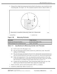
11. Measure the distance from the top of the liner flange to the top of the block.<br />
See Figure 1-319.<br />
[a] Allowable liner protrusion is -0.0127-0.0762 mm (-0.0005-0.003 in.) with no<br />
more than 0.0508 mm (0.002 in.) variation between any two adjacent cylinders.<br />
Specifications are listed in Table 1-16.<br />
[b] If the liner protrusion exceeds the maximum allowable, remove the liner and check<br />
for debris under the liner flange.<br />
Figure 1-319<br />
Cylinder Liner Protrusion<br />
12. Remove the cylinder liner tool.<br />
13. With all of the cylinder liners installed and the liner protrusion measurements within<br />
specifications, install the piston and connecting rod assemblies. Refer to section 1.18.5.<br />
All information subject to change without notice. (Rev. 12/03)<br />
6SE483 0303 Copyright © 2003 DETROIT DIESEL CORPORATION From Bulletin 23-60-03 1-392a
<strong>1.20</strong> <strong>CYLINDER</strong> <strong>LINER</strong><br />
This page intentionally left blank.<br />
(Rev. 12/03)<br />
All information subject to change without notice.<br />
1-392b From Bulletin 23-60-03 6SE483 0303 Copyright © 2003 DETROIT DIESEL CORPORATION