Installation Manual - GSI Highway Products
Installation Manual - GSI Highway Products
Installation Manual - GSI Highway Products

Create successful ePaper yourself
Turn your PDF publications into a flip-book with our unique Google optimized e-Paper software.
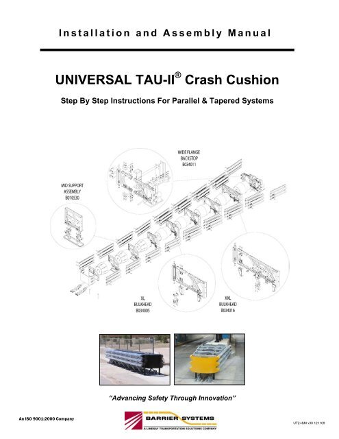
<strong>Installation</strong> and Assembly <strong>Manual</strong><br />
UNIVERSAL TAU-II TAU-II ® Crash Crash Cushion Cushion<br />
Step By Step Instructions For Parallel & Tapered Systems<br />
Step By Step Instructions For Parallel & Tapered Systems<br />
Patents Pending<br />
Copyright © 2001 BSI<br />
“Advancing Safety Through Innovation”<br />
An ISO 9001:2000 Company<br />
Page 1<br />
UT2-I&M v30 121109
Universal TAU-II ® Crash Cushion INTRODUCTION<br />
This page left blank<br />
Page 2
Universal TAU-II ® Crash Cushion INTRODUCTION<br />
TABLE OF CONTENTS<br />
Preface ………………………..…………… 4<br />
Introduction ………………………………… 4<br />
System Overview ……….………………… 4<br />
Required Tools ………..…………………. 4<br />
Before <strong>Installation</strong> ………………………… 5<br />
Limitations and Warnings………………… 5<br />
Parts Index ………………….………….. 6<br />
PARALLEL SYSTEM INSTALLATION<br />
Preparing for installation …………………. 8<br />
Step 1. Backstop <strong>Installation</strong> ……………. 10<br />
Step 2. Rear Cable Anchor <strong>Installation</strong> ... 11<br />
Step 3. Front Cable Anchor <strong>Installation</strong> … 12<br />
Step 4. Install Diaphragms ……………….. 13<br />
Step 5. Install Guide Cables ……………. 14<br />
Step 6. Attach Pipe Panel Mounts ……… 15<br />
Step 7. Install Side Panels ……..……….. 16<br />
Step 8. Assemble Nose Assembly …….. 18<br />
Step 9. Install Energy Absorbing<br />
Cartridges ………………………… 19<br />
Step 10. Tension Guide Cables …………. 20<br />
Step 11. Final Inspection ………………… 20<br />
TAPERED SYSTEM INSTALLATION<br />
Introduction ………………………………. 21<br />
System Overview ……………………….. 22<br />
Required Tools ………………………….. 22<br />
Step 1. Foundation Requirements ……… 23<br />
Step 2. Anchoring System .……………… 24<br />
Step 3. Assemble Bulkheads .…………… 25<br />
The Front Support ……..… 26<br />
Middle Assembly …... ……. 27<br />
Step 4. Backstop Assemblies …. …..…… 30<br />
Compact Backstop ………. 31<br />
Flush Mount Backstop …… 32<br />
Wide Flange Backstop …… 33<br />
Step 5. Attach Side Panels ………. …….. 35<br />
Step 6. Attach Nose Piece ………………. 36<br />
Step 7. Install Cables / Guides ………….. 37<br />
Step 8. Stretch and Align System …….… 39<br />
Step 9. Tension Cables / Torque<br />
Sliders bolts ………………..……. 39<br />
Step 10. Install Lateral Support Cables ..... 40<br />
Step 11. Insert Energy Absorbing<br />
Cartridges ………………………… 42<br />
Step 12. Final Inspection …………….…… 43<br />
APPENDIX<br />
A. System Configuration Chart …….. 44<br />
B. System Torque Chart ………….... 46<br />
C. System Foundation Drawings….… 47<br />
D. System Transition Drawings ……. 63<br />
E. <strong>Installation</strong> Instructions to BarrierGuard<br />
800 Steel Barrier ………………….. 76<br />
Page 3
Universal TAU-II ® Crash Cushion INTRODUCTION<br />
PREFACE<br />
The Barrier Systems, Inc. (BSI), Universal TAU-II<br />
crash cushion system incorporates the newest<br />
roadside safety materials and engineering processes.<br />
As with any roadside safety device, the Universal<br />
TAU-II system must be installed properly to insure<br />
proper performance. Thoroughly review and fully<br />
understand the installation instructions and product<br />
limitations before starting the installation. Do not start<br />
the installation without the proper plans and tools<br />
required for installation.<br />
If you need additional information, or have<br />
questions about the Universal TAU-II Crash<br />
Cushion, please call the BSI Customer Service<br />
Department at (888) 800-3691 (U.S. toll free) or<br />
(707) 374-6800.<br />
INTRODUCTION<br />
The TAU-II system has been tested to meet the<br />
rigorous requirements of NCHRP Report 350, Test<br />
Levels 2 and 3. The systems will be provided in<br />
lengths and capacities for both low speed and high<br />
speed applications.<br />
The TAU-II system is redirective and non-gating, and<br />
is ideally suited for narrow hazards such as the ends<br />
of rigid barriers, tollbooths, utility poles and more.<br />
Ease of installation, numerous transition options, low<br />
maintenance requirements, and reusability of system<br />
components make the TAU-II system ideal for<br />
treating many roadside hazards.<br />
Redirective, non-gating crash cushions are highway<br />
safety devices whose primary function is to improve<br />
the safety for occupants of errant vehicles that impact<br />
the end of rigid or semi-rigid barriers or fixed roadside<br />
hazards by absorbing the kinetic energy of impact or<br />
by allowing controlled redirection of the vehicle.<br />
These devices are designed to safely decelerate an<br />
errant vehicle to a safe stop or redirect an errant<br />
vehicle away from roadside or median hazards.<br />
These types of systems are typically applied to<br />
locations where head-on and angled impacts are<br />
likely to occur and it is desirable to have the majority<br />
of post impact trajectories on the impact side of the<br />
system.<br />
SYSTEM OVERVIEW<br />
The Universal TAU-II system is designed and<br />
constructed to provide acceptable structural<br />
adequacy, minimal occupant risk and safe vehicle<br />
trajectory as set forth in NCHRP 350 for redirective,<br />
non-gating crash cushions. Refer to Figure 1 to<br />
familiarize yourself with the basic parts and part<br />
names of the system.<br />
The Universal TAU-II system is designed to shield the<br />
ends of median barriers and other fixed objects likely<br />
to be struck head-on, by absorbing and dissipating<br />
the kinetic energy of impacting vehicles. Universal<br />
TAU-II systems utilize disposable Energy Absorbing<br />
Cartridges (EACs) to absorb the kinetic energy of the<br />
impacting vehicle. The EACs are separated by<br />
diaphragms and held in place with a framework of<br />
thrie-beam corrugated steel rail panels that<br />
“telescope” rearward during head-on impacts. As the<br />
vehicle compresses the cushion, it exerts a force on<br />
the first bay containing an EAC. The diaphragms<br />
distribute the impact forces uniformly to all the<br />
remaining cartridges in each bay until the vehicle<br />
eventually stops. The depth of penetration is<br />
dependent upon both the original impact speed and<br />
the mass of the impacting vehicle. Only the Energy<br />
Absorbing Cartridges are expended after most headon<br />
impacts.<br />
When hit at an angle along the side, the system is<br />
restrained laterally by guidance cables that run the<br />
length of the system and attach to the bottoms of the<br />
diaphragms and terminate at the anchors at each end<br />
of the system. The front and rear cable anchors are<br />
attached to the foundation as described in Appendix<br />
A Foundation Requirements.<br />
BEFORE TAU-II INSTALLATION<br />
Placement and use of the TAU-II system should be<br />
accomplished in accordance with the guidelines and<br />
recommendations set forth in the “AASHTO Roadside<br />
Design Guide,” FHWA memoranda and other state<br />
and local standards.<br />
Depending on the application and circumstances at<br />
the job site, installation and assembly of a Test Level<br />
3 system should take a two-person crew less than 3<br />
hours.<br />
The TAU-II is a highly engineered safety device made<br />
up of a relatively small amount of parts. Before<br />
Page 4
Universal TAU-II ® Crash Cushion INTRODUCTION<br />
starting the assembly, become familiar with the basic<br />
elements that make up the TAU-II system. The TAU-<br />
II system components are illustrated separately in<br />
Figure 1 (Pages 6-7).<br />
Limitations and Warnings<br />
The Universal TAU-II system has been rigorously<br />
tested and evaluated per the recommendations in the<br />
NCHRP Report 350 Guidelines for terminals and<br />
crash cushions. The impact conditions<br />
recommended in NCHRP 350 are intended to<br />
address typical in-service collisions.<br />
When properly installed and maintained, the system<br />
is capable of stopping or containing and redirecting<br />
impacting vehicles in a predictable and safe manner<br />
under the NCHRP 350 impact conditions.<br />
Vehicle impacts that vary from the NCHRP 350<br />
impact conditions described for redirective, nongating,<br />
crash cushions may result in significantly<br />
different results than those experienced in testing.<br />
Vehicle impact characteristics different than or in<br />
excess of those encountered in NCHRP 350 testing<br />
(speed and angle) may result in system performance<br />
that may not meet the NCHRP 350 evaluation<br />
criteria.<br />
If you need additional information, or have<br />
questions about the Universal TAU-II Crash<br />
Cushion, please call the BSI Customer Service<br />
Department at (888) 800-3691 (U.S. toll free) or<br />
(707) 374-6800.<br />
PROVIDED TOOLS<br />
<br />
<br />
<br />
Long bolt for nested slider panel installation<br />
Allen socket for the slider bolt assembly<br />
Cable socket<br />
REQUIRED TOOLS<br />
<br />
<br />
<br />
<br />
<br />
<br />
<br />
<br />
<br />
<br />
½” [12 mm] drive deep sockets:<br />
3/4” [19 mm], 13/16”, [20 mm],<br />
15/16”, [24 mm], 1 1/8” [30 mm]<br />
3/4” [20 mm] deep socket<br />
3/4” [19mm] combination end wrench<br />
½” (12 mm) drive ratchet with extensions<br />
Rotohammer for drilling holes in concrete:<br />
7/8” [22 mm] X 10” [250 mm] bit for chemical<br />
anchors<br />
½” Torque wrenchs:<br />
20 ft-lbs [27 N-m] and 500 ft-lbs [680 N-m]<br />
capacity<br />
Measuring tape<br />
Safety Equipment: Glasses, Gloves<br />
½” (12 mm) Air impact wrench (Optional)<br />
Note: The tools list is a general recommendation.<br />
Depending on the specific characteristics of the<br />
job site, more or less tools may be necessary.<br />
Page 5
Universal TAU-II ® Crash Cushion INTRODUCTION<br />
B040216<br />
B040214<br />
Flush Mount<br />
Backstop<br />
Wide Flange<br />
Backstop<br />
Pt# B030668<br />
Nose Piece – (wide)<br />
Pt# K001034 Y (Black)<br />
with rivet Kit<br />
Energy Absorbing<br />
Cartridge - Type B<br />
Pt# B010722<br />
Energy Absorbing<br />
Cartridge - Type A<br />
Pt# B010802<br />
Nose Piece Only<br />
(Parallel)<br />
Pt# B030516 (Black)<br />
Compact Backstop<br />
Pt# B040430<br />
Hardware Kit<br />
Pt# K001013<br />
Wide Cable<br />
Parallel Cable<br />
Flush Mount Wide Flange Compact or PCB<br />
Compact Backstop with Asphalt Support<br />
Front Cable Anchor<br />
(Reverse)<br />
Pt# B040412<br />
Front Cable Anchor,<br />
Universal Cable<br />
Pt# B030935<br />
Front Cable Anchor,<br />
Compact Cable<br />
Pt# B010248<br />
B020424<br />
B020423<br />
PCB Backstop<br />
Pt# B040425<br />
Rear Cable Anchor,<br />
(Independent)<br />
Pt# B030938<br />
Rear Cable Anchor<br />
(Backstop Mount)<br />
Pt# B031020<br />
Front Cable Anchor<br />
Asphalt Anchor<br />
Pt# B020425<br />
Cable Key Front<br />
Pt# B040501<br />
PCB Backstop with Cable Anchor and<br />
Barrier Support<br />
Sliding Panel<br />
Pt# B010202<br />
End Panel<br />
Pt# B010659<br />
Angled End Panel<br />
Pt# B040203<br />
Cable Key<br />
Pt# B030942<br />
Figure 1. Illustrated parts list<br />
Page 6
Universal TAU-II ® Crash Cushion INTRODUCTION<br />
XL Bulkhead<br />
Pt# B030521<br />
XXL Bulkhead<br />
Pt# B030528<br />
XXXL Bulkhead<br />
Pt# B030529<br />
Middle Support<br />
Pt# B030703<br />
Front Support<br />
Pt# B030704<br />
Leg Kit Pt# K001005<br />
Wing Assembly<br />
Pt# B030509<br />
Transition Wing Assy.<br />
Pt# B030910<br />
36 Inch Adapter Assy<br />
Pt# B031201<br />
Leg (wide)<br />
Pt# B030425<br />
Bumper Assembly<br />
(wide)<br />
Pt# B031035<br />
Pipe Panel Mount<br />
Pt# B010651<br />
Hardware Kit<br />
Pt# K001017<br />
Backstop Blockout<br />
(wide)<br />
Pt# B030713<br />
Front Collision Plate<br />
(wide)<br />
Pt# B030801<br />
Wing Brace<br />
(wide)<br />
Pt# B030821<br />
Spacer - Wing Brace<br />
(wide)<br />
Pt# B030823<br />
Level Spacer<br />
Pt# B030551<br />
EAC Locator Kit (X4)<br />
Pt# K001028<br />
Slider Assembly Kit (x4)<br />
Pt# K001003<br />
Leg Adapter<br />
(wide)<br />
Pt# A040223<br />
Backing Plate<br />
(wide)<br />
Pt# B030543<br />
Lateral support Mount,<br />
(Backstop Mount - wide)<br />
Pt# B031011<br />
Lateral Support<br />
Cable Assembly Kit<br />
Pt# K001031<br />
Bulkhead Mount,<br />
Lateral Support – (wide)<br />
Pt# B031010<br />
Cable Guide Mounting<br />
Plate – (wide)<br />
Pt# B030411<br />
Cable Guide Assembly<br />
Kit (x4)<br />
Pt# K001004<br />
Page 7
Universal TAU-II ® Crash Cushion INTRODUCTION<br />
Left Side<br />
Rear or Back<br />
- Downstream -<br />
Preparing for installation<br />
Depending on the size of the system ordered, the<br />
parts will be shipped on two to five pallets. Assembly<br />
of the TAU-II system is typically done at the worksite.<br />
(If preferred, the system can be assembled “off-site”<br />
and set into position as one piece, with a forklift or<br />
crane.)<br />
Front or Nose<br />
- Upstream -<br />
Right Side<br />
Sign Conventions<br />
The picture of the TAU-II system above is labeled to<br />
show the descriptive terms that will be used<br />
throughout this manual.<br />
Before beginning the assembly of the TAU-II system,<br />
check the packing list to be certain that all of the<br />
system components were included in the shipment.<br />
The TAU-II Crash Cushion system has been<br />
designed to attach to concrete or asphalt foundations.<br />
BSI recommends that at a minimum, the system be<br />
anchored to standard six-inch reinforced 4,000 psi<br />
(28 MPa) Portland Cement Concrete (PCC) pad or<br />
roadway, or 8” (200 mm) AR-4000 Asphalt Concrete.<br />
When installing to concrete, care must be taken when<br />
building the concrete pad to space the rebar so as to<br />
minimize interference with the anchor bolt holes.<br />
(See Appendix “C”, Page 47, for BSI<br />
recommended foundation options and material<br />
specifications.)<br />
NOTE:<br />
It is important to determine the system’s installation<br />
position and angle, to optimize proper function and<br />
transition.<br />
This system is available in two configurations:<br />
Concrete pad in front of hazard<br />
1) The system can be attached directly to the<br />
end of a concrete barrier, utilizing the “PCB<br />
Backstop” (BSI part # B040425) or the “Flush<br />
Mount Backstop” (BSI part # B040219).<br />
2) The second configuration utilizes a “Compact<br />
Backstop” (BSI part # B010537) which is a<br />
free standing back support.<br />
This manual describes the installation procedure for<br />
an 8 bay (Test Level 3) system.<br />
(See the System Configuration Chart in Appendix<br />
“A”, Page 44, for guidelines on choosing a<br />
system length to accommodate different traffic<br />
criteria.)<br />
Wide system on pallets for shipment<br />
Page 8
Universal TAU-II ® Crash Cushion INTRODUCTION<br />
Depending on the installation design, transition<br />
hardware may be necessary. Because each<br />
transition is unique, BSI recommends that the<br />
transition hardware be properly fitted before<br />
anchoring the system. Pre-assemble the transition<br />
hardware before setting the system base plates to<br />
assure the proper spacing between the system and<br />
the object being treated.<br />
(NOTE: See Appendix “D”, Page 63, for some<br />
recommended transition types)<br />
Page 9
Universal TAU-II ® Crash Cushion PARALLEL SYSTEM<br />
CONCRETE PAD INSTALLATION<br />
ASPHALT INSTALLATION<br />
Use the Base Plate of the Compact Backstop as a template<br />
Compact Backstop Base with Asphalt Adapter<br />
Step 1. (Compact Backstop to Concrete<br />
Foundation)<br />
Place the Compact Backstop in the desired final<br />
installation position. Use the holes in the base plate<br />
as a template to mark the location of the anchor<br />
points. Remove the backstop and drill the anchor<br />
bolt holes. The holes should be 6” (150 mm) deep<br />
and 7/8” (22 mm) diameter. Install the anchors into<br />
the pad following the instructions included with the<br />
anchor epoxy. When the epoxy is fully cured, install<br />
the nuts and flat washers. Tighten to 120 ft-lbs (160<br />
N-m).<br />
Step 1. (Compact Backstop to Asphalt)<br />
If the unit is being installed on asphalt, the Asphalt<br />
Adapter must be attached to the Compact Backstop.<br />
Use the base as a template to mark the anchor point<br />
locations. All holes should be 15 to 16½” (380 to 420<br />
mm) deep. Use 18” (460 mm) anchors for the<br />
Compact Backstop and the Asphalt Adapter. Install<br />
the anchors into the foundation following the<br />
instructions included with the anchor epoxy. When<br />
the epoxy is fully cured, install the nuts and flat<br />
washers. Tighten to 120 ft-lbs (160 N-m).<br />
PCB Backstop<br />
Use the P.C.B. Backstop as a template to drill the holes<br />
Step 1. (PCB Backstop to Concrete Foundation)<br />
Place the PCB Backstop in the desired final<br />
installation position. Use the holes in the backstop as<br />
a template to mark the location of the anchor points.<br />
The holes should be 6” (150 mm) deep and 7/8” (22<br />
mm) diameter. Use a caulking gun and gun insert<br />
filled with anchoring compound to secure the ¾” x 8<br />
¼” (20 mm x 610 mm) galvanized anchors. Torque<br />
to 120 ft-lbs (160 N-m).<br />
Use the P.C.B. Backstop as a template to drill the holes<br />
Step 1. (PCB Backstop to Asphalt Foundation)<br />
Place the PCB Backstop in the desired final<br />
installation position. Use the holes in the backstop as<br />
a template to mark the location of the anchor points.<br />
The holes should be 6” (150 mm) deep and 7/8” (22<br />
mm) diameter. Use a caulking gun and gun insert<br />
filled with anchoring compound to secure the ¾” x 8<br />
¼” (20 mm x 610 mm) galvanized anchors. Torque<br />
to 120 ft-lbs. (160 N-m)<br />
Page 10
Universal TAU-II ® Crash Cushion PARALLEL SYSTEM<br />
CONCRETE PAD INSTALLATION<br />
Step 2. (Concrete Rear Cable Anchors)<br />
NOTE: IF YOU ARE USING THE COMPACT<br />
BACKSTOP, SKIP TO STEP 3.<br />
P.C.B. Backstop<br />
Cable Anchor Bolts (4)<br />
ASPHALT INSTALLATION<br />
Step 2. (Asphalt Rear Cable Anchors)<br />
NOTE: IF YOU ARE USING THE COMPACT<br />
BACKSTOP, SKIP TO STEP 3.<br />
PCB Backstop<br />
PCB Backstop<br />
Cable Anchor Bolts (4)<br />
Front<br />
Use the Cable Anchor Plate as a template for the bolt holes (Right Side)<br />
Use the holes in the plate as a template to mark the<br />
location of the holes for the anchor studs. (There is<br />
one Cable Anchor for each side of the P.C.B.). The<br />
holes should be drilled 6” (150 mm) deep and 7/8”<br />
(22 mm) in diameter. Install the (all thread) studs into<br />
the PCB following the instructions included with the<br />
anchor epoxy. When the epoxy is fully cured, install<br />
the nuts and flat washers. Tighten to 120 ft-lbs (160<br />
N-m).<br />
P.C.B. Backstop<br />
Cable Anchor Bolts (4)<br />
Use the Anchor Plate as a template for the bolt holes (Right Side)<br />
Refer to the <strong>Installation</strong> Drawings in Appendix “C” to<br />
determine the correct Cable Anchor installation<br />
position. Use the holes in the plate as a template to<br />
mark the location of the holes for the anchor studs.<br />
(There is one Cable Anchor for each side of the<br />
P.C.B.). The holes should be drilled 6” (150 mm)<br />
deep and 7/8” (22 mm) in diameter. Install the (all<br />
thread) studs into the PCB following the instructions<br />
included with the anchor epoxy. When the epoxy is<br />
fully cured, install the nuts and flat washers. Tighten<br />
to 120 ft-lbs (160 N-m)<br />
PCB Asphalt Adapter<br />
Front<br />
Use the Cable Anchor Plate as a template for the bolt holes (Left Side)<br />
NOTE: For proper system performance, the<br />
concrete barrier must be rigidly attached to an<br />
adequate foundation. See Appendix “C” for<br />
Anchor Foundation Options and Page 24 for<br />
anchoring material options..<br />
Attach the PCB Asphalt Adapter.<br />
Attach the PCB Asphalt Adapter. Drill holes 6” (150<br />
mm) deep and 7/8” (22 mm) in diameter in the<br />
concrete barrier. Drill 15 to 16 ½” (380 to 420 mm) in<br />
the foundation and install 18” (460 mm) anchors<br />
following the instructions included with the anchor<br />
epoxy. When the epoxy is fully cured, install the nuts<br />
and flat washers. Tighten to 120 ft-lbs (160 N-m).<br />
Page 11
Universal TAU-II ® Crash Cushion PARALLEL SYSTEM<br />
CONCRETE PAD INSTALLATION<br />
ASPHALT INSTALLATION<br />
Front Anchor Tie Channel<br />
Use the Front Anchor Plate as a template<br />
Step 3. (Concrete Front Cable Anchor)<br />
Place the Front Cable Anchor in the desired final<br />
installation position. Use Appendix C for layout<br />
dimensions. Use the holes in the plate as a template<br />
to mark the location of the anchor points. Remove<br />
the plate and drill the anchor bolt holes to the desired<br />
size and depth. The holes should be 6” (150 mm)<br />
deep and 7/8” (22 mm) diameter.<br />
Front Cable Anchor<br />
Front Anchor<br />
Backup Plate<br />
Step 3. (Asphalt Front Cable Anchor)<br />
The Asphalt Front Cable Anchor is a three piece unit.<br />
Place the Front Cable Anchor and the Front Anchor<br />
Backup Plate in the desired final installation position.<br />
Use the holes in the plates as a template to mark the<br />
location of the anchor points. Remove the plates and<br />
drill the anchor bolt holes to the desired size and<br />
depth. The holes should be 15 to 16 ½” (380 to 420<br />
mm) deep and 7/8” (22 mm) diameter. Install the<br />
cable and clevis pin before installing the Front<br />
Anchor Tie Channel. Install the Front Anchor Tie<br />
Channel on top of the Front Cable Anchor and the<br />
Front Anchor Backup Plate.<br />
Drill the anchor bolt holes to the proper size and depth<br />
NOTE:<br />
It is important that the holes are drilled straight and in<br />
the correct position so that the plate will fit back over<br />
the bolts after they have been set with anchoring<br />
material. If the total hole depth cannot be reached<br />
due to interference, a “diamond tip” drill or equivalent<br />
should be used to reach the total hole depth.<br />
Install and torque nuts on the anchor bolts<br />
NOTE:<br />
It is important that the holes are drilled straight and in<br />
the correct position so that the plate will fit back over<br />
the bolts after they have been set with anchoring<br />
material. If the total hole depth cannot be reached<br />
due to rebar interference, a “diamond tip” drill or<br />
equivalent should be used to reach the total hole<br />
depth.<br />
Page 12
Universal TAU-II ® Crash Cushion PARALLEL SYSTEM<br />
ALL FOUNDATIONS<br />
After the anchoring epoxy is properly cured, install a<br />
nut and washer on each of the anchor bolts extending<br />
through the base plates of the Backstop and Front<br />
Cable Anchor plate.<br />
For PC Concrete foundations, torque the nuts to<br />
120 ft-lbs (160 N-m).<br />
For Asphaltic Concrete foundations, torque the<br />
nuts to 5 ft-lbs (8 N-m).<br />
Diaphragms spaced between Backstop and Front Cable Anchor<br />
View of foundation with Diaphragms<br />
The photo above shows what the installation would<br />
look like after the diaphragms have been placed<br />
between the Backstop and the Front Cable Anchor.<br />
Compact Backstop<br />
or P.C.B. Backstop<br />
NOTE: Do not install the Front Support Assembly<br />
and nose piece at this time, it will be installed later.<br />
Front Cable Anchor<br />
Compact Backstop and Front Cable Anchor installed<br />
This photo shows a view of how the installation would<br />
look after the Backstop and Front Cable Anchor are<br />
securely fastened.<br />
Thread the Guide Cable through the Diaphragms<br />
Space Diaphragms between Anchors<br />
Thread through the bottom of each Diaphragm<br />
Step 4.<br />
The Diaphragms should be spaced (one by one)<br />
evenly between the Front Cable Anchor and the<br />
Backstop. It is not important that they be exactly<br />
spaced at this point as they can easily be moved into<br />
the desired final assembly position when necessary.<br />
Step 5.<br />
Starting at the upstream end of the system, thread<br />
the Guide Cable through the space in the bottom of<br />
the Diaphragms. Make sure to pull the threaded<br />
cable end through first so that it will end up at the<br />
back of the unit. (Make sure that the Guide Cable is<br />
threaded through the bottom of each Diaphragm.)<br />
Page 13
Universal TAU-II ® Crash Cushion PARALLEL SYSTEM<br />
P.C.B. Backstop<br />
Compact Backstop<br />
Thread the second cable<br />
Push the threaded end of the cable through the hole<br />
in the anchor tab on the left side of the Compact<br />
Backstop. Install the nut on the end of the adjusting<br />
screw.<br />
NOTE: Do not thread the nut beyond the end of the<br />
adjusting screw at this time. The nut will be tightened<br />
later.<br />
Repeat the process outlined in steps 6, 7, and 8, for<br />
the other cable. Install the second cable along the<br />
right side of the system without crossing the first<br />
cable.<br />
Attach cables to bottom of Diaphragms<br />
Guide Cable to Front Cable Anchor<br />
Pin handle of clevis is on the<br />
inside of the anchor assembly<br />
Attach the other end of the Guide Cable to the left<br />
side of the Front Cable Anchor by first removing the<br />
pin from the clevis (shackle). Place the clevis over<br />
the anchor eye and re-install the pin through the eye,<br />
making sure that the handle portion of the pin is on<br />
the inside of the anchor assembly. Firmly tighten the<br />
pin.<br />
For asphalt installations, the cable and clevis<br />
pin have been attached in Step 3 (Page 12).<br />
Use the Cable Guide Assembly blocks to attach the<br />
Guide Cable to the bottom cross rail of the<br />
Diaphragms. The cable blocks consist of two<br />
grooved halves that, when put together, provide a<br />
path for the Guide Cable to move through.<br />
It is easiest to install the Cable Guides by first placing<br />
the two halves of the blocks together around the<br />
cable. Next, hold the blocks and cable up to the plate<br />
on the bottom of the Diaphragm. Push the bolt from<br />
the top down through the plate and then through the<br />
blocks.<br />
NOTE: See Page 28, Figure 9 for cable guide<br />
positions for wide flange systems.<br />
Page 14
Universal TAU-II ® Crash Cushion PARALLEL SYSTEM<br />
Install a lock washer and nut to secure the bolt.<br />
Continue the process until all four of the attachment<br />
bolts are installed on each Cable Guide Assembly.<br />
NOTE: If properly installed, the Guide Cable should<br />
slide freely through the Cable Guide blocks and the<br />
Diaphragm should slide freely along the cable.<br />
Front of Backstop<br />
Cut Out<br />
Facing Front<br />
Pipe Panel Mounts attach to the compact backstop Diaphragm<br />
Step 6.<br />
Attach the Pipe Panel Mounts to the sides of the<br />
Backstop. (The End Panels are not attached directly<br />
to the Backstop Diaphragm.) The Pipe Panel Mount<br />
attaches between the Backstop Diaphragm and the<br />
End Panel to facilitate proper system performance<br />
during side impacts in this area.<br />
Tighten Cable Guide bolts<br />
Use an impact wrench (or hand tools) to securely<br />
tighten the (4) bolts holding the Cable Guide blocks to<br />
the plate on the bottom of each Diaphragm. Use the<br />
Cable Guide Hardware Kit #K001004.<br />
The Pipe Panel Mount is made from a piece of 6”<br />
(150 mm) diameter galvanized pipe with angles of<br />
material cut out of the top and bottom of one end.<br />
NOTE: It is important that the end of the mount that<br />
is cut flat be facing the back (downstream) end of the<br />
system and that the cut out end of the Pipe Panel<br />
Mount be facing toward the front (upstream).<br />
Cut Out<br />
Facing Front<br />
Compact Cables run thru the Cable Guide blocks on the Diaphragm bottoms<br />
The photo above shows what the Diaphragms should<br />
look like after the Cable Guide blocks have been<br />
installed.<br />
Install all four Pipe Panel Mounts<br />
To attach the Pipe Panel Mount to the Backstop<br />
Diaphragm, place a washer on the attachment bolt<br />
and push the bolt through the inside hole on the Pipe<br />
Panel Mount and continue the bolt through the hole<br />
located on the side of the Diaphragm that is a part of<br />
the Backstop as shown in the photo above. Use the<br />
Pipe Panel Hardware Kit #K001017.<br />
Page 15
Universal TAU-II ® Crash Cushion PARALLEL SYSTEM<br />
End Panel<br />
Front of<br />
Backstop<br />
Diaphragm<br />
Sliding Bolts<br />
Last Bay<br />
Sliding Panel<br />
End Panel<br />
Sliding Panel<br />
Install the End Panel and the last bay Sliding Panel together<br />
Step 7.<br />
At this point you will start assembling the sides of the<br />
system. The first two side panels are installed<br />
together as the Sliding Bolt attaches both of the<br />
panels to the Pipe Panel Mount located on the side of<br />
the Backstop Diaphragm. Attach the right side End<br />
Panel and right side rear-most Sliding Panel to the<br />
Pipe Panel Mount using the Sliding Bolt.<br />
View from outside showing the End Panel and Sliding Panel attached with the<br />
Slider Bolt.<br />
NOTE: For ease in assembly of the rest of the<br />
system, hand tighten the nut on the Slider Bolts. The<br />
bolts will be tightened in a later step. Use Slider Bolt<br />
Hardware Kit #K001003.<br />
Insert the Slider Bolt through the slotted portion of the<br />
last bay Sliding Panel. Continue the bolt through the<br />
front hole of the End Panel. Continue the bolt<br />
through the bolt hole in the outside of the Pipe Panel<br />
Mount as shown in the photo above.<br />
NOTE: For the system to telescope properly, the<br />
slotted Sliding Panel MUST be on the outside of<br />
the End Panel.<br />
End Panel<br />
Front of Backstop<br />
Diaphragm<br />
Install each of the Sliding Panels<br />
Sliding Panel<br />
On outside<br />
Sliding Bolts<br />
The Slider Bolt holds on the (last bay) Slider Panel and End Panel<br />
Pipe Panel Mounts<br />
The photo above shows the end of the Slider Bolt<br />
coming through (from the outside) the slot in the last<br />
left bay side Sliding Panel, through the front hole of<br />
the End Panel and through the outer hole of the Pipe<br />
Panel Mount.<br />
NOTE: See configuration chart to determine if you<br />
have “stacked” or “nested” slider panels in some<br />
locations.<br />
You will now attach the right side panels one-by-one,<br />
moving towards the front of the system. Attach the<br />
rear bay and second-to-last bay Sliding Panels to the<br />
first diaphragm using Sliding Bolts. Insert the Sliding<br />
Bolt through the slot in the second-to-last bay Sliding<br />
Panel. Continue pushing the bolt through the hole in<br />
the front of the last Sliding Panel and finally push the<br />
bolt through the hole in the side of the corresponding<br />
Diaphragm.<br />
NOTE: For the system to telescope properly, the<br />
forward most slotted Sliding Panel MUST be on<br />
the outside.<br />
Page 16
Universal TAU-II ® Crash Cushion PARALLEL SYSTEM<br />
Downstream<br />
Sliding Panel<br />
Upstream<br />
Sliding Panel<br />
Sliding Bolt<br />
Hand tighten the nuts of the Slider Bolts<br />
All End Panels and Sliding Panels installed<br />
Repeat this step until all Sliding Panels have been<br />
mounted to the Diaphragms. The forward-most<br />
Sliding Panel must always be on the outside of the<br />
system (next to the mushroom head of the sliding<br />
bolt).<br />
The photo above shows what the system will look like<br />
after both of the End Panels and all of the Sliding<br />
Panels have been installed.<br />
Front Diaphragm<br />
Sliding Panel<br />
Sliding Panel<br />
Nose Cover<br />
Nose Bay components<br />
Support Legs<br />
Right side Sliding Panels installed – Left side End Panel and last Sliding<br />
Panel installed.<br />
The photo above shows what the system will look like<br />
after the End Panel and all of the Sliding Panels have<br />
been installed on the right side as well as the End<br />
Panel and rear-most Sliding Panel on the left side.<br />
The final bay will be assembled separately from the<br />
rest of the system and then installed as a complete<br />
unit. The components that make up the final bay are<br />
two Sliding Panels, the Front Diaphragm, the Nose<br />
Cover and the Leg Supports.<br />
Continue attaching the Sliding Panels along the left<br />
side of the system until all of the Sliding Panels are<br />
installed.<br />
NOTE: For the system to telescope properly, the<br />
forward most slotted Sliding Panel MUST be on<br />
the outside.<br />
Page 17
Universal TAU-II ® Crash Cushion PARALLEL SYSTEM<br />
The solid plate on Front Assembly must<br />
be on the bottom and facing the front<br />
Attach Nose Cover and Slider Panel to Front Support<br />
Bolt the Support Legs to the bottom of the Front Support Assembly.<br />
Step 8.<br />
Attach the Nose Cover and left Slider Panel to the<br />
Front Support. Install the bushing in the hole of the<br />
nose piece. Install the fender washer on the machine<br />
bolt (Slider Bolt not used) and push the bolt through<br />
the bushing in the Nose Cover hole. Continue the<br />
bolt through the hole in the front edge of the last-bay<br />
Slider Panel and finally push the bolt through the hole<br />
in the Front Diaphragm. Install the washer and hand<br />
tighten the nut. (The nut will be tightened later.) Use<br />
Nose Piece Hardware Kit #K001013.<br />
The final step in the assembly of the nose bay is to<br />
install the Support Legs. Place the nose assembly on<br />
its side. Push one of the leg support machine bolts<br />
and washer through the hole in the bottom rail of the<br />
Front Support. Screw the Leg Support onto the bolt<br />
and tighten the bolt with a wrench or socket.<br />
Warning: DO NOT OVER-TIGHTEN THIS BOLT.<br />
Use the Front Support Leg Hardware Kit #K001005.<br />
Repeat with the right side<br />
Carry the assembled Front Support Assembly into position to attach.<br />
Repeat the process outlined in Step 8 with the right<br />
side of the assembly.<br />
Front View of Assembled Nose Assembly<br />
Rear View<br />
Carry the complete nose bay assembly to the front of<br />
the system. Attach the Slider Panels to the<br />
diaphragm by pushing the Slider Bolt through the<br />
slots in the final bay Slider Panels and then through<br />
the hole in the front of next bay Slider Panel. Finally,<br />
push the Slider Bolt through the hole in the side of the<br />
Diaphragm and attach the flat washer and nut.<br />
Page 18
Universal TAU-II ® Crash Cushion PARALLEL SYSTEM<br />
NOTE: For the system to telescope properly, the<br />
forward most slotted Sliding Panel MUST be on<br />
the outside.<br />
Type “B” EACs<br />
Type “A” EACs<br />
Install Energy Absorbing Cartridges<br />
View of assembled system (except Cartridges)<br />
It is important to make sure that the system bays are<br />
fully extended to ensure that the Energy Absorbing<br />
Cartridges will fit properly. Pull the Slider Panels of<br />
each bay until fully extended, working from the base<br />
toward the nose assembly.<br />
Step 9.<br />
Insert a Type “A” Energy Absorbing Cartridge into<br />
each of the first three (3) bays of the 8 bay (TL-3)<br />
system. The Type “A” cartridges have holes and<br />
slots on the sides toward the end of the cartridge.<br />
Install each cartridge on its side with the holes and<br />
slots facing the front (upstream) of the system.<br />
Insert a Type “B” Energy Absorbing Cartridge into the<br />
remaining five (5) bays. The Type “B” Cartridges<br />
have three holes on one end of the cartridge. Install<br />
each cartridge on its side with the holes facing the<br />
back (downstream) of the system.<br />
Refer to the matrix in Appendix “A” for proper<br />
cartridge configurations.<br />
NOTE: For proper system performance, the<br />
Energy Absorbing Cartridges must be installed in<br />
the proper order and in the proper direction as<br />
shown in Appendix “A”.<br />
Torque each of the Slider Bolts<br />
Torque all of the Sliding Bolts to 20 ft-lbs (27 N-m).<br />
Torque the Front Panel Bolts (holding nose cover) to<br />
200 ft-lbs (270 N-m). Do not overtighten.<br />
Page 19
Universal TAU-II ® Crash Cushion PARALLEL SYSTEM<br />
ASPHALT INSTALLATION<br />
Tension the Guide Cables with a torque wrench.<br />
Step 10.<br />
The final step in the installation of the TAU-II system<br />
is to apply tension to the Guide Cables that run<br />
underneath the system.<br />
CONCRETE INSTALLATION:<br />
Torque the nut on the end of the threaded cable end<br />
to 500 ft-lbs (680 N-m).<br />
Complete Test Level 3 system (8 bay)<br />
The above photo shows what a completely installed<br />
Test Level 3 TAU-II system with a compact backstop<br />
will look like.<br />
Torque the nut on the end of the adjustable Eye Bolt<br />
to 120 ft-lbs (160 N-m).<br />
NOTE: For proper performance, the cables must<br />
be tensioned properly.<br />
Step 11.<br />
Use the check list on page 43 to confirm that all of the<br />
installation steps have been completed.<br />
Page 20
Universal TAU-II ® Crash Cushion TAPERED SYSTEM<br />
INTRODUCTION<br />
This manual is organized in steps that address<br />
each of the different installation options that are<br />
available. The Universal TAU-II system is very<br />
versatile and also easy to assemble and install if<br />
these basic guidelines are followed.<br />
The Universal TAU-II system has been tested to<br />
meet the rigorous requirements of NCHRP<br />
Report 350, Test Levels 2 and 3. The systems<br />
are provided in lengths and capacities for both<br />
low speed and high speed applications and<br />
hazard widths up to 8.5 feet [2.6m].<br />
The Universal TAU-II system is redirective, nongating,<br />
and is ideally suited for hazards such as<br />
the ends of rigid barriers, tollbooths, utility poles,<br />
and more. Ease of installation, numerous nonproprietary<br />
transition options, low maintenance<br />
requirements, very low life cycle costs and<br />
reusability of system components make the<br />
Universal TAU-II system ideal for treating many<br />
roadside hazards.<br />
Redirective, non-gating crash cushions are<br />
highway safety devices whose primary function<br />
is to improve the safety for occupants of errant<br />
vehicles that impact the end of rigid or semi-rigid<br />
barriers or fixed roadside hazards by absorbing<br />
the kinetic energy of impact or by allowing<br />
controlled redirection of the vehicle. These<br />
devices are designed to safely decelerate an<br />
errant vehicle to a safe stop or redirect an errant<br />
vehicle away from roadside or median hazards.<br />
These types of systems are typically applied to<br />
locations where head-on and angled impacts are<br />
likely to occur and it is desirable to have the<br />
majority of post impact trajectories on the impact<br />
side of the system.<br />
Figure 1. Names of Basic System Parts<br />
Page 21
Universal TAU-II ® Crash Cushion TAPERED SYSTEM<br />
SYSTEM OVERVIEW<br />
The Universal TAU-II system is designed and<br />
constructed to provide acceptable structural<br />
adequacy, minimal occupant risk and safe vehicle<br />
trajectory as set forth in NCHRP 350 for redirective,<br />
non-gating crash cushions. Refer to Figure 1 to<br />
familiarize yourself with the basic parts and part<br />
names of the system.<br />
The Universal TAU-II system is designed to shield the<br />
ends of median barriers and other fixed objects likely<br />
to be struck head-on, by absorbing and dissipating<br />
the kinetic energy of impacting vehicles. Universal<br />
TAU-II systems utilize disposable Energy Absorbing<br />
Cartridges (EACs) to absorb the kinetic energy of the<br />
impacting vehicle. The EACs are separated by<br />
diaphragms and held in place with a framework of<br />
thrie-beam corrugated steel rail panels that<br />
“telescope” rearward during head-on impacts. As the<br />
vehicle compresses the cushion, it exerts a force on<br />
the first bay containing an EAC. The diaphragms<br />
distribute the impact forces uniformly to all the<br />
remaining cartridges in each bay until the vehicle<br />
eventually stops. The depth of penetration is<br />
dependent upon both the original impact speed and<br />
the mass of the impacting vehicle. Only the Energy<br />
Absorbing Cartridges are expended after most headon<br />
impacts.<br />
When hit at an angle along the side, the system is<br />
restrained laterally by guidance cables that run the<br />
length of the system and attach to the bottoms of the<br />
diaphragms and terminate at the anchors at each end<br />
of the system. The front and rear cable anchors are<br />
attached to the foundation as described in Appendix<br />
“C” Foundation Requirements.<br />
Page 22
Universal TAU-II ® Crash Cushion TAPERED SYSTEM<br />
STEP 1<br />
FOUNDATION REQUIREMENTS<br />
Foundation Requirements<br />
The Universal TAU-II crash cushion is designed to be<br />
compatible with a variety of foundations. If an<br />
existing foundation is present, verify dimensions and<br />
system layout. If modification is required, use the BSI<br />
specifications as a guideline and adapt accordingly.<br />
If no foundation is present or currently does not meet<br />
the system requirements, construct the foundation<br />
per these BSI specifications.<br />
There are different foundation configurations<br />
depending on the system used and the type of<br />
backstop selected. Systems up to 36” [910mm] can<br />
have a P.C.B. (Portable Concrete Barrier) Backstop,<br />
Flush Mount Backstop or a stand-alone Compact<br />
Backstop. PCB and Compact Backstop systems are<br />
compatible with the optional Asphalt Anchoring Kits.<br />
Systems 42” [1070mm] and greater use a Wide<br />
Flange Backstop and require a PCC (Portland<br />
Concrete) foundation and anchoring kit.<br />
NOTE: Recommended maximum 8% cross slope<br />
on all foundation options.<br />
Foundation options for all configurations are specified<br />
in the following drawings contained in APPENDIX<br />
“C”, Page 47:<br />
<br />
General Foundation and Anchorage Specs.<br />
Drawing No. A040113………….. Page 48<br />
<br />
<br />
<br />
<br />
<br />
Universal TAU-II Foundation<br />
Compact Backstop-PCC Blocks: Drawing<br />
No. A040115 …………………… Page 54<br />
Universal TAU-II Foundation<br />
Compact Backstop-Asphalt Anchor:<br />
Drawing No. A040110 ………… Page 55<br />
Universal TAU-II Foundation<br />
Wide Flange Backstop-PCC Concrete Pad:<br />
Drawing No. A040108 …………. Page 56<br />
Universal TAU-II Foundation<br />
Dimensions – US Standard Units – Inches:<br />
Chart 1 ……………………… Page 57-59<br />
Universal TAU-II Foundation<br />
Dimensions – Metric Units – Millimeters:<br />
Charts ………………………Pages 60-62<br />
Variations of these foundations may be reviewed and<br />
determinations made as to equivalence by the project<br />
engineer.<br />
If you need additional information, or have<br />
questions about the Universal TAU-II Crash<br />
Cushion, please call the BSI Customer Service<br />
Department at (888) 800-3691 (U.S. toll free) or<br />
(707) 374-6800.<br />
<br />
<br />
<br />
<br />
<br />
Universal TAU-II Foundation,<br />
PCB Backstop-PCC Concrete Pad:<br />
Drawing No. A040105 ………. Page 49<br />
Universal TAU-II Foundation<br />
PCB Backstop-PCC Block:<br />
Drawing No. A040117 ………. Page 50<br />
Universal TAU-II Foundation<br />
PCB Backstop-Asphalt Anchoring: Drawing<br />
No. A040112 …….… Page 51<br />
Universal TAU-II Foundation<br />
Compact Backstop-PCC Concrete Pad:<br />
Drawing No. A040102 ….…… Page 52<br />
Universal TAU-II Foundation<br />
Flush Mount Backstop-PCC Pad:<br />
Drawing No. A040420 …….… Page 53<br />
Page 23
Universal TAU-II ® Crash Cushion TAPERED SYSTEM<br />
STEP 2<br />
Anchor System to Foundation<br />
With the proper foundation in place, anchor the<br />
Backstop, Rear Cable Anchors, and Front Cable<br />
Anchors according to the particular foundation detail<br />
(refer to Step 1).<br />
The anchorage of the system must be in accordance<br />
with BSI foundation specifications found in Appendix<br />
“C".<br />
To anchor the Universal TAU-II system:<br />
1.) Determine the backstop components and<br />
Front Cable Anchor positions about the<br />
centerline of the system. The foundation<br />
drawings show positioning.<br />
2.) Using the actual parts as templates, either<br />
mark the holes to be drilled or drill through<br />
the parts acting as guides.<br />
3.) Hole diameter and depth depends on the<br />
foundation and the anchoring compound<br />
used. See chart below for the hole diameter<br />
as specified by the anchoring compound<br />
manufacturer. Reference BSI Foundation<br />
and Anchorage Specifications in APPENDIX<br />
“C” for specific embedment depths.<br />
4.) Prepare the holes as specified by the<br />
anchoring compound manufacturer.<br />
5.) With the Front Cable Anchor and backstop<br />
components in place, apply the anchoring<br />
compound to the holes as specified by the<br />
manufacturer. Insert the anchors into the<br />
holes with the nuts and washers attached.<br />
6.) Allow anchoring compound to cure before<br />
tightening the anchors.<br />
The anchoring package supplied with the Universal<br />
TAU-II system contains the necessary threaded rods<br />
and anchoring compound needed to install the<br />
system. Follow the instructions on the supplied<br />
package and reference the guidelines outlined below.<br />
Anchor holes should be drilled using air-flushed or<br />
water-flushed rotary percussive drilling equipment. If<br />
diamond core or non-percussive drills are used, the<br />
hole must be thoroughly scoured using a coarse wire<br />
flue brush.<br />
Other anchoring materials can be used if they comply<br />
with the following specifications: material should<br />
meet the ASTM C307 tensile strength of 2,000 psi<br />
(14 Mpa) and compressive strength of 10,000 psi (70<br />
Mpa) per ASTM C109 or C579. The anchoring<br />
compound should provide a pull out strength of<br />
20,000 lbf (89 kN) minimum in 4,000 psi (28 Mpa)<br />
concrete. <strong>Products</strong> such as HILTI HIT HY150<br />
injection Adhesive Anchor, RE500 injection Adhesive<br />
Anchor or HVA Adhesive Anchoring System fit these<br />
criteria. Refer to Table 1 below for required hole size<br />
for recommended anchor compounds.<br />
Mechanical / Removable Anchors<br />
When standard chemical anchors cannot be used to<br />
secure Barrier System products as a result of state,<br />
local, site or other requirements, mechanical anchors<br />
may be used. Various mechanical anchors are<br />
available that use wedge, self-undercutting, or<br />
expansion coils to establish the locking bond with the<br />
concrete. A minimum of 18,000 lbf [80kN] ultimate<br />
load in the tension (pull out) and a shear of 22,000 lbf<br />
[98kN] is required for use with BSI products. One<br />
product recommended is the Hilti HCA item number<br />
00252018 HCA 3/4" x 6".<br />
Torque anchors set in PCC concrete to 120 ft-lbf<br />
[160 N-m]. Torque anchors set in asphalt to 5 ftlbf<br />
[8 N-m].<br />
IMPORTANT: FOLLOW MANUFACTURER’S SPECIFICATIONS<br />
FOR HOLE SIZE AND PREPARATION<br />
ANCHORING COMPOUND<br />
US Anchor Ultra Bond Speed Set<br />
HILTI - HIT HY 150<br />
HILTI - HVA Adhesive Anchor System<br />
HILTI - RE 500<br />
HOLE DIAMETER<br />
7/8” [22 mm]<br />
13/16” [20.5mm]<br />
7/8” [22 mm]<br />
13/16” [20.5 mm] to 1” [25 mm]<br />
Page 24
Universal TAU-II ® Crash Cushion TAPERED SYSTEM<br />
STEP 3<br />
Assemble Bulkheads<br />
The Universal TAU-II is comprised of multiple<br />
bulkheads assembled to create a variety of<br />
different system lengths and widths. Systems<br />
are constructed with different bulkheads<br />
depending on the size of the system that is<br />
needed.<br />
As illustrated in Figure 2, systems can be fully<br />
parallel, fully tapered or a combination.<br />
Every system requires a Front Support, a series<br />
of Middle Bulkhead Assemblies and a Backstop<br />
Assembly.<br />
REAR<br />
BULKHEAD<br />
MIDDLE<br />
BULKHEADS<br />
FRONT<br />
PANEL<br />
SUPPORT<br />
Figure 2.<br />
Middle Support Assy. XL Middle Blukhead Assy. XXL Middle Bulkhead Assy. XXXL Middle Bulkhead Assy.<br />
Front Panel Support (1X) (2X) (3X)<br />
Figure 3. Middle Bulkheads<br />
Page 25
Universal TAU-II ® Crash Cushion TAPERED SYSTEM<br />
The Front Support<br />
The Front Support is different from a bulkhead in that<br />
it has polymer front support Legs and it doesn’t attach<br />
to the cables underneath the system. The Front<br />
Support also has metal plates called Collision Plates,<br />
attached in the impact area on the front of the<br />
assembly. The Front Support can be built in different<br />
variations depending on the system size.<br />
Using a Front Support:<br />
(parallel and combination systems)<br />
Using a modified Bulkhead for Front Support<br />
(Tapered systems)<br />
An X style bulkhead can also be used as a Front<br />
Panel Support. The X style bulkheads are<br />
assembled according to the specific system<br />
requirements (Figure 5). Refer to the system drawing<br />
for the front bulkhead size needed. The Wing<br />
Assemblies slide over the ends of the bulkhead<br />
weldment and adjust to the width needed.<br />
Parallel and combination systems use the Front<br />
Support (Figure 4). A tapered system designed with<br />
a large nose section may use a modified 1X, 2X or<br />
3X bulkhead for the Front Support (Figure 5).<br />
The polymer front support legs bolt directly to the<br />
bottom of the Front Support using the hardware<br />
provided. All fasteners use a lock washer or Locktite.<br />
Figure 5.<br />
A 1X Style Middle Bulkhead converted into a<br />
Front Support<br />
Figure 4.<br />
Use the Front Support for a parallel or<br />
combination systems.<br />
A Single X Bulkhead (1X) provides for Front Support<br />
widths of 30” [760] (using Transition Wing Assembly),<br />
36” [910], 42” [1070], and 48” [1220].<br />
A Double X Bulkhead (2X) provides for Front<br />
Support widths of 54” [1370], 60” [1525], 66” [1680],<br />
and 72” [1830].<br />
A Triple X Bulkhead (3X) provides for Front Support<br />
widths of 78” [1980], 84” [2130], 90” [2290], and 96”<br />
[2440].<br />
Page 26
Universal TAU-II ® Crash Cushion TAPERED SYSTEM<br />
The Wing Assemblies are bolted in the appropriate<br />
location using Backing Plates and the hardware<br />
provided. All fasteners use a lock washer or Locktite<br />
(Figure 5).<br />
The polymer front support legs bolt directly to the<br />
bottom of the assembly using free holes on the Wing<br />
Assemblies and the hardware provided (Figure 4,5).<br />
Some configurations require a leg adapter (Figure 6).<br />
Figure 7.<br />
Parallel Middle Bulkhead<br />
Figure 6.<br />
Leg Adapters<br />
EAC Locating Tabs are bolted to the back of the<br />
assembly and Front Collision Plates are bolted to the<br />
front of the assembly. All fasteners use a lock<br />
washer and Locktite.<br />
Middle Bulkhead Assemblies<br />
The Middle Bulkheads come in two different styles:<br />
fixed and adjustable X-style. Depending on the<br />
system’s cable location, the Cable Guide Mounting<br />
plates bolt to the bottom of the assembly at one of<br />
three positions.<br />
Parallel Middle Bulkhead<br />
The width of the Parallel Middle Bulkhead is not<br />
adjustable and is used in systems that are totally<br />
parallel or systems that start out parallel and finish<br />
with a rear taper (Figure 7).<br />
Adjustable Middle Bulkheads<br />
The Adjustable Middle Bulkheads come in three<br />
different widths and are designated by the number of<br />
X patterns on the face of the bulkhead (Figure 3).<br />
The narrowest has a single X in its structure, the<br />
double X has two and the largest bulkhead has three<br />
X’s.<br />
All of the bulkheads have adjustable wings that are<br />
rigidly bolted on to each side (Figure 8). Using the<br />
adjustable wings, the different sized bulkheads can<br />
accommodate hazard widths up to 102” [2.6m]. The<br />
bulkheads can descend in 6” [150mm] increments<br />
until reaching the desired width.<br />
The adjustable Middle Bulkheads are assembled<br />
according to the specific system requirements. Refer<br />
to the system drawing for the middle bulkhead sizes<br />
needed. The Wing Assemblies slide over the ends of<br />
the bulkhead and adjust to the width needed.<br />
Single X (1) Middle Bulkheads provide for<br />
assembly widths of 30” [760] (using<br />
Transition Wing Assembly), 36” [910],<br />
42” [1070], and 48” [1220].<br />
Double X (2X) Middle Bulkheads provide<br />
for assembly widths of 54” [1370mm], 60”<br />
[1520mm], 66” [1680mm], and 72” [1830mm].<br />
Page 27
Universal TAU-II ® Crash Cushion TAPERED SYSTEM<br />
a)<br />
b)<br />
Figure 8. Adjustable Middle Bulkheads a) Single X (1X)<br />
b) Double X (2X)<br />
Triple X (3X) Middle Bulkheads provide for<br />
assembly widths of 78” [1980mm], 84”<br />
[2130mm], 90” [2290mm], 96” [2440mm],<br />
102” [2.6m].<br />
The Wing Assemblies are bolted in the<br />
appropriate location using Backing Plates and the<br />
hardware provided. The Legs bolt directly to the<br />
bottom of the assembly where the Wing<br />
Assemblies attach using the same hardware. All<br />
fasteners use a lock washer or Locktite.<br />
If a 2X or 3X bulkhead is used as the Front Bulkhead<br />
Assembly, the cable is in position 2 or 3 (Figure 9)<br />
respectively and the Cable Guide Mounts attach<br />
accordingly. If said cable position alignswith the leg<br />
mounting position the Cable Guide Mount bolts<br />
through the leg using the hardware provided for the<br />
Cable Guide Mount.<br />
Backing Plates are used on all Leg, Wing Assembly,<br />
and Cable Guide fastenings. A Level Spacer is used<br />
when attaching components across the step between<br />
the Bulkhead<br />
Cable Guide Mounts<br />
If a parallel or 1X bulkhead is used as the Front<br />
Bulkhead Assembly, the cable is in the 1 st position<br />
(Figure 9) and the Cable Guide Mounts would bolt in<br />
the corresponding location.<br />
Figure 9 Guide Cable position<br />
Page 28
Universal TAU-II ® Crash Cushion TAPERED SYSTEM<br />
Weldment and the Wing Assembly.<br />
EAC Locating Tabs<br />
EAC Locating Tabs are bolted to the front and back<br />
of each Middle Bulkhead Assembly. All fasteners use<br />
a lock washer or Locktite (Figure 8).<br />
holes in the Wing Assemblies (Figure 10). They do fit<br />
inside the Legs if necessary (Figure 11).<br />
NOTE: Refer to the System Configuration chart in<br />
Appendix “A” to determine if Lateral Cable<br />
supports are required.<br />
Figure 10.<br />
Lateral Cable Support<br />
Empty Bay Bumpers<br />
Some systems require an empty bay (no Energy<br />
Absorbing Cartridges). These systems utilize a<br />
Bumper Kit to minimize damage in an impact (Figure<br />
12). The kit includes (4) Bumpers that mount to the<br />
rear bulkhead assembly of the empty bay. Two<br />
Bumpers mount to the top of the assembly at the<br />
Wing to Bulkhead joint using the same hardware.<br />
The other two Bumpers mount through the Leg to the<br />
Wing – Bulkhead joint.<br />
NOTE: Refer to the System Configuration chart in<br />
Appendix “A” to determine if empty bays are<br />
required.<br />
Following complete assembly of the Front, Middle,<br />
and Backstop Bulkhead assemblies, position them in<br />
order. Space them at approximately 34” [860mm]<br />
apart, center to center. Also, align them through the<br />
centerline of the system. Accuracy and care taken<br />
here will improve ease of assembly and reduce<br />
efforts to straighten the system.<br />
Figure 11. Lateral Cable Supports mounted inside and<br />
outside the leg<br />
Lateral Cable Support<br />
Some systems require a Lateral Cable Support Kit<br />
(Refer to Step 10 of this manual). The Lateral Cable<br />
Support Kit contains Bulkhead Mounts that attach to<br />
the last two bulkhead assemblies of required<br />
systems. They bolt to the outermost free<br />
Figure 12 Empty Bay Bumpers<br />
Page 29
Universal TAU-II ® Crash Cushion TAPERED SYSTEM<br />
STEP 4<br />
Backstop Assemblies<br />
The Backstop Assembly is selected per application<br />
and can be configured to protect hazards up to 8.5’<br />
[2.6m] in width. Backstops can either be attached<br />
directly to a barrier wall or a suitable structure<br />
(Portable Concrete Barrier (PCB) Backstop, Flush<br />
Mount Backstop) or installed as a stand-alone system<br />
(Compact Backstop, Wide Flange Backstop). All<br />
backstops require minimum assembly if they are not<br />
pre-assembled.<br />
PCB Backstop<br />
The PCB Backstop (Figure 13) is configured from<br />
parts anchored directly to an existing concrete barrier<br />
wall. Refer to Step 1 and Step 2 for PCB Backstop<br />
layout and anchorage details. Pipe Panel Mounts<br />
bolt to the sides of the backstop and provide a<br />
mounting point for the Slider and End Panels.<br />
Refer to the System Configuration Chart in Appendix<br />
“A” to determine system widths<br />
and Capacity Limitations.<br />
If a 36” [910mm] Backstop is desired, attach the 36”<br />
[910mm] Backstop Adapters (Figure 14) to the sides<br />
of the backstops and bolt the Pipe Panel Mounts to<br />
the pivoting sections.<br />
If the system is installed on an asphalt foundation, the<br />
portable concrete barrier must be anchored using the<br />
supplied brackets. Also, the Backstop Brace<br />
Weldment must be bolted to the Compact Backstop<br />
prior to anchoring.<br />
For additional information or questions about the<br />
Universal TAU-II Crash Cushion, please call the<br />
BSI Customer Service Department at (888) 800-<br />
3691 (U.S. toll free) or (707) 374-6800.<br />
Figure 13 PCB Backstop (Parallel System)<br />
Figure 14 PCB Backstop (Tapered System)<br />
Page 30
Universal TAU-II ® Crash Cushion TAPERED SYSTEM<br />
Compact Backstop<br />
The Compact Backstop (Figure 15) is bolted together<br />
in two halves and is usually pre-assembled. The<br />
Backstop is a stand alone design is not anchored to<br />
the hazard being protected.<br />
Refer to Step 1 and Step 2 for Backstop layout and<br />
anchorage details.<br />
Pipe Panel Mounts bolt to the sides of the backstop<br />
and provide a mounting point for the Slider and End<br />
Panels. Refer to the system drawing for the backstop<br />
assembly size needed.<br />
If a 36” [910mm] Backstop is desired, attach the 36”<br />
[910mm] Backstop Adapters (Figure 16) to the sides<br />
of the backstops and bolt the Pipe Panel Mounts to<br />
the pivoting sections.<br />
For additional information or questions about the<br />
Universal TAU-II Crash Cushion, please call the<br />
BSI Customer Service Department at (888) 800-<br />
3691 (U.S. toll free) or (707) 374-6800.<br />
Figure 15 Compact Backstop (Parallel Systems)<br />
Figure 16 Compact Backstop (Tapered Systems)<br />
Page 31
Universal TAU-II ® Crash Cushion TAPERED SYSTEM<br />
Flush Mount Backstop<br />
The Flush Mount Backstop system (Figure 17) is<br />
intended for applications where the hazard width<br />
exceeds the limitations of the PCB Backstop and are<br />
applicable in locations with limited foundation size.<br />
The Flush Mount Backstop can be attached to<br />
reinforced safety shape or vertical concrete structures<br />
up to 36” [910mm]. Systems over 24” [610mm] wide<br />
require the 36” [910mm] adapter. Edges of vertical<br />
concrete may require chamfer according to local<br />
standards.<br />
The Cable Tensioning is moved to the front of the<br />
system so the rear cable anchors do not protrude<br />
outside of the rear extension panels.<br />
The backstop is attached to the foundation and to the<br />
concrete backstop. Install anchors in accordance<br />
with BSI specifications. Vertical slots on the backstop<br />
allow removal replacement of the backstop. Anchors<br />
must be placed at the top of said slots to be effective.<br />
Flush Mount Backstop systems use the same cable<br />
used in all parallel systems. The cable is installed<br />
with the threaded tensioning end forward. The<br />
looped end is pinned in place at the backstop. The<br />
Front Cable Anchor uses an inserted key to keep the<br />
threaded stud from rotating during tensioning.<br />
For additional information or questions about the<br />
Universal TAU-II Crash Cushion, please call the<br />
BSI Customer Service Department at (888) 800-<br />
3691 (U.S. toll free) or (707) 374-6800.<br />
Part #B041102<br />
(30” Backstop Spacer)<br />
Figure 17 Flush Mount Backstop<br />
Page 32
Universal TAU-II ® Crash Cushion TAPERED SYSTEM<br />
Wide Flange Backstop<br />
The Wide Flange Backstop (Figure 18) uses a<br />
combination of backstop elements to protect wide<br />
hazards.<br />
The Wide Flange Backstop incorporates XL, XXL, or<br />
XXXL bulkhead assemblies attached to two Wide<br />
Flange Backstop Weldments.<br />
The backstop bulkheads are assembled according to<br />
the specific system requirements. The Wing<br />
Assemblies slide over the ends of the bulkhead<br />
weldment and adjust to the width needed.<br />
XL Bulkheads provide for backstop bulkhead<br />
assembly widths of 42” [1070] (using<br />
Transition Wing Assembly), 48” [1220], 54”<br />
[1370], and 60” [1525].<br />
XXL Bulkheads provide for backstop<br />
bulkhead assembly widths of 66” [1680], 72”<br />
[1830], 78” [1980], and 84” [2130].<br />
XXXL Bulkheads provide for backstop<br />
bulkhead assembly widths of 90” [2290], 96”<br />
[2440], and 102” [2290].<br />
Backstop Block-outs mount to the bulkhead<br />
assemblies at the Wing Assembly to Bulkhead<br />
Weldment joint. The block-outs are bolted through<br />
the Wing Assemblies and bulkhead weldment and<br />
fastened using Backing Plates and the hardware<br />
provided. The bulkhead assembly and block-outs are<br />
then bolted to the Wide Flange Backstop Weldments.<br />
Pipe Panel Mounts are fastened to the pivoting<br />
section of the Wing Assemblies. EAC Locating Tabs<br />
bolt to the front of the bulkhead assembly. All<br />
fasteners use a lock washer or Locktite.<br />
Figure 18 Wide Flange Backstop – 3X<br />
Page 33
Universal TAU-II ® Crash Cushion TAPERED SYSTEM<br />
Depending on the position of the cables in reference<br />
to the Wide Flange Backstop positioning, either an<br />
independent rear cable anchor (Figure 18) or a<br />
backstop mounted rear cable anchor (Figure 19) will<br />
be used. The independent rear cable anchor stands<br />
alone and requires no assembly. (Reference Step 1<br />
and Step 2 for layout and anchorage specifications).<br />
The backstop mounted rear cable anchor bolts<br />
between the flanges of the Wide Flange Backstop.<br />
They are mounted to the interior of the system. All<br />
fasteners use a lock washer or Locktite. When the<br />
front support bulkhead and backstop utilize the same<br />
bulkhead, the rear cable anchors are mounted to the<br />
backstops. When the front support bulkhead and<br />
backstop bulkheads are different, the system is<br />
supplied with independent rear cable anchors<br />
mounted on the pad surface.<br />
Some systems require a Lateral Cable Support Kit.<br />
The Lateral Cable Support Kit contains Lateral<br />
Support Mounts that attach to the backstop assembly<br />
of required systems. They bolt to the front of the<br />
Wide Flange Backstop Weldments in the lowest hole<br />
set. If backstop mounted rear cable anchors are<br />
used, one of the bolts will be shared. All fasteners<br />
use a lock washer or Locktite.<br />
Refer to the System Configuration Chart in<br />
Appendix “A” to determine if Lateral Cable<br />
supports are required.<br />
If the Wing Assemblies of the particular backstop are<br />
adjusted to one of their two most extended positions<br />
(54” [1370mm], 60” [1525mm], 78” [1980mm], 84”<br />
[2130mm], and 102” [2290mm] backstops), Wing<br />
Braces and Spacers are required (Figure 19). The<br />
Wing Braces attach to the Wing Assemblies and the<br />
Backstop Block-outs on the top and bottom. The<br />
Spacers level their mounting surfaces. All fasteners<br />
use a lock washer or Locktite.<br />
For additional information or questions about the<br />
Universal TAU-II Crash Cushion, please call the<br />
BSI Customer Service Department at (888) 800-<br />
3691 (U.S. toll free) or (707) 374-6800.<br />
Figure 19 Backstop – 1X with Wing Braces<br />
Page 34
Universal TAU-II ® Crash Cushion TAPERED SYSTEM<br />
STEP 5<br />
Attach Panels<br />
The Universal TAU-II system uses two types of<br />
panels: Sliding Panels (Figure 20) and End Panels<br />
(Figure 21). Sliding Panels have a pair of holes<br />
forward and two long slots running the length of the<br />
panels. End Panels have a pair of holes at each end<br />
and do not have slots. Sliding panels are used on all<br />
collapsing bays. End panels are attached to the<br />
backstop only (Call BSI for non-proprietary transition<br />
options). Slider Bolts hold the panels to the<br />
bulkheads. Some systems require nested panels<br />
(doubled) on rearward bays.<br />
NOTE: Refer to the System Configuration Chart in<br />
Appendix “A” to determine if/where nested<br />
panels are required. A long bolt is supplied to<br />
assist in the assembly to nest the panels.<br />
Install the panels from back to front staggering from<br />
each side. Place the End Panels first. While holding<br />
the End Panel in place, lap the forward Sliding Panel<br />
over it and bolt through the slot, End Panel, and Pipe<br />
Panel Mount (Figure 22). Leave the nuts of the Slider<br />
Bolts loose and perform on both sides. Lap the next<br />
forward Sliding Panel and bolt through the slot, hole<br />
set in rearward Sliding Panel, and bulkhead. Leave<br />
the Slider Bolt nuts loose and progress forward<br />
alternating sides (Figure 23). If the bay requires<br />
nested panels, perform procedure with (2) panels,<br />
one nested inside the other.<br />
The last panels to be installed will be on the first bay<br />
of the system, the Front Support. These panels lap<br />
the rearward panel and fasten to the 2 nd bulkhead<br />
from the front as instructed above. The front of these<br />
panels will mount to the Front Support through the<br />
Nose Piece. Refer to Section 6 for this connection<br />
(Figure 26).<br />
Figure 20 Slider Panel<br />
Figure 21 End Panel (no slots)<br />
Figure 22 Attach Rear Panel<br />
Leave the Slider Bolt nuts loose until the system is<br />
almost completely assembled and installed.<br />
Figure 23 Attach Side Panels<br />
Page 35
Universal TAU-II ® Crash Cushion TAPERED SYSTEM<br />
STEP 6<br />
Attach Nose Piece / Delineation Marker<br />
Narrow systems (up to 36” [910mm] Front Support)<br />
use a one-piece polyurethane nose (Figure 24) with<br />
molded thrie beam corrugations on both ends. Wider<br />
Front Support Assemblies (42” [1070mm] and above)<br />
use two polyurethane parts (Figure 25) riveted<br />
together. The two part nose pieces have thrie beam<br />
corrugations on one side and a series of holes<br />
through the flat section. Guide Cable Torque<br />
The Nose Piece attaches to the Front Support<br />
assembly through the Sliding Panels (Figure 26).<br />
Thick flat round washers are inserted in the mounting<br />
holes of the nose piece to limit compression of the<br />
polyurethane. Two ¾” [20mm] bolts with fender<br />
washers clamp the nose piece and Sliding Panel to<br />
the Front Support on each side. Fasteners use lock<br />
washers or Locktite.<br />
Figure 24 Nose Piece (up to 36”)<br />
Torque to 200 ft-lbf [270 N-m].<br />
The two part nose pieces overlap across the width of<br />
the system. Adjust to desired profile and align holes.<br />
Using the supplied pop-rivets and washers, rivet two<br />
columns of holes. Rivets should pass through the<br />
overlapping nose pieces at the furthest possible<br />
columns apart (Figure 26).<br />
Figure 25 Nose Piece (wide)<br />
Apply delineation markings as required (not<br />
supplied).<br />
Figure 26 Wide Nose Piece Assembly<br />
Page 36
Universal TAU-II ® Crash Cushion TAPERED SYSTEM<br />
STEP 7<br />
Install Cables and Cable Guides<br />
Cable Location<br />
Every system has a set of cables that run through the<br />
cable guides that attach underneath each bulkhead.<br />
The Cable Guides clamp around the cable and bolt to<br />
the bottom of the bulkheads. The Cable Guide is<br />
universal and fits all bulkhead and cable<br />
configurations. Two Cable Guide assemblies are<br />
used on every middle bulkhead assembly (Figure 27).<br />
Systems using a PCB, Compact Backstop or<br />
Flush Mount Backstop.<br />
Systems using a PCB, Flush Mount or Compact<br />
Backstop use 1” [25mm] diameter cable (Figure 28).<br />
These Cables are identified by the loop and shackle<br />
on one end and a threaded stud swaged to the other<br />
end. (The shackle is not used on the Flush Mount<br />
Backstop).<br />
The cables are tentioned between the Backstop and<br />
Front Cable Anchor. The Front Cable Anchor is<br />
mounted under the first bay.<br />
IMPORTANT NOTE: The Front Support Assembly<br />
is not attached to the cable.<br />
Figure 28 Compact Cable<br />
Systems with Wide Flange Backstops<br />
Systems with Wide Flange Backstops use a<br />
1 1/8” [28mm] diameter cable (Figure 29). These<br />
cables have a threaded stud swaged to the rear end<br />
and a large “open swage socket” on the front end. A<br />
Key is also included which limits rotation of the cable<br />
during tensioning at the Rear Cable Anchor.<br />
Figure 27 Cable Guide Clamp<br />
Figure 29 Universal Cable<br />
Page 37
Universal TAU-II ® Crash Cushion TAPERED SYSTEM<br />
The cables are fed through the bulkheads from the<br />
front. On parallel style bulkheads, the cables thread<br />
between the legs. On XL-XXXL bulkheads, the<br />
cables can go between the legs or through the legs,<br />
depending on the configuration. Lead with the rear of<br />
the cable. Place the rear cable end through the Rear<br />
Cable Anchor, PCB Backstop, or Compact Backstop.<br />
Start the tensioning nut with about 1” [25mm] of<br />
thread.<br />
Without pinning the Front Cable Anchor, attach the<br />
Cable Guides to the bulkheads. Start from the last<br />
bulkhead and move forward. Cable Guides attach<br />
with ½” [12mm] hardware provided. Fasteners use<br />
lock washers or Locktite.<br />
When all the Cable Guides are installed, pin the front<br />
cable end to the Front Cable Anchor. On Wide<br />
Flange Backstop configurations, install the Key to the<br />
Rear Cable Anchor (Figure 30).<br />
Figure 30 Backstop Cable Mount<br />
Page 38
Universal TAU-II ® Crash Cushion TAPERED SYSTEM<br />
STEP 8<br />
Stretch and Align the System<br />
This step can be avoided or reduced if care is taken<br />
to align and space the bulkheads properly during<br />
assembly.<br />
Attach a pair of chains or straps to the Front<br />
Bulkhead assembly. Using a truck or other tow<br />
vehicle, pull the system forward to fully extend the<br />
bays. The bays are fully extended when the Slider<br />
Bolts are bottomed out in the slots of the Sliding<br />
Panels.<br />
If necessary, bump or nudge the system into<br />
alignment. Each bulkhead should be aligned along<br />
the centerline of the system.<br />
STEP 9<br />
Tension Cables and Torque Slider Bolts<br />
Tension the Cables. Torque the cables in 50 ft-lbf [65<br />
N-m] increments alternating between the two.<br />
Reference Torque Chart below (Table 2) for torque<br />
requirements. Use the deep socket provided.<br />
Tighten Slider Bolts to approximately 100 ft-lbf [130<br />
N-m], loosen, and then torque to 20 ft-lbf [27 N-m].<br />
This procedure ensures proper nesting of the panels<br />
and torque accuracy.<br />
NOTE: Care must be taken to not over tighten the<br />
sliders. Follow the procedure outlined above.<br />
Recommended attachment points for straps or chains<br />
are at the corners of Front Support on the top and<br />
bottom horizontal channels. When attaching to XL-<br />
XXXL bulkheads, secure as close to the Wing<br />
Assembly attachment points as possible.<br />
NOTE: Be sure not to jerk or pull on the backstop<br />
anchors before the anchoring compound has<br />
cured and the backstop is secured to the<br />
foundation.<br />
Page 39
Universal TAU-II ® Crash Cushion TAPERED SYSTEM<br />
STEP 10<br />
Install Lateral Support Cables<br />
Skip this section if the system does not require a<br />
Lateral Cable Support Kit.<br />
NOTE: Refer to the System Configuration chart in<br />
Appendix “A” to determine if Lateral Support<br />
Cables are required.<br />
If the system requires a Lateral Cable Support Kit, the<br />
cable mounts should be installed on the last two<br />
bulkhead assemblies and the Wide Flange<br />
Backstops. Refer to Figure 9 and Figure 10 of Step<br />
3.<br />
Figure 31 Lateral Support Cable<br />
The Lateral Support Cables are ½” [12mm] diameter<br />
and have a ½” [12mm] shackle on one end. There<br />
are eight (8) cable assemblies in the kit. The<br />
shackles pin to the cable mounts on the bulkheads<br />
and Wide Flange Backstops (Figure 31, 32, 33, 34,<br />
35). The two cables from each backstop are routed<br />
to the opposite sides of the last two bulkheads<br />
(Figure 35).<br />
These cables are attached to the cables pined to the<br />
bulkheads with cable clamps. Six cable clamps are<br />
used in series of three. Place the clamps at the<br />
furthest extents of the overlapping cables. The first<br />
cable clamp should be approximately 3” [75mm] from<br />
the cable end. Subsequent clamps should be spaced<br />
at 3” [75mm] (Figure 33).<br />
Cables should be taught with minimal slack, but do<br />
not require tensioning. Routing above or below the<br />
main system cables is acceptable. Bundle access<br />
cable and use provided plastic wrap ties to secure the<br />
bundles to the suspended cables.<br />
Figure 32 Lateral Support Cables<br />
Figure 33 Install Cable Clamps<br />
Page 40
Universal TAU-II ® Crash Cushion TAPERED SYSTEM<br />
Figure 34 Cable Mounts<br />
Figure 35 Install Cable Clamps<br />
Page 41
Universal TAU-II ® Crash Cushion TAPERED SYSTEM<br />
STEP 11<br />
Insert Energy Absorbing Cartridges<br />
There are two types of Energy Absorbing Cartridges<br />
(EAC). Each EAC has a forward and rearward end.<br />
Type “A” EAC’s (Figure 36) have eight (8) 3” [75mm]<br />
diameter holes around the circumference of the front<br />
half of the cylinder. Type “B” EAC’s (Figure 37) have<br />
a solid cylinder wall with three (3) vent holes on the<br />
rearward end.<br />
When installing the EAC’s in a system it is important<br />
to ensure that they are placed according to<br />
manufacturer specification.<br />
Figure 36 Energy Absorbing Cartridge – Type A<br />
NOTE: Refer the System Configuration Chart in<br />
Appendix “A” for proper EAC placement.<br />
When placed in the system, the front of the EAC will<br />
face the front of the system (narrow end). Text on<br />
the EAC reading “This Side Up” should be legible and<br />
at the top of the inserted EAC. The EAC should rest<br />
on the EAC Locating Tabs.<br />
Note that bays capable of holding (2) EAC’s will<br />
always use (2) EAC’s except in specified empty bays.<br />
They will also always be placed in the widest<br />
locations available.<br />
NOTE: A single bay will never have more than (2)<br />
EAC’s in it. Refer the System Configuration Chart<br />
in Appendix “A” for proper placement.<br />
Figure 37 Energy Absorbing Cartridge – Type B<br />
Page 42
Universal TAU-II ® Crash Cushion TAPERED SYSTEM<br />
STEP 12<br />
Final Inspection<br />
Use the check list below to confirm that all of the<br />
installation steps have been completed.<br />
Inspection<br />
Date<br />
Inspection By:<br />
Item<br />
All front cable anchor plate and backstop anchor<br />
bolts in place and epoxy cured.<br />
Clevis and pin, mounted to the front cable anchor, is<br />
installed with the handle portion of the pin on the<br />
inside of the anchor assembly, firmly tightened.<br />
(This may be different depending on the type of<br />
foundation, ie, asphalt or PCC.)<br />
All cable guide assemblies securely fastened.<br />
System cables tightened to meet torque<br />
specifications.<br />
Pipe panel mounts positioned properly, flat end<br />
facing back, cut out facing forward.<br />
Sliding panels installed properly to allow for<br />
stacking.<br />
Sliding panels should have no more than a ¾”<br />
(19mm) gap between stacked panels.<br />
Nose cover properly installed with thick spacer and<br />
tightened to specifications.<br />
Torque Sliding Bolt assemblies to specifications.<br />
Do NOT over tighten.<br />
Energy Absorbing Cartridges (EAC) installed in<br />
proper A-B position and sequence. See<br />
Configuration Chart.<br />
EAC air discharge holes positioned properly.<br />
Rotate cast ID to the top of the cartridge.<br />
Asphalt adapter installed on both sides of portable<br />
concrete barrier when applicable.<br />
Torque all fasteners to meet specifications.<br />
Page 43
Universal TAU-II ® Crash Cushion APPENDIX A<br />
APPENDIX A - System Configuration Chart<br />
Page 44
Universal TAU-II ® Crash Cushion APPENDIX A<br />
Page 45
Universal TAU-II ® Crash Cushion APPENDIX B<br />
APPENDIX B - System Torque Chart<br />
CONCRETE INSTALLATION<br />
Compact Backstop Anchors………………..<br />
PCB Backstop Anchors……………………….<br />
Cable Anchor (Rear)……………………………<br />
Cable Anchor (Front)…………………………..<br />
Cable Adj. Eye Bolt……………………………..<br />
120 ft-lbs (160 N-m)<br />
120 ft-lbs (160 N-m)<br />
120 ft-lbs (160 N-m)<br />
120 ft-lbs (160 N-m)<br />
500 ft-lbs (675 N-m)<br />
ASPHALT INSTALLATION<br />
Compact Backstop Anchors………………..<br />
PCB Backstop Anchors……………………….<br />
PCB Asphalt Adapter ………………………….<br />
Cable Anchor (Front)…………………………..<br />
Cable Adj. Eye Bolt……………………………..<br />
5 ft-lbs (8 N-m)<br />
5 ft-lbs (8 N-m)<br />
5 ft-lbs (8 N-m)<br />
5 ft-lbs (8 N-m)<br />
120 ft-lbs (160 N-m)<br />
SYSTEM COMPONENT INSTALLATION<br />
Sliding Bolt Assembly…………………………<br />
Front Panel Holding Nose Cover………….<br />
Pipe Panel Mount to Backstop…………...<br />
Cable Guide Bolts ………………………………<br />
20 ft-lbs (27 N-m)<br />
200 ft-lbs (270 N-m)<br />
70 ft-lbs (95 N-m)<br />
30 ft-lbs (48 N-m)<br />
The Universal TAU-II Crash Cushion has been successfully tested in various configurations<br />
having the cable torque ranging from 120 ft-lbs for asphalt installation, to 500 ft-lbs of torque for<br />
concrete applications. The system will function properly under this full range of torque. If a torque<br />
wrench is not available, refer to the table below for an alternate method of reaching the desired<br />
torque range.<br />
Ways of creating approximately 500 ft-lbs of torque:<br />
<br />
<br />
<br />
6 ft. [1. 8 m] wrench extension with entire weight of 100 lbs [45 kg] applied 12" from<br />
the end<br />
42 in. [1.1 m] wrench extension with entire weight of 200 lbs [90 kg] applied 12" from the<br />
end<br />
Use free weights or human weight<br />
These methods should ensure torque within tested range and manufacturer tolerances.<br />
Page 46
Universal TAU-II ® Crash Cushion APPENDIX C<br />
APPENDIX C<br />
Anchoring Foundation Options<br />
There are three approved anchoring foundation<br />
configurations for the TAU-II system. The first<br />
method utilizes a solid concrete pad over the length<br />
of the system. The second utilizes concrete blocks at<br />
the Backstop and Front Cable Anchor locations. The<br />
third is on Asphaltic Concrete foundation.<br />
(Variations of these foundations may be reviewed<br />
and determinations made as to equivalence by the<br />
Project Engineer.)<br />
There are different foundation configurations<br />
depending on which backstop you are using<br />
(Compact or P.C.B.). Foundation options for both of<br />
the Backstop systems are shown in the following<br />
drawings.<br />
DRAWINGS<br />
Foundation Specifications ……… 48<br />
DWG# A040113<br />
PCB Backstop …………………… 49<br />
DWG# A040105<br />
PCB Backstop – PCC Block …… 50<br />
DWG# A040117<br />
Asphalt with PCB Backstop ……. 51<br />
DWG# S040112<br />
Compact Backstop ……………… 52<br />
DWG# A040102<br />
Flush Mount Backstop – PCC Pad 53<br />
DWG# A040420<br />
Compact Backstop, PCC Blocks . 54<br />
DWG# A040115<br />
Asphalt with Compact Backstop . 55<br />
DWG# A040110<br />
Wide Flange Backstop …………... 56<br />
DWG# A040108<br />
Foundation Dimension Charts<br />
English Units …….………………… 57-59<br />
Metric Units ………………………... 60-62<br />
Page 47
Universal TAU-II ® Crash Cushion APPENDIX C<br />
Page 48
Universal TAU-II ® Crash Cushion APPENDIX C<br />
Page 49
Universal TAU-II ® Crash Cushion APPENDIX C<br />
Page 50
Universal TAU-II ® Crash Cushion APPENDIX C<br />
Page 51
Universal TAU-II ® Crash Cushion APPENDIX C<br />
Page 52
Universal TAU-II ® Crash Cushion APPENDIX C<br />
Page 53
Universal TAU-II ® Crash Cushion APPENDIX C<br />
Page 54
Universal TAU-II ® Crash Cushion APPENDIX C<br />
Page 55
Universal TAU-II ® Crash Cushion APPENDIX C<br />
Page 56
Universal TAU-II ® Crash Cushion APPENDIX C<br />
Page 57
Universal TAU-II ® Crash Cushion APPENDIX C<br />
Page 58
Universal TAU-II ® Crash Cushion APPENDIX C<br />
Page 59
Universal TAU-II ® Crash Cushion APPENDIX C<br />
Page 60
Universal TAU-II ® Crash Cushion APPENDIX C<br />
Page 61
Universal TAU-II ® Crash Cushion APPENDIX C<br />
Page 62
Universal TAU-II ® Crash Cushion APPENDIX D<br />
APPENDIX D<br />
TRANSITIONS<br />
There are a variety of transition options available for<br />
the TAU-II system. The system was designed to be<br />
compatible with a variety of generic transitions<br />
already available to the industry.<br />
Placement and installation of the TAU-II system<br />
and transitions must be accomplished in<br />
accordance with the guidelines and<br />
recommendations set forth in the “AASHTO<br />
Roadside Design Guide,” FHWA memoranda and<br />
other state and local standards.<br />
There are different transition configurations<br />
depending on which backstop you are using<br />
(Compact or P.C.B.). Transition options for either of<br />
the backstop systems are shown in the following<br />
drawings.<br />
DRAWINGS<br />
PCB Backstop to Vertical Concrete ……. 64<br />
DWG# B010727<br />
PCB Backstop to Safety Shape PCB …... 65<br />
DWG# B10809<br />
Compact Backstop to Safety Shape PCB .. 66<br />
DWG# B010725<br />
Compact Backstop to Safety Shape PCB<br />
One Side…………………………………….. 67<br />
DWG# B010811<br />
Compact backstop to Safety shape PCB<br />
Offset …….. ……………………………… 68<br />
DWG# B010726<br />
Compact Backstop to Concrete End Shoe 69<br />
DWG# B010806<br />
Compact Backstop to Thrie Beam Rail …. 70<br />
DWG# B010724<br />
Compact Backstop to W-Beam Rail …… 71<br />
DWG# B010728<br />
Transition to Median Barrier………………. 72<br />
DWG # B050606<br />
Transition to Concrete Block ..…………… 73<br />
DWG#AP070406<br />
Wide System to Bridge Pier<br />
with Concrete Barrier ……………………… 74<br />
DWG#AP070405<br />
Transition to Cylindrical Bridge Pier ……… 75<br />
DWG#AP070301<br />
Page 63
Universal TAU-II ® Crash Cushion APPENDIX D<br />
Page 64
Universal TAU-II ® Crash Cushion APPENDIX D<br />
Page 65
Universal TAU-II ® Crash Cushion APPENDIX D<br />
Page 66
Universal TAU-II ® Crash Cushion APPENDIX D<br />
Page 67
Universal TAU-II ® Crash Cushion APPENDIX D<br />
Page 68
Universal TAU-II ® Crash Cushion APPENDIX D<br />
Page 69
Universal TAU-II ® Crash Cushion APPENDIX D<br />
Page 70
Universal TAU-II ® Crash Cushion APPENDIX D<br />
Page 71
Universal TAU-II ® Crash Cushion APPENDIX D<br />
Page 72
Universal TAU-II ® Crash Cushion APPENDIX D<br />
Page 73
Universal TAU-II ® Crash Cushion APPENDIX E<br />
Page 74
Universal TAU-II ® Crash Cushion APPENDIX E<br />
Page 75
Universal TAU-II ® Crash Cushion APPENDIX E<br />
Universal TAU-II ®<br />
Attachment to BarrierGuard 800 TM<br />
<strong>Installation</strong> Guide<br />
Refer to the Universal TAU-II <strong>Installation</strong> and<br />
Maintenance <strong>Manual</strong> for more information,<br />
introduction, system overview, required tools, and<br />
other considerations for the Universal TAU-II<br />
systems.<br />
The Universal TAU-II system is installed after the<br />
BarrierGuard 800 is fully deployed, installed, and<br />
anchored. Reference the BarrierGuard 800 Design,<br />
<strong>Installation</strong>, and Maintenance <strong>Manual</strong> for complete<br />
information on the BarrierGuard 800 barrier system<br />
implementation and installation.<br />
The Universal TAU-II system utilizes a monolithic<br />
backstop that bolts directly in place of the terminal<br />
cover of the BarrierGuard 800. The front cable<br />
anchor remains as the only foundation anchorage<br />
required for the Universal TAU-II system. The front<br />
cable anchor is to be anchored to the same<br />
foundation type as the end of the BarrierGuard 800<br />
that it is attached to (PC Concrete or Asphaltic<br />
Concrete). Anchorage shall be in accordance with<br />
BSI specifications A040113.<br />
<strong>Installation</strong> Procedure: Each Procedure references<br />
a page number from the Universal TAU-II <strong>Installation</strong><br />
<strong>Manual</strong> for further information –<br />
1.) Remove terminal cover from BarrierGuard<br />
800 end section (if in place).<br />
2.) Install and fasten Universal TAU-II<br />
BarrierGuard 800 Backstop in place. (See<br />
diagram on next page).<br />
3.) Locate and position Front Cable anchor (see<br />
below). Drill and secure the appropriate<br />
anchors for the foundation used per BSI<br />
specification A040113. Use the Front Cable<br />
anchor as the drilling template. Use a BSI<br />
approved anchoring compound. See pages<br />
12 &13.<br />
approximately 34” [865mm] apart. See page<br />
13.<br />
5.) Thread the guide Cables through the legs of<br />
the Middle Bulkheads, threaded end first,<br />
starting from the front of the system. Loosely<br />
place the threaded end into the backstop lugs<br />
and spin the nut on to hold it in place. See<br />
pages 13 & 14.<br />
6.) Pin the guide Cables to the Front Cable<br />
Anchor with the shackles. See page 14.<br />
7.) Install Cable Guides. See pages 14 & 15.<br />
8.) Attach Pipe Panel Mounts. See page 15.<br />
9.) Install the End Panels and first Slider Panels<br />
starting at the Pipe Panel Mounts. If a<br />
transition is to be installed the End Panel will<br />
be replaced by the Angled End Panel. See<br />
page 16 & 72.<br />
10.) Install Slider Panels. Start from the back of<br />
the system and move forward, overlapping<br />
the rearward panel. Secure the panels in<br />
place with the Slider Bolts. See pages 16 &<br />
17.<br />
11.) Install the Front Support, attach the Slider<br />
Panels, Nose Cover, and Leg Supports and<br />
connect to the first Middle Support with Slider<br />
Bolts. See page 18.<br />
12.) Torque Slider Bolts and Front Panel Bolts<br />
and install Energy Absorbing Cartridges.<br />
See page 19.<br />
13.) Apply tension to cables – Torque to<br />
specification. Ensure foundation anchors are<br />
properly cured. See page 20.<br />
(See <strong>Installation</strong> Diagram on Next Page)<br />
4.) Place the Middle Bulkheads along the<br />
centerline of the system spaced<br />
Page 76
Universal TAU-II ® Crash Cushion APPENDIX E<br />
Page 77
Notes<br />
Page 78
Universal TAU-II ® Crash Cushion APPENDIX E<br />
Notes<br />
Page 79
Universal TAU-II ® Crash Cushion APPENDIX E<br />
Barrier Systems Sales and Service<br />
3333 Vaca Valley Pkwy, Ste 800 Vacaville, CA 95688<br />
Tel: (707) 374-6800 Fax: (707) 374-6801<br />
www.barriersystemsinc.com ● info@barriersystemsinc.com<br />
Page 80