Tau-II FHWA Letter - Impact Absorption Inc
Tau-II FHWA Letter - Impact Absorption Inc
Tau-II FHWA Letter - Impact Absorption Inc
- No tags were found...

Create successful ePaper yourself
Turn your PDF publications into a flip-book with our unique Google optimized e-Paper software.
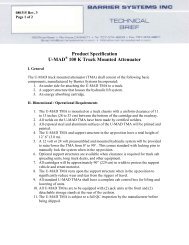
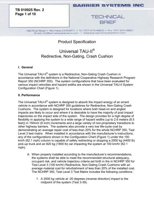
TB 010925 Rev. 2Page 1 of 10Product SpecificationUniversal TAU-<strong>II</strong> ®Redirective, Non-Gating, Crash CushionI. GeneralThe Universal TAU-<strong>II</strong> ® system is a Redirective, Non-Gating Crash Cushion inaccordance with the definitions in the National Cooperative Highway Research ProgramReport 350 (NCHRP 350). The system configurations that have been evaluated forvarious impact velocities and hazard widths are shown in the Universal TAU-<strong>II</strong> SystemConfiguration Chart (Figure 1).<strong>II</strong>. PerformanceThe Universal TAU-<strong>II</strong> ® system is designed to absorb the impact energy of an errantvehicle in accordance with NCHRP 350 guidelines for Redirective, Non-Gating CrashCushions. The system is designed for locations where both head-on and angledimpacts are likely to occur and where it is desirable to have the majority of post impacttrajectories on the impact side of the system. The design provides for a high degree offlexibility in applying the system to a wide range of hazard widths (up to 2.6 meters (8.5feet)) in 150mm (6 inch) increments and a large variety of non-proprietary transitions toother highway barriers. The systems also provide a very low life-cycle cost bydemonstrating an average repair cost of less than 20% for the whole NCHRP 350, TestLevel 3 test matrix. When installed in accordance with the manufacturer’s instructions,any of the configurations shown in the Configuration Chart (Figure 1) under the 100km/h (62.1 mph) column is capable of safely redirecting or stopping a 2000 kg (4400 lb)pick-up truck and an 820 kg (1800 lb) car impacting the system at 100 km/hr (62.1mph).A. When properly installed according to the manufacturer’s recommendations,the systems shall be able to meet the recommended structural adequacy,occupant risk, and vehicle trajectory criteria set forth in the in NCHRP 350 forTest Level 3 (100 km/hr) Redirective, Non-Gating Crash Cushions with anaverage material cost for refurbishment of less than 20% of the installed cost.The NCHRP 350, Test Level 3 Test Matrix includes the following conditions:1. A 2000 kg vehicle at -20 degrees (reverse direction) impact to themidpoint of the system (Test 3-39).
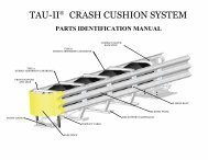
2. A 2000 kg vehicle at 20 degrees impacting at the Critical <strong>Impact</strong> Pointof the system. The critical impact point was determined to be the frontof the backstop along the centerline of the system (Test 3-38).3. A 2000 kg vehicle at 20 degrees impacting the side, near the front ofthe system (Test 3-37).4. An 820 kg vehicle at 20 degrees impacting the side, near the front ofthe system (Test 3-36).5. A 2000 kg vehicle at 15 degrees impacting the front of the system(Test 3-33).6. An 820 kg vehicle at 15 degrees impacting the front of the system(Test 3-32).7. A 2000 kg vehicle at 0 degrees and centered on the front of the system(Test 3-31).8. An 820 kg vehicle at 0 degrees and an offset of ¼ the width of thevehicle from the centerline of the system (Test 3-30).B. The impact velocity of a hypothetical front seat passenger against the vehicleinterior as calculated from the longitudinal vehicle acceleration and 600 mm[23 5/8 in] forward displacement, and the lateral vehicle acceleration and 300mm [12 in] lateral vehicle displacement, shall be less than 12 m/s (39.3 ft/s).The highest 10 ms average vehicle acceleration in the longitudinal and lateraldirections subsequent to the instant of hypothetical occupant impact shall beless than 20 g’s in the NCHRP 350 testing matrix of the Universal TAU-<strong>II</strong>system.Detached debris shall not show potential for penetrating the vehicle occupantcompartment or present a hazard to other traffic, pedestrians, or workers in awork zone. The vehicle shall remain upright during and after the collision,although moderate roll, pitch, and yaw may occur. Vehicle deformations shallnot cause intrusion into the occupant compartment in excess of 150 mm (6inches).<strong>II</strong>I. Description of SystemA. The Universal TAU-<strong>II</strong> crash cushion is made up of independent collapsiblebays that are guided and supported by high strength galvanized steel cables.The system’s energy capacity is provided by an array of Energy AbsorbingCartridges. The Universal TAU-<strong>II</strong> systems are available in various length andwidth configurations and with capacities as shown in the Universal TAU-<strong>II</strong>System Configuration Chart (Figure 1). All of these configurations can beassembled from the basic parts as shown in the Universal TAU-<strong>II</strong> Parts List(Figure 2). The systems shall be made up of the following components andshall be fabricated from materials conforming to the following specifications:TB 010925 Page 2 of 10
1. The foundation system for the Universal TAU-<strong>II</strong> consists of two cables,a Back Support and Front Cable Anchors as shown in Figure 2 orFigure 3. The Front Cable Anchor weighs approximately 35 kg (75 lb).The types of Cable Anchors and Back Supports can be selected fromthose shown in Figures 2 and 3 based on the requirements of thespecific site.a. All steel structural components of these assembliesshall be fabricated from mild steel in conformancewith ASTM A-36 specifications. Thesecomponents are hot dipped galvanized per ASTMA-123.b. Fasteners shall be Class 5.8 (Grade 2) or greaterand galvanized in accordance with ASTM 153.Washers shall be hardened and galvanized.c. The steel cables shall be at least 25 mm (1 in)diameter and galvanized in accordance with ASTMA-603.2. Front and Middle Supports and the various sizes of Bulkheads (XL,XXL and XXXL) (Figure 2) separate each independent collapsible bay.Cable Guides bolt to the Middle Supports and Bulkheads, capturing thecables and connecting the bays to the foundation system.a. All Front and Middle Supports, Bulkheads andcable guides shall be fabricated from mild steel inconformance with ASTM A-36 specifications.These components are hot dipped galvanized perASTM A-123.b. All fasteners shall be Class 5.8 (Grade 2) orgreater and galvanized in accordance with ASTM153. Washers shall be hardened and galvanized.3. Each Bay is enclosed on the sides with Sliding Panels. Sliding Boltsfasten the panels to the Front and Middle Supports and Bulkheads.End Panels are attached to the Back Support and the last bays’sSliding Panels through Pipe Panel Mounts and provide transitionmounting points. The Pipe Panel Mounts are bolted to the backsupport.a. Steel panels are to be fabricated from steel thatconforms to the requirements of AASHTO M180Class B.b. Sliding Bolts are to be cast from ASTM 1045 HTsteel and galvanized per ASTM A-123.TB 010925 Page 3 of 10
c. Steel Pipe Panel Mounts shall be fabricated frommild steel in conformance to ASTM A513, Type 5specifications.d. Fasteners shall be Class 5.8 (Grade 2) or greaterand galvanized in accordance with ASTM 153.Washers shall be hardened and galvanized.4. Flexible Front Support Legs and a Nose Piece mount to the FrontSupport. The Front Support Legs and Nose Piece are bolted in place.The Nose Piece provides a location to attach suitable delineation inconformance with local specifications (to be supplied by others).a. The front support legs shall be fabricated fromeither synthetic or natural rubber or polyurethane.b. The Nose Piece shall be fabricated frompolyurethane.c. All fasteners shall be Class 5.8 (Grade 2) orgreater and galvanized in accordance with ASTM153. Washers shall be hardened and galvanized.5. Two types of Energy Absorbing Cartridges (Figures 4 and 5) providethe primary energy absorbing capacity for the system. The cartridgesappear as cylindrical plastic containers measuring approximately 775mm (30 ½ in) in length and approximately 635 mm (25 in) in diameter.Each cartridge weighs approximately 16 kg (35 lb).a. All plastic parts shall be molded from speciallyformulated High Density Cross-linked Polyethylene.B. The Universal TAU-<strong>II</strong> systems are available in various capacities, eachrequiring a specific configuration of Energy Absorbing Cartridges (Types Aand B). The capacities and configurations are shown in the Universal TAU-<strong>II</strong>System Configuration Chart (Figure 1).C. The Universal TAU-<strong>II</strong> system shall require attachment to a foundation.Anchoring of the system will require attachment in accordance with themanufacturer’s drawings and instructions. Anchor capacity will require 12000kg (25000 lb) pull out and 8500 kg (19000 lb) shear strength.D. The TAU-<strong>II</strong> system shall be assembled, installed, and refurbished inaccordance with the manufacturer’s instructions.IV. Application of Safety AppurtenancesHighway safety appurtenances should be applied to hazardous sites in accordance withthe guidelines and recommendations in the American Association of State HighwayTB 010925 Page 4 of 10
Transportation Officials (AASHTO), “Roadside Design Guide”, and other FederalHighway Administration and State Department of Transportation requirements.Placement of the TAU-<strong>II</strong> system must comply with these specifications and guidelinesas well as those of the manufacturer.TB 010925 Page 5 of 10
Figure 1TB 010925 Page 6 of 10
Figure 2 TB 010925 Page 7 of 10
Figure 3TB 010925 Page 8 of 10
Figure 4 TB 010925 Page 9 of 10
Figure 5 TB 010925 Page 10 of 10