DRAGNET® - Impact Absorption Inc
DRAGNET® - Impact Absorption Inc
DRAGNET® - Impact Absorption Inc

Create successful ePaper yourself
Turn your PDF publications into a flip-book with our unique Google optimized e-Paper software.
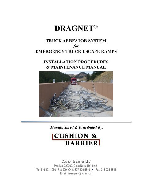
DRAGNET ®<br />
TRUCK ARRESTOR SYSTEM<br />
for<br />
EMERGENCY TRUCK ESCAPE RAMPS<br />
INSTALLATION PROCEDURES<br />
& MAINTENANCE MANUAL<br />
Manufactured & Distributed By: <br />
Cushion & Barrier, LLC<br />
P.O. Box 220292, Great Neck, NY 11021<br />
Tel: 516-498-1050 / 718-229-0046 / 877-229-5819 Fax: 718-225-2845<br />
Email: mkempen@nyc.rr.com
CUSHION & BARRIER, LLC<br />
DRAGNET ®<br />
TRUCK ARRESTOR SYSTEM FOR<br />
EMERGENCY TRUCK ESCAPE RAMPS<br />
INSTALLATION PROCEDURES<br />
& MAINTENANCE MANUAL <br />
C O N T E N T S<br />
Introduction…………………………………………………….. 4<br />
Page<br />
General Description/<br />
Principles of Operation……………………………………….... 5-9<br />
Maintenance Instructions………………………………………. 10-11<br />
Installation Instructions………………………………………... 12-13<br />
Photos of Current Installations……………………………….... 14-20<br />
Design Development of a Truck Escape Ramp…………........... 21-24<br />
Newspaper Articles Re: Dragnet………………………………. 25-27
CUSHION & BARRIER, LLC<br />
INTRODUCTION<br />
Large commercial vehicles which have lost control in hilly terrain present a<br />
major challenge to engineers concerned with highway safety. The desired criteria<br />
for constructing escape ramps is to stop a 90,000 lb. (36,400 kg) truck entering<br />
the ramp at 90 mph (129 km/hr) with a deceleration of 0.8 “G” or less.<br />
The most common approach to this problem is the construction of truck<br />
emergency escape ramps employing deep-gravel arrestor beds. In this approach,<br />
a separate lane is constructed off the main road. This lane, or ramp is typically<br />
one hundred to two hundred meters in length and surfaced with either riverbed<br />
gravel or angular crushed gravel in depths varying from one to two meters.<br />
While these arrestor beds are generally effective in bringing an out-of-control<br />
truck to a stop, there are many serious drawbacks to their use. First there is the<br />
problem of extracting the stopped truck from the arrestor bed, since it is now<br />
mired up to its axles in deep gravel. A high-capacity tow truck is usually<br />
required. Even then some means of rigid under-wheel planking will be needed to<br />
distribute the load more evenly as the truck is being hauled out. The pitching and<br />
yawing of the truck as it enters the bed is yet another disadvantage of this type of<br />
escape ramp. Gravel arrestor beds also scatter rock debris into work areas.<br />
Finally, cargo shift is always a concern with a gravel type arrestor bed.<br />
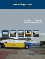
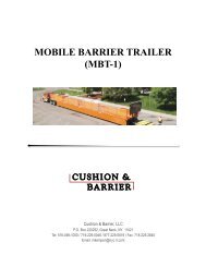
In their search for an improved truck arrestor system, Cushion & Barrier’s<br />
engineers have modified and tested a ramp equipped with a series of Dragnet<br />
Systems which can be easily erected on a paved surface equipped with<br />
longitudinal concrete median barriers on both sides.<br />
The Dragnet System is currently manufactured by Cushion & Barrier, LLC in<br />
the New York Metropolitan area. The technology was first used by the Navy to<br />
stop aircraft landing on aircraft carriers. The system was adapted and tested for<br />
highway applications in the early seventies. Cushion & Barrier, LLC began<br />
marketing the device for roadside applications in the eighties. Since then the<br />
Dragnet System has been used for road closures for construction, movable<br />
bridge closures, HOV lanes and ferry terminals.<br />
The first application for a truck escape ramp was in 1992 with an installation in<br />
Horseshoe Bay, British Columbia. Since then ramps have been installed in<br />
Hawaii, Biarritz, France, Williamstown, MA, North Bay, Canada, Buffalo,<br />
Wyoming and Avon, CT. Systems are currently under consideration in Australia,<br />
and other locations in Canada and America.<br />
4
CUSHION & BARRIER, LLC<br />
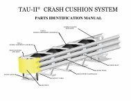
GENERAL DESCRIPTION<br />
The Dragnet Emergency Truck Escape Ramp consists of a series of vehicle<br />
restraining devices (Energy Absorbers and Barrier Nets). The restraining devices<br />
are mounted in concrete median barriers located on each side of the escape ramp.<br />
Should an out-of-control truck enter the ramp, it will sequentially encounter the<br />
restraining devices. (Each absorber provides a constant restraining force<br />
throughout the allowed run-out distance. The force in the system increases until<br />
sufficient kinetic energy is absorbed to bring the truck to a safe stop.) The first<br />
net in the series is designed to stop out of control automobiles as well as trucks,<br />
and is different from the balance of the nets used in the system.<br />
PRINCIPLES OF OPERATION<br />
The vehicle restraining device includes a steel cable-type net, attached at each<br />
end to an Energy Absorber. The nets are held across the escape ramp in a<br />
vertical position by tensioning devices. The Energy Absorbers are embedded in<br />
the concrete footings.<br />
Each Energy Absorber is comprised of a stainless steel chamber with an enclosed<br />
200 foot-long steel tape. When the barrier is truck, the steel tape is pulled from<br />
the Energy Absorbers over a series of five offset shoulder bolts, imparting a<br />
restraining (bending) force to the steel tapes, which in turn slows and stops the<br />
vehicles. The steel tapes MUST be replaced after each vehicle impact.<br />
5
CUSHION & BARRIER, LLC<br />
The Dragnet System energy absorber units are rated, first by the amount of force<br />
needed to initiate pull on the tape. The second consideration is the length of tape<br />
provided. The following is a list of our standard units.<br />
The following chart has been developed for a standard unit, designed for 4,500<br />
pound restraints at each terminal with a 200 foot tape. Larger units, with up to<br />
25,000 lb. restraints, are available. As a result, the Dragnet can be designed to<br />
stop trucks and other heavy vehicles at high speeds with “G” forces well under the<br />
current Federal guidelines.<br />
DRAGNET PROVIDES FOR LOWER “G” FORCES<br />
Also of paramount importance in the design of any impact attenuator are the “G”<br />
forces involved in bringing the vehicle to a complete stop. Here the Dragnet has<br />
no equal. In addition to a multitude of instrumented tests at Federally approved<br />
testing facilities, Cushion & Barrier, LLC has performed several demonstrations<br />
using live drivers. In all of the impacts at speeds in excess of 60 mph (100 Kph),<br />
no occupant injury was experienced and vehicular damage was negligible.<br />
6
CUSHION & BARRIER, LLC<br />
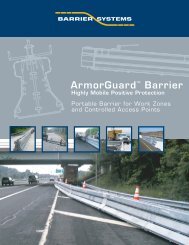
Advantages of the Dragnet for Truck Escape Ramps<br />
Safe, Controlled Deceleration of Vehicles:<br />
The Dragnet System can stop vehicles of all sizes, from 1800 lb. compacts to a fully<br />
loaded eighteen wheeler, safely. Occupant ride down decelerations are well within<br />
FHWA standards. The system can be designed to maintain restraining forces below .5<br />
“G” to alleviate trailer load-shift and jackknifing.<br />
System Flexibility:<br />
The arrestors can be designed for any speed or any vehicle weight within a range of<br />
drive-down deceleration rates. This allows the designer greater latitude in establishing<br />
design variables to manipulate ramp lengths. Our duel arrestor system enables a<br />
lightweight vehicle to use escape ramps and be stopped safely as well as fully loaded<br />
trucks. The Dragnet System may be utilized on positive or negative grades.<br />
Economical Alternative:<br />
The Dragnet can provide substantial savings from the cost of typical gravel bed<br />
designs by minimizing the amount of construction and fill that is typically required.<br />
Ramps generally can be shorter in length with the Dragnet and do not require<br />
adjacent paved service lanes or chain pull anchors for vehicle removal.<br />
Ease of Maintenance:<br />
A truck escape ramp utilizing the Dragnet System avoids the freeze/thaw problems<br />
which gravel beds experience. Roadway surfaces are bituminous paved so ramp<br />
performance is relatively unaffected by severe winter conditions. The Dragnet<br />
System component parts require only minimal periodic maintenance.<br />
Ease of Repair:<br />
After an impact the Dragnet System is easily repaired, often requiring only the<br />
replacement of the spool of tape used in the arrestors. Repair times are usually less<br />
than an hour/net and can be accomplished by local tradesmen without special tools.<br />
Tested & Proven:<br />
This technology was originally developed and used by the Navy to stop planes aboard<br />
aircraft carriers. It has since been adapted and tested under FHWA standards for a<br />
variety of applications on our nation’s highways and meets NCHRP 350 design<br />
criteria. The Dragnet has been tested for a wide range of vehicle sizes, design speeds<br />
and impact angles.<br />
Minimal Engineering:<br />
Specifications, plans, and drawings currently available can be easily modified to suit<br />
any particular site. The system easily accommodates variable design criteria such as<br />
vehicle speed and weight, angle of incidence and anchor requirements.<br />
Approved & Refundable:<br />
The Dragnet has been approved for use by the FHWA and qualifies under the federal<br />
8020 funding program as an impact attenuator for 100% federal funding.<br />
7
CUSHION & BARRIER, LLC<br />
SAMPLE DESIGN CALC. FOR A DRAGNET TRUCK ESCAPE RAMP<br />
DESIGN WITH STANDARD 4500# X 200' ARRESTOR TAPES NUMBER OF ARRESTORS: 8 Single Arrestor Nets<br />
VEHICLE SPEED: 60 MPH (88 ft./sec.) AVERAGE "G" LEVELS: 0.41<br />
GRADE: 6% Down Slope EST. STOPPING DISTANCE: 290 ft.<br />
STATION RESTRAINING DISTANCE BET. SPEED SPEED AVERAGE "G's"<br />
(ft.) FORCE STATIONS (ft.) ft./sec. mph BET. STATIONS<br />
0 9000 40 88 60 0.1<br />
40 18000 10 86.46 58.95 0.32<br />
50 27000 10 85.26 58.13 0.74<br />
60 36000 10 82.40 56.18 0.72<br />
70 4500 130 79.55 54.24 0.73<br />
200 4500 40 31.74 21.64 0.28<br />
240 4500 10 17.03 11.61 0.17<br />
250 4500 40 13.35 9.11<br />
ESTIMATED COST OF DRAGNET SYSTEM:<br />
EIGHT NET & ARRESTOR ASSEMBLIES = $16,500 X 8 = $132,000<br />
INSTALLATION: 2 MEN X 2.5 HR. / NET = 5 MAN HRS. X 8 NETS = 40 MAN HRS.<br />
8
CUSHION & BARRIER, LLC<br />
9
CUSHION & BARRIER, LLC<br />
MAINTENANCE INSTRUCTIONS<br />
<br />
Scheduled Maintenance<br />
1. Weekly<br />
a. Visual Inspection<br />
The purpose of this inspection is to spot any unusual conditions<br />
which would prevent the system from functioning as designed.<br />
These conditions include misalignment, loose fasteners, cable<br />
damage, corrosion, vandalism, etc.<br />
b. Check the barrier net for proper tension and proper height. The<br />
barrier net should be perpendicular to the roadway within 5<br />
degrees.<br />
c. Check for any build up of trash or dirt around the Energy<br />
Absorbers which could interfere with proper operation.<br />
2. Yearly<br />
a. Open Energy Absorber Housing and inspect for severe corrosion.<br />
Excessive corrosion will necessitate the need for tape<br />
replacement. Excessive white milky substance on the tape or<br />
areas of rust larger than the size of a quarter are cause for<br />
replacement of the tape.<br />
<br />
Adjustments – Net Tension<br />
1. Once the Barrier Net has been properly installed between the Energy<br />
Absorbers, the final adjustment is made by tightening the turnbuckles.<br />
The turnbuckles are located between the net end plates and the<br />
Energy Absorber foundations. A large screwdriver or a small pinch<br />
bar can be used to adjust the length of the turnbuckle and increase or<br />
decrease the tension in the net. Both ends of the net must be adjusted<br />
equally to balance the tension. Do not over tension the net. Tension<br />
should be such that the net is upright and stable, and the cable sag at<br />
the center is no greater than 1 ½”.<br />
10
CUSHION & BARRIER, LLC<br />
MAINTENANCE INSTRUCTIONS Cont’d<br />
<br />
Refitting After Vehicle <strong>Impact</strong><br />
1. Replacing the Net<br />
The entire Barrier Net and Energy Absorbers can be replaced as<br />
follows:<br />
First, remove the net from the Energy Absorber by removing the<br />
½-13 bolt and nut at each end of the net with an open-end or box<br />
wrench.<br />
Second, remove the pipe from the concrete median barrier.<br />
The Energy Absorbers can now be lifted out from the slot in the<br />
median barrier. The Energy Absorber then needs to have a new<br />
replacement tape installed in the chamber.<br />
Tape replacement should be made in accordance with the Installation<br />
Instruction contained in this manual.<br />
11
CUSHION & BARRIER, LLC<br />
INSTALLATION INSTRUCTIONS<br />
<br />
Energy Absorber Installation<br />
1. Connect pipe cap to top of pipe.<br />
2. Insert Energy Absorber into the top slot of the concrete median barrier<br />
with spacer underneath.<br />
3. Line up spacer and Energy Absorber mounting hole with the hole in<br />
top of concrete barrier.<br />
4. Insert pipe with cap through holes in concrete barrier, Energy<br />
Absorber, and spacer.<br />
5. Insert Energy Absorber into the bottom slot of the concrete median<br />
barrier with spacer underneath.<br />
6. Line up spacer and Energy Absorber mounting hole with the hole in<br />
top of concrete barrier.<br />
7. Insert pipe with cap through holes in concrete barrier, Energy<br />
Absorber, and spacer.<br />
<br />
Net Installation<br />
1. Unroll the assembly across the ramp between the Energy<br />
Absorbers. Net #1 must have the bottom lower cable slanted away<br />
from oncoming traffic.<br />
2. Remove the ½-13 bolts and self-locking nut from the net attachment<br />
fitting at the end of each Energy Absorber tape. Connect this fitting<br />
to the net end plates as shown, using the same bolt and nut. Install<br />
turnbuckles, pivot plates and “L” brackets.<br />
3. Place the bottom cable into the net and replace the bolts and nuts.<br />
12
CUSHION & BARRIER, LLC<br />
INSTALLATION INSTRUCTIONS Cont’d<br />
4. Tighten turnbuckles enough to make the net stand up on the center<br />
support post.<br />
5. Gradually tighten the turnbuckles, alternating from one end of the net<br />
to the other until the net sag is reduced to provide the clearances<br />
between the road surface and the bottom cable. Net #1 – bottom<br />
cable to road surface is 10” +/- 1 inch. For the other nets the bottom<br />
cable to road surface is approximately 20” +/-1 inch.<br />
<br />
Replacing Energy Absorber Tape<br />
1. Remove the five 5/16-18 lock nuts from the bottom of the Energy<br />
Absorber and lift the five shoulder bolts from the top of the cover.<br />
2. Remove the fourteen ¼-20 hex-head screws and lock nuts from the<br />
Energy Absorber cover. Lift the cover from the chamber. Remove<br />
the expended tape.<br />
3. Remove the single ½-13 bolt and lock nut from the net fitting and save<br />
parts for re-use. Discard the expended tape.<br />
CAUTION!<br />
Energy absorber tapes are specially lubricated. Store only in a clean, dirt<br />
free, dry environment to ensure proper operation.<br />
4. Install the replacement tape exactly as shown in attached<br />
figure, drawing SK-5307, in order to provide the design restraining<br />
capability. Note carefully the position of the shoulder bolt holes and<br />
the preformed tape-end configuration. Replace the five shoulder<br />
bolts and lock nuts (do not tighten at this time) and reinstall the<br />
fourteen ¼-20 screws and lock nuts. Replace the salvaged ½-13 bolt,<br />
busing and lock nut from the expanded tape. Tighten all bolts.<br />
Replacement is now complete.<br />
CAUTION!<br />
The Energy Absorber and Barrier Net System described above is part of a<br />
highly loaded system, designed to safely stop out of control cars and<br />
trucks. In order for this system to operate properly, each part must have<br />
the form, fit, function, and reliability that was designed and specified by<br />
the manufacturer. Replacement parts should always be obtained from the<br />
original supplier of this equipment to assure proper operation. Common<br />
hardware items procured locally may look the same as those being<br />
replaced, but may not perform properly when subject to the loads imposed<br />
on the system.<br />
13
CUSHION & BARRIER, LLC<br />
British Columbia, Canada<br />
14
CUSHION & BARRIER, LLC<br />
British Columbia, Canada<br />
15
CUSHION & BARRIER, LLC<br />
Buffalo, Wyoming<br />
16
CUSHION & BARRIER, LLC<br />
Buffalo, Wyoming<br />
17
CUSHION & BARRIER, LLC<br />
Buffalo, Wyoming<br />
18
CUSHION & BARRIER, LLC<br />
North Bay, Ontario, Canada<br />
19
CUSHION & BARRIER, LLC<br />
Avon, Connecticut<br />
20
CUSHION & BARRIER, LLC<br />
DESIGN DEVELOPMENT OF A<br />
TRUCK ESCAPE RAMP<br />
21
CUSHION & BARRIER, LLC<br />
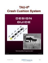
THE DRAGNET SYSTEM<br />
The Dragnet Truck Arrestor System is patented and manufactured by Cushion<br />
& Barrier, LLC of the New York Metropolitan area. The system is an outgrowth<br />
of the crash nets formerly used on aircraft carriers.<br />
It has seen widespread use in the United States to safely stop passenger vehicles<br />
from intruding into perilous areas such as construction zones, open drawbridges,<br />
reversible traffic lanes, railroad crossings, emergency road closures, etc. It is<br />
designed to stop errant vehicles with very low accelerations and minimal<br />
damage. A typical system consists of a net made of a continuous steel cable and<br />
chain link fence attached at each end to energy absorbers. The energy absorbers<br />
are supported by anchor posts that are embedded into the pavement or the road<br />
shoulder or attached to longitudinal barriers. These energy absorbers, which are<br />
the heart of the Dragnet System, are steel chambers containing a series of<br />
staggered rollers around which a long length of metal tape or strap is bent back<br />
and forth as it is pulled through this deformation chamber. Each end of the net is<br />
attached to one end of these metal tapes protruding from the energy absorber<br />
case. These energy absorbers are designed so that a specific force is required to<br />
pull the tape through the chamber. This force is constant and not dependent on<br />
the impact velocity or environmental conditions. It is rather a function of the<br />
geometry and the material properties of the tape material. Basically, the<br />
capability of the system to absorb kinetic energy is the product of the restraining<br />
force of both energy absorbers and the runout distance of the metal tapes.<br />
Equation 1 where:<br />
C = T (R 1 = R 2 )<br />
C = capacity of Dragnet<br />
T = pullout force of one energy absorber<br />
R 1 = runout distance of left side absorber<br />
R 2 = runout distance of right side absorber<br />
Dragnet System absorber units are rated first by the amount of force needed to<br />
initiate pull of the tape. The absorber units are provided in differing lengths as<br />
follows:<br />
Rated Pull Out Force Tape Length<br />
4,500 pounds (20.016 kilonewtons) 75 feet (22.86 meters)<br />
4,500 pounds (20.016 kilonewtons) 200 feet (60.96 meters)<br />
18,000 pounds (80.064 kilonewtons) 40 feet (12.19 meters)<br />
25,000 pounds (111.20 kilonewtons) 100 feet (30.44 meters)<br />
22
CUSHION & BARRIER, LLC<br />
As there is one absorber at each end of the fence or net assembly, a hit<br />
automatically activates both absorbers. Therefore, to calculate total capacity, the<br />
combined energy force of two absorbers must be used. By reference to Equation<br />
1, we can then determine the attenuating capacities for these standard units as<br />
follows:<br />
2 Units of 4500 lbs with 75 foot tapes……. 675,000 ft lbs (915.132 kn m)<br />
2 Units of 4500 lbs with 200 foot tapes…... 1,800,000 ft lbs (2440.351 kn m)<br />
2 Units of 18,000 lbs with 40 foot tapes….. 1,440,000 ft lbs (1951.960 kn m)<br />
2 Units of 25,000 lbs with 100 foot tapes… 5,000,000 ft lbs (6778.753 kn m)<br />
By equating these capacities to the kinetic energy of an impacting vehicle we can<br />
calculate the maximum permissible impact velocity of a given weight car. This<br />
has been done for a range of vehicles in Table 1 for the 4500 lb Energy Absorber<br />
with 75 foot tapes and in Table 2 for the 4500 lb Energy Absorber with 200 foot<br />
tapes. Tables 1A and 2A report the same data in the metric system. It should be<br />
noted that these values are somewhat conservative since only the restraining for<br />
of the tapes has been considered effective in stopping the vehicle. Other factors<br />
such as tire friction, braking, and aerodynamic drag have been ignored.<br />
The maximum theoretical acceleration is simply the restraining force in the tapes<br />
divided by the weight of the vehicle and can only be approached when the tapes<br />
are parallel to the velocity vector of the impacting vehicle. Initial accelerations<br />
are much lower.<br />
The Dragnet System has been extensively tested for a wide variety of vehicle<br />
weights up to speeds of 70 mph (112.7 km/hr) and it impacts angles up to 30 o .<br />
Many in-service reports have substantiated the excellent performance of the<br />
Dragnet System in the field.<br />
23
CUSHION & BARRIER, LLC<br />
24
CUSHION & BARRIER, LLC<br />
25
CUSHION & BARRIER, LLC<br />
26
CUSHION & BARRIER, LLC<br />
27
Manufactured & Distributed By: <br />
Cushion & Barrier, LLC<br />
P.O. Box 220292, Great Neck, NY 11021<br />
Tel: 516-498-1050 / 718-229-0046 / 877-229-5819 Fax: 718-225-2845<br />
Email: mkempen@nyc.rr.com