CPFC - Arizona Nanotechnology Cluster
CPFC - Arizona Nanotechnology Cluster
CPFC - Arizona Nanotechnology Cluster

You also want an ePaper? Increase the reach of your titles
YUMPU automatically turns print PDFs into web optimized ePapers that Google loves.
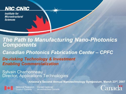
The Path to Manufacturing Nano-Photonics<br />
Components<br />
Canadian Photonics Fabrication Center – <strong>CPFC</strong><br />
De-risking Technology & Investment<br />
Enabling Commercialization<br />
Sylvain Charbonneau<br />
Director, Applications Technologies<br />
<strong>Arizona</strong>’s Second Annual <strong>Nanotechnology</strong> Symposium, March 23 rd , 2007
NRC: A National Institution<br />
• National organization,<br />
federal government agency<br />
• Provides essential<br />
elements of national S&T<br />
infrastructure<br />
• 4,116 employees<br />
• 1,446 visiting / guest<br />
workers<br />
• Labs and facilities across<br />
the country<br />
• Total expenditures<br />
2005-06: $767M<br />
• Income 2005-06: $103M
Major Research Thrusts<br />
• Information and communications<br />
• Biotechnology<br />
• <strong>Nanotechnology</strong><br />
• Manufacturing<br />
• Aerospace, construction and<br />
ocean technologies<br />
• Metrology<br />
• Astronomy
IMS Mission<br />
• To play a pivotal role in the creation and<br />
development of photonic, optical and<br />
quantum devices<br />
• Ensure diffusion into the Innovation<br />
System<br />
• Communications, Health, Environment,<br />
Energy and Security
IMS at a glance<br />
Locations: Ottawa<br />
M50, M23-A, M36<br />
Budget - IMS: $14M (+$5M)<br />
- <strong>CPFC</strong>: ($43M/5yrs)<br />
Staff: 160 (~95PhD)<br />
Guest workers: ~40<br />
Publications: ~180/year<br />
Technologies: ~100<br />
Spin-offs: 6+1 (since 1996)
Core Competencies<br />
• Semiconductors:<br />
inorganic & organic<br />
• Nanofabrication<br />
• Photonic & Quantum Devices<br />
• PIC & Component Prototyping<br />
• Optical Interference Coatings<br />
• Optics Shop<br />
• Acoustics<br />
Energy Gap (eV)<br />
GaN<br />
2.5<br />
2.0<br />
1.5<br />
1.0<br />
0.5<br />
0.0<br />
AlP<br />
GaP<br />
Si<br />
GaNAs<br />
Ge<br />
AlAs<br />
GaAs<br />
InGaAs<br />
InGaNAs<br />
InP<br />
InAs<br />
AlSb<br />
GaSb<br />
InGaAsSb<br />
InSb<br />
5.4 5.6 5.8 6.0 6.2 6.4 6.6<br />
Lattice Constant (A)<br />
0.5<br />
0.8<br />
1.55<br />
2.0<br />
5.0<br />
Wavelength (micron)
IMS activities 2007<br />
THz &<br />
Imaging<br />
Optoelect<br />
Devices<br />
Organic<br />
Devices<br />
Quantum<br />
Physics<br />
Quantum<br />
Theory<br />
Epitaxy &<br />
MultiLayer<br />
Surfaces /<br />
Interfaces<br />
NanoFab Optics Photonic<br />
Systems<br />
<strong>CPFC</strong> Acoustics Example<br />
partnersr<br />
COMMUNICATIONS<br />
QI: Nanoelectronics • • • • • • DARPA<br />
QI: Nano-Photonics • • • • • • CIAR<br />
CNTs for EL-FETs • • • • Japan S&T<br />
GaN HFETs • • • • • CSA<br />
High Contrast OLEDs • • • industry<br />
Wavelength Mtg • • • • DND<br />
HEALTH<br />
THz & Imaging • • • • • • GHI<br />
BioFETs • • • GHI<br />
Micro-Photonics • • • • • GHI<br />
Optical Probes • • • CIPI<br />
Hearing Aids • industry<br />
ENVIRON & ENERGY<br />
Mid-iR Lasers • • • • • • • • industry<br />
PhotoVoltaics • • • • • ICPET<br />
TECH PLATFORMS<br />
Acoustics • industry<br />
Device Prototyping • industry
Self-Assembled<br />
Quantum Dots (SAQD)
(001)<br />
SAQD - Basis for<br />
Single Photon Emitter<br />
(101) (011)<br />
SiO 2 mask<br />
InP pyramid<br />
InAs<br />
dots<br />
Advantages:<br />
Fully in-situ development of<br />
structures for single dot<br />
spectroscopy.
Electrical connection<br />
of Single QDs
Single Photon Gun<br />
Transmission [%]<br />
100<br />
80<br />
60<br />
40<br />
20<br />
CAVITY RESPONSE<br />
PL Intensity [a.u.]<br />
Design: 8 pair mirrors<br />
500 μeV<br />
535μeV<br />
0<br />
650 700 750 800 850 900 950 1000 1050<br />
Energy [meV]<br />
830 835 840 845 850 855 860 865<br />
Energy [meV]
Nano Electronics -<br />
controlling electrons<br />
on the nanoscale<br />
Challenge:<br />
How to control<br />
one out of many?
1995 NATO Workshop<br />
Increased miniaturisation:<br />
“The writing is on the wall”<br />
(but it is getting smaller!)<br />
Year to achieve production feature size:<br />
1991 1996 2000 ??<br />
1000<br />
Why smaller features?<br />
– lower cost<br />
– faster performance<br />
– lower power<br />
– higher integration<br />
Lithographic limits:<br />
– driven by eg RAMs<br />
– devices and interconnect<br />
Physical lim its:<br />
– ‘handful of electrons’<br />
– upset resilience<br />
– interconnect delay<br />
Number<br />
of<br />
electrons<br />
in a<br />
channel<br />
100<br />
10<br />
1<br />
10 11<br />
electrons.cm -2<br />
10 12<br />
electrons.cm -2<br />
1.0 0.6 0.2 0.1 0.06 0.02 0.01<br />
channel length (& width) in m icrons
Single Electron Transistor:<br />
Surface Gates<br />
90 nm<br />
LOCALIZING<br />
CONTROLLED NUMBER<br />
OF ELECTRONS 1-100<br />
AlGaAs<br />
GaAs<br />
2D electron gas at<br />
GaAs/AlGaAs<br />
SOURCE<br />
POTENTIAL<br />
ENERGY<br />
LANDSCAPE<br />
DRAIN
Artificial<br />
Atoms and Molecules<br />
QUANTUM DOT<br />
P QPC<br />
QPC
Spin-charge readout (DL & DPDiV)<br />
CNOT & CPHASE…<br />
3-dots-in-a-line device<br />
SINGLE CQD<br />
MESA<br />
3-dots-in-a-circle device<br />
4-dot-array device<br />
DARPA QuIST project (2001-06):<br />
“NRC-IMS: 3- 3 & 4-laterally 4<br />
coupled<br />
vertical semiconductor quantum dots<br />
for spin-qubit circuits"<br />
4-dot-array device<br />
Entanglement & coded qubits<br />
CNOT & CPHASE…
Single Wall –<br />
Carbon Nanotubes<br />
Single SWNT PL<br />
-strong, polarized, sub-k B T width<br />
-diameter dependent peak position<br />
see J. Lefebvre et al. PRB 69 075403 (2004)<br />
& PRL 90 217401 (2003)
Silicon nitride<br />
passivation<br />
20 nm AlGaN<br />
1 nm AlN<br />
200 nm GaN<br />
2µ C:GaN<br />
20 nm AlN<br />
Sapphire or SiC<br />
Ni/Au or Pt/Au<br />
Gate<br />
Primary Focus: GaN<br />
power transistors<br />
(HFETS)<br />
Alloyed n-type contacts<br />
AlGaN barrier layer<br />
AlN spacer layer<br />
Undoped channel layer<br />
Insulating C-doped<br />
isolation layer<br />
Nucleation layer<br />
Robust and well-established fabrication sequence yielding 0.8µ<br />
optically defined gates
Fully processed 2 inch<br />
GaN on SiC wafer
GaN power<br />
transistors (HFETS)<br />
- DC and RF results<br />
E-beam written T-gates; 0.15 µm gate length on SiC<br />
f T =103 GHz, f MAX =170 GHz<br />
Drain current (A/mm)<br />
1.4<br />
1.2<br />
1.0<br />
0.8<br />
0.6<br />
0.4<br />
0.2<br />
V g<br />
from 3 to -5 V, step -1 V<br />
Gain (dB)<br />
40<br />
30<br />
20<br />
10<br />
V ds<br />
=10 V<br />
V g<br />
=-2.5 V<br />
H 21<br />
UPG<br />
0.0<br />
0 5 10 15 20<br />
Source-drain voltage V ds<br />
(V)<br />
0<br />
10 100<br />
Frequency (GHz)
Ottawa Photonics Valley<br />
Canadian Photonics<br />
Fabrication Centre (<strong>CPFC</strong>)<br />
• Pure-play foundry service<br />
• Prototyping & Small Production<br />
• Unique facility in North America<br />
for industry and universities<br />
• Component and device<br />
fabrication<br />
• Linking photonics clusters to<br />
NRC's national facilities,<br />
networks, competencies and<br />
incubation services
NRC: Bridging the<br />
innovation gap<br />
Discovery,<br />
Basic Research<br />
Pre-competitive,<br />
Strategic Research<br />
Proof of Concept<br />
& Prototypes<br />
Industrial<br />
Innovation<br />
Products in the<br />
Marketplace<br />
UNIVERSITY RESEARCH<br />
NRC RESEARCH<br />
INDUSTRIAL RESEARCH<br />
<strong>CPFC</strong> – IRAP<br />
Value<br />
For<br />
Industry<br />
DISCOVERY TO INNOVATION TIMELINE
What is the Gap?
Mission<br />
<strong>CPFC</strong> Mission<br />
• To facilitate the commercialization and de-risking of photonic<br />
technology and investment by providing a world class industrial<br />
grade facility that bridges the gap from innovation to product.<br />
Core<br />
Technologies<br />
III - V<br />
Core Technology<br />
Silicon<br />
Strategy<br />
• Establish technology platforms and reusable<br />
process blocks in two materials<br />
sets<br />
• Fill up the “tool box” by demonstrating<br />
selected devices<br />
• Look for applications/clients in a broad<br />
range of markets (not just telecom)<br />
Competencies Applications<br />
• Design<br />
• Epiwafers<br />
• Processed wafers<br />
• Bars, Chips<br />
• Chip test<br />
PASSIVES & ACTIVES<br />
Telecom & Data<br />
FP Lasers, DFB lasers, PIN’s, Mux,<br />
Demux, TOS, OADM’s, R-OADM’s,<br />
Tuneable lasers, Modulators,<br />
Integrated TX + Rx, OCM’s, Spot size<br />
convertors<br />
Biophotonics<br />
Spectroscopy, Sensors, Imaging,<br />
Lasers<br />
Defense, Environmental,<br />
Security, Consumer<br />
• Design<br />
• Dielectrics & SOI<br />
• Processed wafers<br />
• Bars, Chips<br />
• Chip test<br />
PASSIVES & ACTIVES<br />
Telecom & Data<br />
Mux, Demux, TOS, OADM, R-OADM,<br />
SOB’s, Microfluidics, Splitters<br />
Biophotonics<br />
Spectroscopy, Sensors, Imaging<br />
Defense, Environmental,<br />
Energy, Imaging, Security,<br />
Consumer
Marketing Roadmap<br />
The <strong>CPFC</strong> has been engaging with a variety of customers representing a<br />
variety of markets. The distribution has been heavily weighted by telecom due<br />
to our location and the dependence telecom has for photonics. Other markets<br />
may represent higher growth potentials over the next few years.<br />
1. Communications<br />
2. Biomedical /Health<br />
3. Defense and Security<br />
4. Environmental<br />
5. Energy and Space<br />
Growth Rate<br />
Security & Defense<br />
Environment<br />
BioMedical / Health<br />
Telecom<br />
Energy<br />
Today<br />
Time<br />
3-5 years
<strong>CPFC</strong> Infrastructure<br />
Size: 40,000 ft 2 lab and office space<br />
Clean room : bay & chase configuration: total area 12,000 ft 2<br />
Personnel: 18 fab engineers & staff at present<br />
Epitaxy: MOCVD Multi-wafer reactor (2”, 3”, 4”, 6”)<br />
InP & GaAs-based<br />
Deposition:<br />
Lithography:<br />
Etchers:<br />
PECVD, LPCVD, and Thermal grown oxides<br />
Thick SiO 2<br />
(silica-on-silicon) & Thin SiO 2<br />
+ SiN<br />
Stepper, mask aligners, e-beam &<br />
nano-imprinting<br />
Stand alone for deep oxide, Si & III-V<br />
Metallization:<br />
e-beam & sputtering<br />
Leveraged on top of extensive existing IMS infrastructure:<br />
Device physics, Design & Modeling, Test & Characterization, Surface and<br />
Interfaces, Nanofabrication
Lithography<br />
Complete suite of resist tracks and exposure<br />
tools including:<br />
• Contact aligners (with backside alignment capability)<br />
• i-line stepper (with ~0.35µm resolution)<br />
• Holographic exposure tool (for uniform gratings to ~ 100nm<br />
resloution)<br />
• E-beam lithography (resolution 25nm) – not SEM<br />
• Nanoimprint lithography (resolution shown at 60nm)<br />
All set up for full wafer fabrication to achieve:<br />
• Uniformity<br />
• Process control<br />
• Reproducibility<br />
• Automated alignment (stepper, nanoimprint, e-beam)<br />
Emerging trend towards<br />
nanostructured devices
Electron beam lithography facility<br />
• 5 nm diam. spot<br />
• 20 nm lines<br />
JEOL JBX-6000 FS<br />
• 40 nm field<br />
stitching acc.<br />
• 150 x 150 mm<br />
write area<br />
• 200 mm wafers<br />
• 6” masks
Lithography process examples<br />
Stepper<br />
lithography<br />
1µm<br />
60nm<br />
High throughput<br />
E-beam<br />
lithography<br />
Low throughput<br />
Laser<br />
Holography<br />
200nm
Fabrication of<br />
DFB lasers<br />
1st order holographic gratings<br />
DFP Lasers<br />
25<br />
L = 300 μm; w = 2.4 μm; T = 20 C<br />
2<br />
0<br />
-10<br />
Power [mW]<br />
20<br />
15<br />
10<br />
5<br />
0<br />
0.4<br />
0 50 100 150 200<br />
Current [mA]<br />
Ith = 16.4 mA<br />
Eff = 0.22 W/A<br />
Rs = 8.0 Ohms<br />
DFB laser (CL/AR bar),<br />
W=2.4 μm, L=300 μm, T=20 °C, T 0<br />
=70 K<br />
Spectra at 100 mA<br />
1.8<br />
1.6<br />
1.4<br />
1.2<br />
1<br />
0.8<br />
0.6<br />
Voltage [V]<br />
Ith (mA<br />
Intensity [dBm]<br />
-20<br />
-30<br />
-40<br />
-50<br />
-60<br />
-70<br />
-80<br />
1534 1536 1538 1540 1542 1544<br />
Wavelength [nm]<br />
70<br />
RWG GC DFB Aging- 85 C, 70 mA<br />
65<br />
60<br />
55<br />
50<br />
45<br />
0 100 200 300 400 500 600 700 800<br />
Aging Time (hrs)<br />
DFB1<br />
DFB2<br />
DFB3<br />
DFB4<br />
DFB5<br />
DFB6<br />
DFB7<br />
DFB8<br />
DFB9<br />
DFB10
Surface Emitting BHET laser<br />
3.5<br />
3<br />
Top<br />
1.8<br />
1.6<br />
2.5<br />
1.4<br />
Power [mW]<br />
2<br />
1.5<br />
1.2<br />
1<br />
Voltage [V]<br />
1<br />
0.8<br />
0.5<br />
0.6<br />
Edge<br />
0<br />
0.4<br />
0 50 100 150 200<br />
Current [mA]<br />
E-beam gratings, etch<br />
& MOCVD overgrowth<br />
ICP etch, & MOCVD<br />
blocking layer selective<br />
regrowth<br />
P-metal patterned around<br />
aperture<br />
-30<br />
-40<br />
75 mA<br />
-50<br />
Intensity [dBm]<br />
-60<br />
-70<br />
-80<br />
-90<br />
-100<br />
<strong>CPFC</strong> Confidential<br />
1512 1514 1516 1518 1520 1522 1524<br />
Wavelength [nm]
<strong>CPFC</strong>’s Gateway to <strong>Nanotechnology</strong><br />
Cross-section 70nm lines (1 : 1.5)<br />
Template made by E-<br />
beam lithography and<br />
ICP etching<br />
Top view 70nm lines (1 : 1.5)
Gratings by nano-imprint lithography<br />
Fused silica<br />
template<br />
UV blanket<br />
exposure<br />
Planarization layer<br />
Substrate<br />
Step 1: Align template and substrate<br />
Step 4 : Expose with UV to harden imprint resist<br />
Imprint resist<br />
Step 2 : Create drop pattern with imprint resist<br />
Imprinted grating<br />
pattern<br />
Imprint resist fills<br />
template grating<br />
pattern<br />
Step 5 : Withdraw template from substrate<br />
Step 3 : Lower template and fill pattern<br />
Schematic showing step and flash imprint lithography (S-FIL)
Advantages and disadvantages of grating<br />
fabrication by NIL<br />
Advantages<br />
• Takes advantage of the resolution offered by electron beam<br />
lithography to pattern the template.<br />
• The resolution is only limited by the pattern resolution of the<br />
template.<br />
• The template can be used many times either for multiple fields per<br />
wafer or for the whole wafer printed at once, therefore providing a<br />
higher throughput than e-beam direct write.<br />
Disadvantages<br />
• A template must first be fabricated to imprint the gratings.<br />
• Imprinting is problematic on non-flat surfaces.
Grating metrology (pitch)<br />
Grating pitch for holographic gratings was<br />
measured by finding the difference between<br />
the Littrow angle of the grating and the angle<br />
of normal reflection. A set of 5 trials were<br />
taken without removing the wafer from the<br />
stage, the standard deviation was found to<br />
be less than 0.02 nm.<br />
The grating pitch uniformity for holographic<br />
gratings was assessed with measurements<br />
taken at 5 mm steps across a 3-inch wafer.<br />
There is a definite increase in grating pitch<br />
across the wafer, possibly caused by the wafer<br />
bending while held on the vacuum chuck.<br />
200.09<br />
200.07<br />
200.05<br />
Grating pitch [nm]<br />
200.03<br />
200.01<br />
199.99<br />
199.97<br />
199.95<br />
-30 -20 -10 0 10 20 30<br />
Distance from centre of wafer [mm]<br />
Holographic grating pitch repeat measurements taken<br />
from the centre of 3 separate 3-inch InP wafers.<br />
Holographic grating pitch measurement as a function<br />
of position from the centre of a 3-inch wafer.
<strong>CPFC</strong> - Summary<br />
Test<br />
Design<br />
Back -<br />
End<br />
Epitaxy<br />
<strong>CPFC</strong><br />
Metal<br />
Deposition<br />
Litho<br />
Etching`<br />
Complete Prototype Manufacturing:<br />
• Design & Modeling<br />
• Prototyping (controlled monitored<br />
processes)<br />
• Fabrication (i.e. specialized deposition or<br />
etch)<br />
• Specialty Masks & e-beam Lithography<br />
• Development (process change)<br />
• Epitaxial Services<br />
• Materials and Device Testing and Analysis<br />
• Consulting<br />
• Technology Licensing & Training
The <strong>CPFC</strong> will provide value by<br />
• Reducing start-up costs<br />
• Reducing time to market<br />
• De-risking the technology<br />
• De-risking the investment opportunity<br />
Bridging the gap to commercialization!
Canadian Photonics Fabrication Center