Advanced SVC models for newton-raphson load flow and ... - ITCJ
Advanced SVC models for newton-raphson load flow and ... - ITCJ
Advanced SVC models for newton-raphson load flow and ... - ITCJ

Create successful ePaper yourself
Turn your PDF publications into a flip-book with our unique Google optimized e-Paper software.
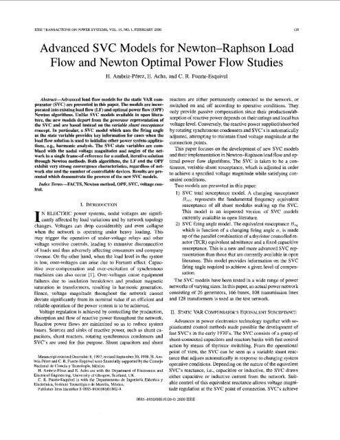
IEEE TRANSACTIONS ON POWER SYSTEMS. VOL. 15. NO. 1, FEBRUARY 2000 129<br />
<strong>Advanced</strong> <strong>SVC</strong> Models <strong>for</strong> Newton-Raphson Load<br />
Flow <strong>and</strong> Newton Optimal Power Flow Studies<br />
H. Amhriz-PBrez, E. Acha, <strong>and</strong> C. R. Fuerte-Esquivel<br />
Abstract-<strong>Advanced</strong> <strong>load</strong> <strong>flow</strong> <strong>models</strong> <strong>for</strong> the static VAR cumpensator<br />
(<strong>SVC</strong>) are presented in this paper. The <strong>models</strong> are incorporated<br />
into existing <strong>load</strong> <strong>flow</strong> (LF) <strong>and</strong> optimal power <strong>flow</strong> (OPF)<br />
Newton algorithms. Unlike <strong>SVC</strong> <strong>models</strong> available in open literature,<br />
the new <strong>models</strong> depart from the generator representation of<br />
the <strong>SVC</strong> <strong>and</strong> are based instead on the variable shunt susceptance<br />
concept. In particular, a <strong>SVC</strong> model which uses the firing angle<br />
as the state variable provides key in<strong>for</strong>mation <strong>for</strong> cases when the<br />
<strong>load</strong> <strong>flow</strong> solution is used to initialize other power system appliedtions,<br />
e.g., harmonic analysis. The <strong>SVC</strong> state variables are combined<br />
with the nodal voltage magnitudes <strong>and</strong> angles of the network<br />
in a single frame-of-reference fur U unified, iterative solution<br />
through Newton methods. Both algorithms, the LF <strong>and</strong> the OPF<br />
exhibit very strong convergence characteristics, regardless of network<br />
size <strong>and</strong> the number of controllable devices. Results are presented<br />
which demonstrate the prowess of the new <strong>SVC</strong> <strong>models</strong>.<br />
Index Terms-FACTS, Newton method, OPF, <strong>SVC</strong>, voltage control.<br />
I. INTRODUCTION<br />
N ELECTRIC power systems, nodal voltages are signifi-<br />
I cantly affected by <strong>load</strong> variations <strong>and</strong> by network topology<br />
changes. Voltages can drop considerably <strong>and</strong> even collapse<br />
when the network is operating under heavy <strong>load</strong>ing. This<br />
may trigger the operation of under-voltage relays <strong>and</strong> other<br />
voltage sensitive controls, leading to extensive disconnection<br />
of <strong>load</strong>s <strong>and</strong> thus adversely affecting consumers <strong>and</strong> company<br />
revenue. On the other h<strong>and</strong>, when the <strong>load</strong> level in the system<br />
is low, over-voltages can arise due to Ferranti effect. Capacitive<br />
over-compcnsation <strong>and</strong> over-excitation of synchronous<br />
machines can also occur [I]. Over-voltages cause equipment<br />
failures due to insulation breakdown <strong>and</strong> produce magnetic<br />
saturation in trans<strong>for</strong>mers, rcsulting in harmonic generation.<br />
Hence, voltage magnitudc throughout the network cannot<br />
deviate significantly from its nominal value if an efficient <strong>and</strong><br />
reliable operation of the power system is to bc achieved.<br />
Voltage regulation is achieved by controlling the production,<br />
absorption <strong>and</strong> <strong>flow</strong> of reactive power throughout the network.<br />
Reactive power <strong>flow</strong>s are minimized so as to reduce system<br />
losses. Sources <strong>and</strong> sinks of reactive power, such as shunt capacitors,<br />
shunt reactors, rotating synchronous condensers <strong>and</strong><br />
<strong>SVC</strong>’s are used <strong>for</strong> this purpose. Shunt capacitors <strong>and</strong> shunt<br />
Manuscript received December 8, 1997; revised September 30,1998. H. Ambriz-P6rez<br />
<strong>and</strong> C. R. Fuerte-Esqoivel were financially supported hy the Consejo<br />
Nacional de Ciencia y Tecnologiil, MCxica.<br />
H. Ambriz-PCrw <strong>and</strong> E. Acha are with the Department of Electronics <strong>and</strong><br />
Electrical Engineering, University of Glasgow, Scotl<strong>and</strong>, UK.<br />
C. R. Fuerte-Esquivel is with the Departamentu de Ingenieria EICctrica y<br />
Electrhica, Institute Tccnol6gico de March, Mexico.<br />
Publishcr Item Identifier S 0885-8950(110)01862-9.<br />
reactors are either permanently connected to the network, or<br />
switched on <strong>and</strong> off according to operative conditions. They<br />
only provide passive compensation since their productionlabsorption<br />
of reactive power depends on their ratings <strong>and</strong> local bus<br />
voltage level. Conversely, the reactive power suppliedabsorbed<br />
by rotating synchronous condensers <strong>and</strong> <strong>SVC</strong>’s is automatically<br />
adjusted, attempting to maintain fixed voltage magnitude at the<br />
connection points.<br />
This paper focuses on the development of new <strong>SVC</strong> <strong>models</strong><br />
<strong>and</strong> their implementation in Newton-Raphson <strong>load</strong> <strong>flow</strong> <strong>and</strong> optimal<br />
power <strong>flow</strong> algorithms. The <strong>SVC</strong> is taken to be a continuous,<br />
variable-shunt susceptance, which is adjusted in order<br />
to achieve a specified voltage magnitude while satisfying constraint<br />
conditions.<br />
Two <strong>models</strong> are presented in this paper:<br />
I) <strong>SVC</strong> total susceptance model. A changing susceptance<br />
R,,, represents the fundamental frequency equivalent<br />
susceptance of all shunt modules making up the <strong>SVC</strong>.<br />
This model is an improved version of <strong>SVC</strong> <strong>models</strong><br />
currently available in open literature.<br />
2) <strong>SVC</strong> firing angle model. The equivalent susceptance Be,<br />
which is function of a changing firing angle (Y, is made<br />
up of the parallel combination of a thyristor controlled reactor<br />
(TCR) equivalent admittance <strong>and</strong> a fixcd capacitive<br />
susceptance. This is a new <strong>and</strong> more advanced <strong>SVC</strong> representation<br />
than those that are currently available in open<br />
literature. This model provides in<strong>for</strong>mation on the <strong>SVC</strong><br />
firing angle required to achieve a given level of compensation.<br />
The <strong>SVC</strong> <strong>models</strong> have been tested in a wide range of power<br />
networks of varying sizes. Io this paper, an actual power network<br />
consisting of 26 generators, 166 buses, 108 transmission lines<br />
<strong>and</strong> 128 trans<strong>for</strong>mers is used as the test network.<br />
11. STATIC VAR COMPENSATOR‘S EQUIVALENT SUSCEPTANCB<br />
Advances in power electronics technology together with sophisticated<br />
control methods made possible the development of<br />
fast <strong>SVC</strong>‘s in the early 1970’s. The <strong>SVC</strong> consists of a group of<br />
shunt-connected capacitors <strong>and</strong> reactors banks with fast control<br />
action by means of thyristor switching. From the operational<br />
point of view, the <strong>SVC</strong> can be secn as a variable shunt reactance<br />
that adjusts automatically in response to changing system<br />
operative conditions. Depending on the nature of the equivalent<br />
<strong>SVC</strong>’s reactance, i.e., capacitive or inductive, the <strong>SVC</strong> draws<br />
either capacitive or inductive current from the network. Snitable<br />
control of this equivalent reactance allows voltage magnitude<br />
regulation at the <strong>SVC</strong> point of connection. <strong>SVC</strong>’s achieve<br />
0885-8950/00$10.00 0 2000 IEEE
XC fi'<br />
Fig. I. <strong>SVC</strong> stmctiirc.<br />
60 -<br />
- E<br />
J<br />
40 -<br />
Reactive region<br />
-<br />
6<br />
20 -<br />
U<br />
"<br />
c -<br />
4 o-<br />
n<br />
r<br />
+ -20 -<br />
-<br />
0<br />
c3<br />
.f -40 -<br />
w LT<br />
Fig. 2.<br />
-60 1 , , , , , , , ,<br />
- -<br />
Capacitive region<br />
90 100 110 120 130 40 150 160 170 180<br />
Firing angle (degrees)<br />
<strong>SVC</strong> equivalent reactancc as function of firing angle.<br />
their main operating Characteristic at the expense of generating<br />
harmonic currents <strong>and</strong> filters are employed with this kind of devices.<br />
<strong>SVC</strong>'s normally include a combination of mechanically controlled<br />
<strong>and</strong> thyristor controlled shunt capacitors <strong>and</strong>reactors [U,<br />
[Z]. The most popular configuration <strong>for</strong> continuously controlled<br />
<strong>SVC</strong>'s is the combination of either fix capacitor <strong>and</strong> thyristor<br />
controlled reactor or thyristor switched capacitor <strong>and</strong> thyristor<br />
controlled reactor [3], [41. As far as steady-stale analysis is concerned,<br />
both configurations can be modeled along similar lines.<br />
The <strong>SVC</strong> structure shown in Fig. I is used to derive a <strong>SVC</strong><br />
model that considers the TCR firing angle (Y as state variablc.<br />
This is a new <strong>and</strong> more advanced <strong>SVC</strong> representation than those<br />
currently available in open literature.<br />
The variable TCR equivalent reactance, X.ce,, at fundamental<br />
frequency, is given by [31,<br />
wherc IY is the thyristor's firing angle.<br />
The <strong>SVC</strong> effective reactance X,, is determined by the parallel<br />
combination of X
AMBRIZPkREZ ctnl.: ADVANCE0 <strong>SVC</strong> MOUE1.S FOR NEWTON-RAPHSON LOAD FLOW AND NEWTON OPTIMAL POWER FLOW STUDIES 131<br />
v4<br />
Capacitive<br />
ratine - Ir<br />
Inductive<br />
rating<br />
I<br />
I<br />
IMlN 0 IM4X<br />
System reactive<br />
characteristics<br />
b Is<br />
-<br />
112r<br />
110-<br />
108-<br />
&? 106-<br />
' 104 -<br />
I<br />
102-<br />
-<br />
e<br />
g 100<br />
- Generator model /'<br />
--- Susceptonce model //<br />
/'<br />
,<br />
Fig. 4. Comparison between actual <strong>and</strong> idcalized <strong>SVC</strong> voltage c~irrcnt<br />
characteristic.<br />
changing the <strong>SVC</strong> representation to a fixed reactive susceptance.<br />
This combined model yields accurate results. However,<br />
both representations require a different number of nodes.<br />
The generator uses two or three nodes [4] whereas the fixed<br />
susceptance uses only one node [I]. In Newton-Raphson <strong>load</strong><br />
<strong>flow</strong> implementations this may require Jacobian reordering <strong>and</strong><br />
redimensioning during the iterative solution. Also, extensive<br />
checking becomes necessary in order to verify whether or not<br />
the <strong>SVC</strong> can return to operation inside limits.<br />
It must be remarked that <strong>for</strong> operation outside limits, it is important<br />
to model the <strong>SVC</strong> as a susceptance <strong>and</strong> not as a generator<br />
set at its violated limit, QvioliLtcc~. Ignoring this point will<br />
lead to inaccurate results. The reason is that the amount of reactive<br />
power drawn by the <strong>SVC</strong> is given by the product of the fixed<br />
susceptance, nfiXed, <strong>and</strong> the nodal voltage magnitude, V, , Since<br />
V, is a function of network operating conditions, the amount of<br />
reactive power drawn by the fixed susceptance model may differ<br />
from the reactive power drawn by the generator model, i.e.<br />
Qviolalcd f - Rfixcd vb2. (4)<br />
This point is exemplified in Fig. 5 where the reactive power<br />
output of the generator was set at 100 MVAR. This value is constant<br />
as it is voltage independent. The result given by the constant<br />
susceptance model varies with nodal voltage magnitude. A<br />
voltage range of 0.95-1 .OS was considered. A susceptance value<br />
of 1 pa. on a 100 MVA base was used.<br />
The <strong>SVC</strong> model presented above, based on the generator <strong>and</strong><br />
fixed susceptance representations, is better h<strong>and</strong>led as a susceptance<br />
model only. It takes the <strong>for</strong>m of a variable susceptance<br />
when the <strong>SVC</strong> is operating within reactive limits <strong>and</strong> it takes<br />
the <strong>for</strong>m of a fixed susceptance otherwise.<br />
Moreover, a new <strong>and</strong> more advanced <strong>SVC</strong> representation then<br />
becomes possible, wherc the thyristor firing angle mechanism is<br />
represented explicitly as a function of network operating conditions.<br />
In contrast to all <strong>SVC</strong> <strong>models</strong> proposed hereto<strong>for</strong>e, this<br />
model assesses ranges of firing angle operation leading to intrinsic,<br />
internal <strong>SVC</strong> resonances. Both representations, the total<br />
susceptance <strong>and</strong> the firing angle <strong>models</strong>, are presented below.<br />
Fig. 5.1.<br />
-<br />
Variable shunt susceptance.<br />
IV. NEW <strong>SVC</strong> LOAD FLOW MODELS<br />
In practice the <strong>SVC</strong> can be seen as an adjustable reactance<br />
with either firing angle limits or reactance limits. The circuit<br />
shown in Fig. 5.1 is used to derive the <strong>SVC</strong>'s nonlinear power<br />
equations <strong>and</strong> the linearized equations required by Newton's<br />
method.<br />
In general, the transfer admittance equation <strong>for</strong> the variableshunt<br />
compensator is,<br />
<strong>and</strong> the reactive power equation is,<br />
/ = jov, (4)<br />
Q, = -v;u. (3<br />
Linearized, positive sequence <strong>SVC</strong> <strong>models</strong> <strong>for</strong><br />
Newton-Raphson <strong>load</strong> <strong>flow</strong>s are presentcd in this section<br />
whereas <strong>SVC</strong> <strong>models</strong> optimal power <strong>flow</strong>s are presented in<br />
Scction V.<br />
A. <strong>SVC</strong> Total Suscnptance Model (H = B<strong>SVC</strong>;)<br />
The linearized equation ofthe <strong>SVC</strong>is given by (6), wherc the<br />
total susceptance B<strong>SVC</strong> is taken to be the state variable,
~ iti<br />
I12 IEEE TRANSACTIONS ON POWhK SYSTEMS, VOL IS. NO I, rEBRUARY 2000<br />
At the end of iteration i, the variable shunt susceptance Hsvt:<br />
iq updated according to (7),<br />
This changing susceptance represents the tolal <strong>SVC</strong> susceptance<br />
necessary to iiiaintsin the nodal voltage magnitude at the specified<br />
value.<br />
Once the level of compensation has been determined, the<br />
firing angle requircd to achievc such compensation level can<br />
be calculated. This assumes that the <strong>SVC</strong> is represented by the<br />
slriicture shown in Fig. 1. Since the <strong>SVC</strong> susceptance given hy<br />
(3) is a transcendental equation, tlie coinpulation of the tiring<br />
angle valirc is dctcrmincd by iteration.<br />
R. <strong>SVC</strong> Firing Angle Model (U = De,)<br />
Provided the <strong>SVC</strong> can be represented by the structure shown<br />
in Fig. 1, it is possihle to consider the firing angle to be the state<br />
variable. In this casc, the lincarized <strong>SVC</strong> equation is given as,<br />
where<br />
At the end oC iteration i, lhc variahle firing angle 0 is updated<br />
according to ( I 0),<br />
nitl ~<br />
4- ACV‘<br />
(10)<br />
<strong>and</strong> the new <strong>SVC</strong> susceptancc 1Lq is calculated from (3).<br />
It should be remarked that both <strong>models</strong>, the total susceptance<br />
model <strong>and</strong> the tiring anglc tnodcl obscrve good numerical properties.<br />
However, the Cortncr model requires of an additional itcrativc<br />
procedure, after the <strong>load</strong> <strong>flow</strong> solution has converged, to<br />
determine the tiring angle. These <strong>models</strong> were developed to satisly<br />
similar requirements, hut different parametcrs are adjusted<br />
during the iterative process. Hence, heir inathcniatical <strong>for</strong>mulalions<br />
arc quite different. Accurate in<strong>for</strong>mation about the <strong>SVC</strong><br />
tiring angle, as given by the <strong>load</strong> tlow solution, is of paramount<br />
important in harmonics <strong>and</strong> clcctromagnetic transients studies<br />
~51.<br />
C. Nodal Voltage Magnitude Controlled by <strong>SVC</strong><br />
The implemeiitation of the variahlc shunt susceptance <strong>models</strong><br />
in a Newlon-Raphson <strong>load</strong> <strong>flow</strong> program has required the incorporation<br />
of a nonst<strong>and</strong>ard type of bus, namcly PVB. This<br />
is a controlled bus where the nodal voltage inagnitiide <strong>and</strong> active<br />
<strong>and</strong> rcactive powers are specified whilst either the <strong>SVC</strong>’s<br />
firing anglc (I or the <strong>SVC</strong>’s total susceptance Usvc are h<strong>and</strong>led<br />
as state variables. If a or l l s arc ~ ~ within ~ ~ limits, the specified<br />
voltagc magnitude is atlained <strong>and</strong> the coiitrolled bus remains<br />
I’VD-type. However, ii CY or Dsv,: go out of limits, they are<br />
fixed at the violatcd limit <strong>and</strong> tlie bus becomes’ PCJ-type. This<br />
is, of course, in the absence of other FACTS devices capable ol<br />
providing reactive power support.<br />
D. Revision @<strong>SVC</strong> Limits<br />
The revision criterion of <strong>SVC</strong> limits is based mainly on the<br />
rcactive power mismatch values at controlled buses. <strong>SVC</strong> limits<br />
revision startsjust after the reactive power at the controlled node<br />
is lcss than a specified tolerance. Hcrc this value was set at<br />
p.u.<br />
If the <strong>SVC</strong> violates limits, the <strong>SVC</strong>’s state variable is fixed at<br />
the offending limit. In this case the node is changed from PVB<br />
to PQ type. In this situation the <strong>SVC</strong> will act as an unregulated<br />
voltage compensator whose productionhibsorption reactive<br />
power capabilities will be a function of the nodal voltage at<br />
the <strong>SVC</strong> point of connection.<br />
At the end of each iteration, after the network <strong>and</strong> <strong>SVC</strong>’s state<br />
variables have been updated, the voltage magnitudes of all nodes<br />
trans<strong>for</strong>med from I’VU to I’& type are revised. The purpose<br />
of this exercise is to check whether or not it is still possible<br />
to maintain the <strong>SVC</strong>’s firing angle or <strong>SVC</strong>’s total susceptance<br />
fixed <strong>and</strong> to check whether 01’not the node has changed back to<br />
thc original PVR type without exceeding a or Bsvc: limits. The<br />
nodal voltagc magnitudes of the converted nodes are compared<br />
against the specified nodal voltage magnitudes.<br />
The node is recoiivcrted to PVR type if any of the following<br />
conditions are satisfied:<br />
I) The <strong>SVC</strong> violates its upper n or Dsvc limit <strong>and</strong> the actual<br />
nodal voltage magnitude is larger than the specified<br />
voltage.<br />
2) The <strong>SVC</strong> violates its lower (Y or Usvc limit <strong>and</strong> the actual<br />
nodal voltage magnitude is lower than ‘the specified<br />
voltage.<br />
After the node is returned to PVB type, the voltage magnitude<br />
is fixed at the original target value.<br />
E. Control Coordination Between Reactive Sources<br />
In cases when different kinds of reactive power sources are<br />
set to control voltage magnitude at the same node, they have to<br />
be prioritized in order to have a single control criterion. Synchronous<br />
reactive sources have been chosen to be the regulating<br />
components with the highest priority order, holding all other reactive<br />
power sources fixed at their initial condition so long as the<br />
synchronous Renerators <strong>and</strong> condensers operate within limits.<br />
After these rotating sources start to violate reactive limits, they<br />
arc fixed at the violated limit <strong>and</strong> auother kind of reactive power<br />
source, e.g., <strong>SVC</strong>’s, are activated. In this case, the node is trans<strong>for</strong>med<br />
from PV type to PVH type.<br />
v. LOAD FLOW TEST CASE<br />
An ohject oriented, Newton-Raphson <strong>load</strong> <strong>flow</strong> program<br />
[61 has been extended in order to incorporate the <strong>models</strong> <strong>and</strong><br />
methods presented above. A real life power network, consisting<br />
of 166 buses, 108 transmission lines <strong>and</strong> 128 trans<strong>for</strong>mers [7],<br />
has been used to show the capab es of the proposcd <strong>SVC</strong><br />
<strong>models</strong>.<br />
Three <strong>SVC</strong>’s have been embedded in key locations ofthe net-<br />
‘work, resulting in significant improvement of the voltage magnitude<br />
profile. The <strong>SVC</strong>’s were set to control nodal voltage mag-<br />
nitude at I p.u. The relevant <strong>SVC</strong>’s parameters are given in<br />
Section 11.
AMRKIZPEREZ eta!.: ADVANCE0 <strong>SVC</strong> MODELS FOR NF.WTON~RAP1iSON LOAD Fl.OW AND NEWTON OPTIMAL POWER PLOW STUDIFS<br />
133<br />
static VAR<br />
Compensator<br />
<strong>SVC</strong>l<br />
svc2<br />
svc3<br />
susceptance Firing angle<br />
Model<br />
model<br />
Bsvc @.U,) a (degrees) Bdp.u.)<br />
0.2378 136.038 0.2378<br />
0.0848 136.016 0.0848<br />
0.1709 136.028 0.1709<br />
state variables are combined with the AC nctwork nodal state.<br />
variables <strong>for</strong> a unified, optimal solution via Newton's method.<br />
The <strong>SVC</strong> state variables are adjusted antoinatically so as to satisfy<br />
specified power <strong>flow</strong>s, voltage magnitudes <strong>and</strong> optimality<br />
conditions as given by Kuhn <strong>and</strong> Tuckcr [Ill.<br />
The first stcp in finding thc optimal power <strong>flow</strong> solution is<br />
to build a Lagrangian function corresponding to the active <strong>and</strong><br />
reactive power <strong>flow</strong> mismatch equations at every nodc, <strong>SVC</strong><br />
nodes included. The contribution of the <strong>SVC</strong> to the Lagrangian<br />
function is cxplicitly modeled in OPF Newton's method as an<br />
equality constraint given by the following equation:<br />
h(h, A) = XqrBr (1 1)<br />
where &e is the reactive power injected by the <strong>SVC</strong> at nodc le<br />
as defined in (5). Xqe is the Ltigrange multiplier at node le.<br />
The <strong>SVC</strong> linearized systcm of equations <strong>for</strong> minimizing the<br />
Lagrangian function via Newton's method is given by [SI <strong>and</strong><br />
PI,<br />
[1/1 2 [WI[Azl (12)<br />
L-<br />
1 2 3 4<br />
lteroiions<br />
Fig. 6. Power mismatches as function of number of iterationb.<br />
In order to compare the virtues <strong>and</strong> limitations of the new<br />
<strong>SVC</strong> total susceptance model <strong>and</strong> the <strong>SVC</strong> firing anglc model<br />
<strong>load</strong> <strong>flow</strong> solutions were carried out using both <strong>models</strong>. The<br />
number of iterations required by the <strong>load</strong> <strong>flow</strong> to converge war<br />
5 iterations in all cases. The same final values of <strong>SVC</strong>'s total<br />
reactance required to achieve the specified nodal voltage mag<br />
nitude control were arrived at. These values are shown in Tablc I<br />
The behavior of the lnaximum absolute power mismatches, as<br />
function of the number of iterations, is plotted in Fig. 6 <strong>for</strong> both<br />
cases.<br />
VI. NEW <strong>SVC</strong> MODEL FOR OPTIMAL POWER FLOW<br />
Linearized, positive sequence <strong>SVC</strong> <strong>models</strong> suitable <strong>for</strong> OPF<br />
solutions are described in this section, Similarly to the <strong>SVC</strong> <strong>load</strong><br />
<strong>flow</strong> model implcmentations described in Section IV, the <strong>SVC</strong><br />
where matrix [W] contains second partial derivatives of<br />
the Lagrangian function /,h(Vh, 13, Xqk) with respect to<br />
statc variables V,, H, <strong>and</strong> Xqr. The gradicnt vector [g] is<br />
[VVk VH VAJt. It consists of first partial derivative<br />
tcrms. [Az] is the vector of corrcction terms, given by<br />
[Allh AR Also, [Az] = [%Ii - [z]"', where i is the<br />
itcration counter.<br />
Once (12) has been assembled <strong>and</strong> combined with matrix [W]<br />
<strong>and</strong> gradient vector [g] of the entirc network then a sparsityoriented<br />
soltition i s carried out. This process is repeated until a<br />
small, prespecified tolerance is reached.<br />
The Dartial derivativcs, with resoect to the variable shunt susqt:<br />
rice /?, are function of the svc State variable to be adjusted,<br />
i.c., Ilsvc: or o, in order to satisfy the network constraints.<br />
A. <strong>SVC</strong> ?btu1 Susceptance Model (H = I&; J<br />
In this casc, (12) takes the following <strong>for</strong>m, as shown in (13)<br />
at the bottom of the page. The partial derivativcs corresponding<br />
to the <strong>SVC</strong> are derivcd from (5) <strong>and</strong> (I I). Terms written in bold
134<br />
IEEE TRANSACTIONS ON POWBK SYSTEMS, VOL. 15, NO. I. PCDRUARY znnn<br />
TAULE If<br />
OWIMAI. GENERATION COST AND SYSrF.M LOSSES<br />
- aL -I<br />
-~<br />
asi,<br />
a I,<br />
a C%<br />
BL<br />
--<br />
-- -<br />
ilX,i<br />
dL<br />
--<br />
a&<br />
aL -_<br />
- act -<br />
-<br />
Base<br />
CaSe<br />
cost (Sh) 264.137<br />
Losses (MW) 13.48<br />
Compensator<br />
svc 1<br />
svc2<br />
svc3<br />
Susceptance Firing angle<br />
Model model<br />
264.135 264.136<br />
13.47 13.475<br />
TABLE Ill<br />
COMPARSION OF OPTIMAI. SUSCEPTANCBS FOR BOT?[ <strong>SVC</strong> MOIX1.S<br />
I Staticvm I ~usceptanc I Firing angle I<br />
e Model<br />
model<br />
Bsvc (P.U.) a (degrees) Blb (P.U.)<br />
0.1905 136.28 0.1908<br />
0.0754 136.11 0.0751<br />
0.1194 136.18 0.1242<br />
(1 8)<br />
wheregi(x) isthestatevariablevalue, i.e., Hsvc orru,attheend<br />
of each iteration. 4 <strong>and</strong> g are the maximum <strong>and</strong> minimum limits<br />
of the <strong>SVC</strong> state variable. p is a multiplier term <strong>and</strong> c is a pcnalty<br />
term that adapts itself in order to <strong>for</strong>ce inequality constraints<br />
within limits while minimising the objective function.<br />
D. Lugrange Multiplier<br />
The Lagrange multiplier <strong>for</strong> active <strong>and</strong> reactive powcr <strong>flow</strong><br />
mismatch equations are initialized at 1 <strong>and</strong> 0, respectively. For<br />
the <strong>SVC</strong> Lagrangc multiplier the initial valiic of A,,, is set equal<br />
to 0.<br />
(14)<br />
The relevant partial derivative terms are derived from (5)<br />
<strong>and</strong> (I I). The derivative terms corrcsponding to ineqtiality<br />
constraints are not required at the beginning of the iterative<br />
solution, they are introduced into matrix (I 3) or (14) only after<br />
limits arc en<strong>for</strong>ced. Further explanation is given below.<br />
C. H<strong>and</strong>ling Limits of <strong>SVC</strong> Controllable Variable<br />
In the OPF <strong>for</strong>innlation, voltage magnitude <strong>and</strong> active power<br />
limits are included in the inequality constraints set. The inultiplier<br />
method 1101, [I I] is used to h<strong>and</strong>le this set. Here, a penalty<br />
term is added to the Lagrangian function, which then becomes<br />
the augmented Lagrangian function. Variables inside bounds are<br />
ignored whilst binding ineqtiality constraints become part of the<br />
augmented Lagrangian function <strong>and</strong>, hence, hecome en<strong>for</strong>ced.<br />
The h<strong>and</strong>ling of <strong>SVC</strong> inequality constraints can be carried out<br />
by using the following generic function 1101,<br />
di(Si(Xj, lJij<br />
3;)' ifpi + c(gi(z) - B ~) >_ o<br />
c<br />
+,(Si(xj -G)~ ifpi + c(s;(z) - -%9.) 2 U<br />
E. <strong>SVC</strong> Control of Voltage Magnitude ut a Fixed Value<br />
In OPF studies it is normal to asstime that voltage magnitudes<br />
arc controlled within certain limits, e.g., 0.95-1.10 p.u. However,<br />
if the voltage magnitude is to he controlled at a Fixed value,<br />
then matrix [W] is suitably modified to reflect this opcrational<br />
constraint. This is done by adding to the second derivative term<br />
of the Lagrangian function with respect to the voltage inagnitude<br />
Vi, the second derivative term of a large, quadratic penalty<br />
factor. Also, the first derivative term of the quadratic pcnally<br />
function is evaluated <strong>and</strong> added to the corresponding gradient<br />
element. Hence, the diagonal element corresponding to voltage<br />
magnitude Vi, will have a very large value, resulting in a null<br />
voltage increment, A l/k. This is equivalent to deactivating the<br />
equation of partial derivatives of the Lagrangian function with<br />
respect to K:, from matrix [I&'].<br />
VI1. OPF TRST CASES<br />
The <strong>SVC</strong> <strong>models</strong> described above have been implemented<br />
in an OPE To test the robustness of the algorithm, the electric<br />
system described in Section IV-F was used [7]. The objective<br />
function to be minimized is mainly active power generation cost.<br />
A. Variable Susceptance <strong>and</strong> Firing Angle Models<br />
The optimal generation cost <strong>for</strong> the base <strong>and</strong> modified cases<br />
(<strong>SVC</strong> upgraded) are given in Table 11, together with system<br />
losses. The optimal susceptance values of <strong>SVC</strong>'s are given in<br />
Table 111. The <strong>SVC</strong>'s were embedded in nodes with low voltage
AMBRIZ-PBRBZ ADVANCED svc MODEIS FOR NEWTON-RAPHSON MAD FLOW AND NEWTON OPTIMAL POWER FLOW STUDIES 135<br />
.-<br />
2<br />
"<br />
1 300 -<br />
g 290 -<br />
.s 280 -<br />
+<br />
D<br />
t 270 -<br />
!?<br />
2<br />
260 -<br />
a<br />
<strong>SVC</strong> toto1 susceptanre model<br />
$ 250. <strong>SVC</strong>firing ongle model<br />
?.<br />
4' 2 4 C L ' ' ' ' '<br />
0 1 2 3 4 5 6<br />
34 1<br />
32 -<br />
30-<br />
YI 28-<br />
26-<br />
3 24-<br />
g 22-<br />
a 20.<br />
%!<br />
z 18-<br />
' 16-<br />
14 -<br />
lterotions<br />
Fig. 7. Active power generiltion cos1 pr~fil~s<br />
Fig. X.<br />
\ ---<br />
-<br />
Base case<br />
N C total susceptonce model<br />
. <strong>SVC</strong> iiring ongle model<br />
1 2 5 r - 7 ' 1 " 3 " 4 " 5 ' 6<br />
Iterations<br />
Active puwer lasses profiles.<br />
magnitudes <strong>and</strong>, as expected, the voltage profiles improved in<br />
such nodes (not shown). <strong>SVC</strong> voltage magnitudes were subjected<br />
to inequality constraints within 0.95-1.10 pa.<br />
In all cases, solutions were achieved in 6 iterations. Fig. 7<br />
shows active power generation cost as a function of the iteration<br />
number whilst Fig. 8 shows the active power losses as a<br />
function of the iteration number. Oscillations can be observed in<br />
the cost <strong>and</strong> losses profiles in the early iterations. This is due to<br />
large variations in both the active set constraint <strong>and</strong> the penalty<br />
weighting factors during the early iterations.<br />
The <strong>SVC</strong> control specifications used above werc modified<br />
in order to assess the <strong>SVC</strong> inodcl capability to control voltage<br />
magnitude at fixed values. In this case the <strong>SVC</strong>'s were set to<br />
control voltage magnitudes at I p.u.<br />
The optimal <strong>SVC</strong> state variable values <strong>for</strong> both <strong>models</strong>, i.c.<br />
susceptance <strong>and</strong> firing angle <strong>models</strong>, are shown in Table IV. As<br />
expected, these values difler from those given in Table 111.<br />
It is interesting to note that both <strong>SVC</strong> operating control<br />
modes, i.e. fixed <strong>and</strong> free, produce similar active power generation<br />
cost <strong>and</strong> active power losses.<br />
B. Transmission Lusses Minimization<br />
The algorithm is now applied to investigate the problem of<br />
transmission loss tniniinimtion. The active power cost optimization<br />
<strong>and</strong> the transmission losses minimization procedures<br />
TABLE 1V<br />
COMPARISON OmlMAL SUSCEPPANCE FOR BOTH <strong>SVC</strong> MODELS<br />
Firing angle<br />
0.2150 136.32 0.2151<br />
0.0741 136.10 0.0741<br />
0.1376 136.20 0.1377<br />
TABLE V<br />
OI'TIMAL GENERATION COST ANU SYSTEM LOSSES<br />
Base Susceptance Firingangle<br />
case Model model<br />
cost (Sib) 264.136 264.134 264.134<br />
I7 475 11AKl<br />
1.018L-12.23 1.021L-12.23<br />
I I<br />
&40'00 6141.736<br />
+<br />
Fig. 9. Comparison between the gewmov <strong>and</strong> susceptiince <strong>SVC</strong> ,nod& <strong>for</strong><br />
the case when upp~<br />
limits have bcen reached.<br />
are carried out sequentially. Transmission loss minimization is<br />
amenable to a redistribution of the reactive power throughout<br />
the network, which in turn induces changes in the active power<br />
generated by the slack generator. This may then result in an<br />
additional reduction of the active power generation cost. Table<br />
V presents results obtained with the combined optimization<br />
algorithm <strong>for</strong> the case when the <strong>SVC</strong>'s are not set to maintain<br />
nodal voltage magnitude at a specified value. It can be<br />
observed that the second optimization exercise, i.e., network<br />
loss minimization, has only a minor effect on the active power<br />
generation cost. The network losses were reduced in only<br />
0.15%, but a more uni<strong>for</strong>m voltage profile was observed in all<br />
nodes (not shown). The reason <strong>for</strong> such a small variation in<br />
the network losses is due to the fact that the first optimization<br />
exercise, active power cost optimization, indirectly reduces the<br />
transmission network losses, i.e., large network losses means<br />
more active generation. The network loss minimization cases<br />
converged in 2 iterations<br />
C. Limitations of the Generator Model<br />
In order to show the limitations of the generator representation<br />
of an <strong>SVC</strong>, compared to the two <strong>SVC</strong> <strong>models</strong> introduced<br />
in this paper, a case is presented below where the <strong>SVC</strong> hits its<br />
upper reactive limit. <strong>SVC</strong> 1 was assumed to have a 40 MVAR<br />
upperlimit. Fig. 9 shows thereactive powers contributed by both<br />
<strong>models</strong>, where the network losses objective function was minimized.<br />
It can be observed that the reactive powers drawn by bath<br />
<strong>SVC</strong> <strong>models</strong> differ. The reason is that the reactive power is not<br />
really constant, as taken to be by the generator representation,<br />
but afunction of nodal voltage magnitude, as correctly indicated
116 IEEE TRANSACTIONS ON POWER SYSTEMS, VOL 15. NO. I. PEBRUARY 2000<br />
by the variable susceptance representation. As expected, both<br />
representations have a minimum impact on network losses, but<br />
at the point of <strong>SVC</strong> connection differences can be observed in<br />
the voltage profile <strong>and</strong> in the reactive power contributed by both<br />
<strong>models</strong>.<br />
As discussed in Section 111, the compound generator-constunt<br />
susceptance representation provides an accurate <strong>load</strong> <strong>flow</strong><br />
represetitation of <strong>SVC</strong>'s <strong>for</strong> the complete range of operation.<br />
However, inefficiencies may be observed owing to the need to<br />
reorder <strong>and</strong> to redimension the linearized systems of equations.<br />
In the OPF <strong>for</strong>mulation, further complications may arise with<br />
this compound representation. The multiplier method, which<br />
has shown to be very effective in en<strong>for</strong>cing variables outside<br />
limits, may have difficulties in checking whether or not a <strong>SVC</strong><br />
is operating within limits when represented as a constant susceptancc.<br />
VIII. CONCLUSIONS<br />
Comprehensive <strong>SVC</strong> <strong>models</strong> suitable <strong>for</strong> conventional<br />
<strong>and</strong> optimal power <strong>flow</strong> analysis have been presented in<br />
this paper, namely <strong>SVC</strong> total suscepiance model <strong>and</strong> <strong>SVC</strong><br />
firing angle model. In contrast to <strong>SVC</strong> <strong>models</strong> reported in<br />
the open literature, the proposed <strong>models</strong> do not make use<br />
of the genera<strong>for</strong> concept normally employed <strong>for</strong> the <strong>SVC</strong><br />
representation. Instead, they use the variable shunt susceptance<br />
concept. Arguably, this has the advantage of representing actual<br />
<strong>SVC</strong> operation more realistically. Moreover, since <strong>SVC</strong> shunt<br />
susceptance <strong>models</strong> only make use of one node to represent<br />
<strong>SVC</strong>'s operating inside <strong>and</strong> outside ranges then Newton based<br />
power <strong>flow</strong> solutions become more efficient, compared to cases<br />
when genera<strong>for</strong> based <strong>models</strong> of <strong>SVC</strong>'s are used in Newton<br />
algorithms. An <strong>SVC</strong> model which uses the thyristor firing angle<br />
as the state variable has shown to provide fuller in<strong>for</strong>mation<br />
that existing <strong>SVC</strong> <strong>models</strong>. The firing angle required to achieve<br />
a specified level of compensation becomes readily available<br />
from the power <strong>flow</strong> solution, as well as the fundamental<br />
frequency, internal <strong>SVC</strong> resonant points. A Newton-Raphson<br />
<strong>load</strong> <strong>flow</strong> <strong>and</strong> a Newton's OPF algorithms have been upgraded<br />
to incorporate the new <strong>SVC</strong> <strong>models</strong>. A real-life, bulk transmission<br />
system has been used as the test case. Conventional <strong>and</strong><br />
optimal solutions were obtained in less than 6 iterations.<br />
ACKNOWLEDGMENT<br />
H. Ambriz-PBrez would like to thank Comisi6n Federal de<br />
Electricidad, MBxico <strong>for</strong> granting him study leave to carry out<br />
Ph.D. studies at the University of Glasgow, Scotl<strong>and</strong>, UK.<br />
- .<br />
REFERHNCES<br />
111 CIGRB. workine ~ rouo 38-01, Task F~~~~ N ~ 2 . un <strong>SVC</strong>. -stittic VAR<br />
comnensutors.". I. A. Enrimez. EL. 1986.<br />
sciencc, 1982.<br />
141 IEEE Special Stability Controls Working Glaup, Working Group 38-01,<br />
Task Force No. 2 an <strong>SVC</strong>, "Static VAR compensator <strong>models</strong> <strong>for</strong> power<br />
<strong>flow</strong> <strong>and</strong> dynamic per<strong>for</strong>mance simulation," IEEE T,una. on Po'owrr Syrtems,<br />
vol. 9, no. I, pp. 229-240, Feb. 1995.<br />
151 J. 1. Rico, E. Acha, <strong>and</strong> 1: J. H. Miller, 'Harmunic dainain modelling of<br />
three phme thyristor-cuntmlled ceilctors by means of switching vectors<br />
<strong>and</strong> tllscmte COrIVOIUtionS," /BEE Pwl.;. on Power. Delivery, vol. I I, no.<br />
3, pp. 1678-1684, July 1996.<br />
I61 C. R. Fuerte-Esquivel, E. Acha, S. G. Tang, <strong>and</strong> J. I. Rico, "Ellicient ohjcct<br />
orienled power systems saftwarc <strong>for</strong> the antilysis of lsrge~scalc networks<br />
containing FACTS-controlled branches," IBm 7mns. on Power<br />
Sy.~lons, vol. 13, no. 2, pp. 464472, May 1998.<br />
171 E Aboytes <strong>and</strong> G. Arroyo, "Sccurity assessment in the operation of 1011-<br />
gitudinal power systems,"lEEE Trans. on PwrrSystcms, vol. PWRS- I,<br />
no. 2, pp. 225-232, May 1986.<br />
181 D. I. Sun, B. Ashley. B. Rrcewer, A. Hughes, <strong>and</strong> W. E Tinney, "Optimal<br />
power <strong>flow</strong> by Newton approach," IEEE Tmns. on I'owerAppapnmtusnnd<br />
Sysrems, vol. PAS-103, no. IO, pp. 286G2880, Oct. 19x4.<br />
I91 D. 1. Sun, T. I. Hu, G. S. Lin, C. 1. Lin, <strong>and</strong> C. H. Chen, "Expericnces<br />
wilh implementing optimal power <strong>flow</strong> <strong>for</strong> ceactive scheduling in the<br />
Taiwan power system," I Trrms. on Power S),,rremu, vol. 3, no. 3, pp,<br />
1193-1200, Aug. 1988.<br />
I101 D. P. Bettsekas, "Multiplier methods: A wrvcy," in Auroniurlco: PergamonPress,<br />
1976, vol. 12, pp. 133-145.<br />
[I 11 D. G. Luenberger, Intmducfirm to Linear <strong>and</strong> Nonlineur Pmgramming,<br />
2nd e& Addisun-Wesley Publishing Ca., 1984.<br />
It. Aeha was horn in Mexico. He graduated from University of Michoilcdn<br />
in 1979 <strong>and</strong> rcceiverl the Ph.D. degrcc from the University of Canterbury,<br />
Christchurch, New Zeal<strong>and</strong>, in 1988, He was a postdoctoral Fellow at the<br />
University of Toronto, Cantidti <strong>and</strong> the Univcrsity of Durham, Engl<strong>and</strong>. He<br />
is currently n Senior Lecturer ut the University 01 Glasgow, Scotl<strong>and</strong>, wherc<br />
hc lectures <strong>and</strong> conducts mseilrcli on power systems analysis i~nd power<br />
electronics applications. His research interests arc in the aceus of FACTS,<br />
custom power, <strong>and</strong> real-time modeling <strong>and</strong> iinalysis.<br />
C. R. Focrte-Esqaivel was barii in Mexico in 1964. He received the B.Eng. degree<br />
(Hans) from Institute Tecnol6gicn de March, Mexico in 1990, the MSc.<br />
degree 1wm lnstiluto Politecnico Naciunal, Mexico in 1993, <strong>and</strong> thc Ph.D degree<br />
from the University dGlasgaw, Scotl<strong>and</strong>, UK, in lY97. He is currently :NI<br />
Assistant Professor at thc Institute TecnolOgico de March His main research<br />
interests lie oil the dynamic <strong>and</strong> steady-state analysis of FACTS, custom power,<br />
<strong>and</strong> real-time modeling <strong>and</strong> analysis.