PMS-920/20 - Aplisens
PMS-920/20 - Aplisens
PMS-920/20 - Aplisens

Create successful ePaper yourself
Turn your PDF publications into a flip-book with our unique Google optimized e-Paper software.
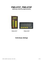
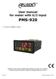
User manual - METER <strong>PMS</strong>-<strong>9<strong>20</strong></strong>/<strong>20</strong><br />
characteristic is displayed for about approx. 1.5 sec. After that device waits for<br />
selection of point being edited (by [^], [v] buttons). The short pressing of [ENTER]<br />
button causes by switching between X and Y value of the displayed point. The long<br />
press (press and hold at least 2 sec) of [ENTER] button causes by entering to edit<br />
the selected coordinate of the point. Modification of the coordinates is done<br />
accordingly to numerical parameters edition.<br />
i<br />
“AddP”, ”dELP” and “EdtP” options are available only if the user defined<br />
characteristic is used (it means when parameter “CHAr” = ”USEr”).<br />
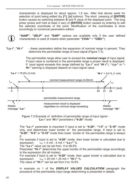
“Lo r”, ”Hi r”<br />
- these parameters define the expansion of nominal range in percent. They<br />
determine the permissible range of input signal (Figure 7.3).<br />
The permissible range allow user to exceed the nominal range of input signal.<br />
If input value is contained in the permissible range a proper result is displayed.<br />
If input signal exceeds this range (defined by “Lo r” and “Hi r”), “-Lo-” or “-<br />
Hi-” warning is displayed depend on input signal value.<br />
”Lo r” = 75,0% (3 mA)<br />
I min<br />
nominal measurement range (4-<strong>20</strong>mA)<br />
”Hi r” = 5,0 % (1 mA)<br />
I max<br />
0<br />
1<br />
4 <strong>20</strong> 21 22<br />
[mA]<br />
permissible measurement range<br />
display<br />
message ”-Lo-”<br />
measurement result is displayed<br />
regardless on nominal range exceeding<br />
display<br />
message ”-Hi-”<br />
Figure 7.3 Example of definition of permissible range of input signal -<br />
“Lo r” and “Hi r” parameters (“4-<strong>20</strong>” mode)<br />
The “Lo r” parameter is important if input is set to “4-<strong>20</strong>”, “1-5” or “2-10” mode<br />
only, and determines lower border of the permissible range. If input is set to<br />
“0-<strong>20</strong>”, “0-5” or “0-10” mode then lower border of the permissible range is always<br />
0.<br />
For example if input is set to “4-<strong>20</strong>” mode, then lower border is calculated due to<br />
expression: I min = 4 mA - 4 mA × “Lo r” %.<br />
The “Lo r” value can be set from 0 to 99.9%.<br />
Parameter “Hi r” determines the upper border of the permissible range accordingly<br />
to the expression (for all modes).<br />
For example if input is set to “4-<strong>20</strong>” mode, then upper border is calculated due to<br />
expression: I max = <strong>20</strong> mA + <strong>20</strong> mA × “Hi r” %.<br />
The value of “Hi r” can be set from 0 to 19.9%<br />
In example no 1 of the DISPLAY VALUES CALCULATION paragraph the<br />
procedure of the permissible input range determining is presented in details.<br />
30