PMS-920/20 - Aplisens
PMS-920/20 - Aplisens
PMS-920/20 - Aplisens

Create successful ePaper yourself
Turn your PDF publications into a flip-book with our unique Google optimized e-Paper software.
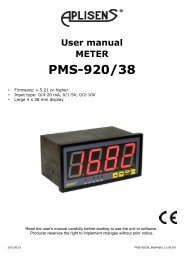
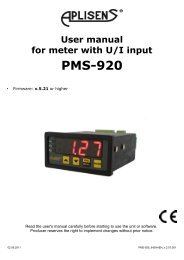
User manual - METER <strong>PMS</strong>-<strong>9<strong>20</strong></strong>/<strong>20</strong><br />
11. THE MODBUS PROTOCOL HANDLING<br />
Transmission parameters: 1 start bit, 8 data bits, 1 or 2 stop bit (2 bits are send, 1 and 2 bits<br />
are accepted when receive), no parity control<br />
Baud rate:<br />
selectable from: 1<strong>20</strong>0 to 115<strong>20</strong>0 bits/second<br />
Transmission protocol: MODBUS RTU compatible<br />
The device parameters and display value are available via RS-485 interface, as HOLDINGtype<br />
registers (numeric values are given in U2 code) of Modbus RTU protocol. The registers<br />
(or groups of the registers) can be read by 03h function, and wrote by 06h (single registers) or<br />
10h (group of the registers) accordingly to Modbus RTU specification. Maximum group size for<br />
03h and 10h functions can not exceeds 16 registers (for single frame).<br />
i<br />
The device interprets the broadcast messages, but then do not sends the answers.<br />
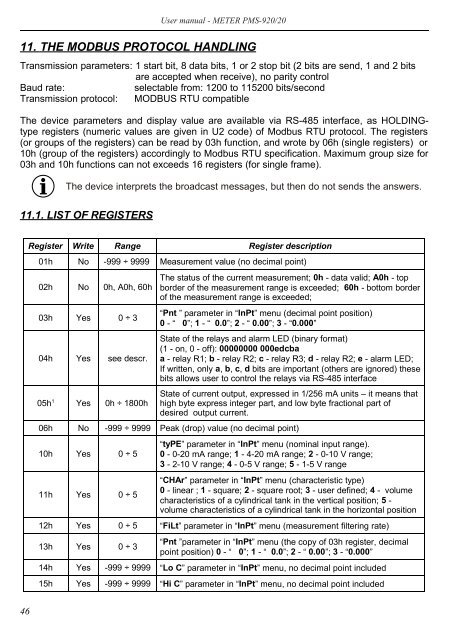
11.1. LIST OF REGISTERS<br />
Register Write Range Register description<br />
01h No -999 ÷ 9999 Measurement value (no decimal point)<br />
02h No 0h, A0h, 60h<br />
03h Yes 0 ÷ 3<br />
04h Yes see descr.<br />
05h 1 Yes 0h ÷ 1800h<br />
The status of the current measurement; 0h - data valid; A0h - top<br />
border of the measurement range is exceeded; 60h - bottom border<br />
of the measurement range is exceeded;<br />
“Pnt ” parameter in “InPt” menu (decimal point position)<br />
0 - “ 0”; 1 - “ 0.0”; 2 - “ 0.00”; 3 - “0.000”<br />
State of the relays and alarm LED (binary format)<br />
(1 - on, 0 - off): 00000000 000edcba<br />
a - relay R1; b - relay R2; c - relay R3; d - relay R2; e - alarm LED;<br />
If written, only a, b, c, d bits are important (others are ignored) these<br />
bits allows user to control the relays via RS-485 interface<br />
State of current output, expressed in 1/256 mA units – it means that<br />
high byte express integer part, and low byte fractional part of<br />
desired output current.<br />
06h No -999 ÷ 9999 Peak (drop) value (no decimal point)<br />
10h Yes 0 ÷ 5<br />
11h Yes 0 ÷ 5<br />
“tyPE” parameter in “InPt” menu (nominal input range).<br />
0 - 0-<strong>20</strong> mA range; 1 - 4-<strong>20</strong> mA range; 2 - 0-10 V range;<br />
3 - 2-10 V range; 4 - 0-5 V range; 5 - 1-5 V range<br />
“CHAr” parameter in “InPt” menu (characteristic type)<br />
0 - linear ; 1 - square; 2 - square root; 3 - user defined; 4 - volume<br />
characteristics of a cylindrical tank in the vertical position; 5 -<br />
volume characteristics of a cylindrical tank in the horizontal position<br />
12h Yes 0 ÷ 5 “FiLt” parameter in “InPt” menu (measurement filtering rate)<br />
13h Yes 0 ÷ 3<br />
“Pnt ”parameter in “InPt” menu (the copy of 03h register, decimal<br />
point position) 0 - “ 0”; 1 - “ 0.0”; 2 - “ 0.00”; 3 - “0.000”<br />
14h Yes -999 ÷ 9999 “Lo C” parameter in “InPt” menu, no decimal point included<br />
15h Yes -999 ÷ 9999 “Hi C” parameter in “InPt” menu, no decimal point included<br />
46