RP100 rack and pinion steering installation and ... - PYI Inc.
RP100 rack and pinion steering installation and ... - PYI Inc.
RP100 rack and pinion steering installation and ... - PYI Inc.

You also want an ePaper? Increase the reach of your titles
YUMPU automatically turns print PDFs into web optimized ePapers that Google loves.
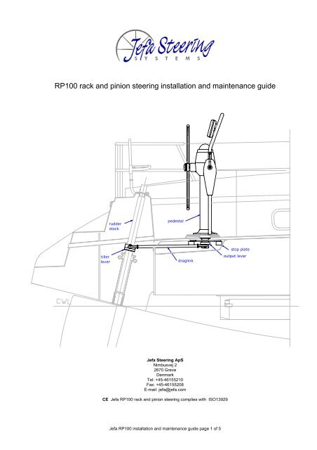
<strong>RP100</strong> <strong>rack</strong> <strong>and</strong> <strong>pinion</strong> <strong>steering</strong> <strong>installation</strong> <strong>and</strong> maintenance guide<br />
rudder<br />
stock<br />
pedestal<br />
tiller<br />
lever<br />
draglink<br />
stop plate<br />
output lever<br />
Jefa Steering ApS<br />
Nimbusvej 2<br />
2670 Greve<br />
Denmark<br />
Tel: +45-46155210<br />
Fax: +45-46155208<br />
E-mail: jefa@jefa.com<br />
CE Jefa <strong>RP100</strong> <strong>rack</strong> <strong>and</strong> <strong>pinion</strong> <strong>steering</strong> complies with ISO13929<br />
Jefa <strong>RP100</strong> <strong>installation</strong> <strong>and</strong> maintenance guide page 1 of 5
Jefa <strong>RP100</strong> <strong>rack</strong> <strong>and</strong> <strong>pinion</strong> <strong>steering</strong> <strong>installation</strong> guide<br />
Your Jefa <strong>steering</strong> RP-system has been designed <strong>and</strong> manufactured to the highest st<strong>and</strong>ards to provide<br />
many years of trouble free service. To aid you with the <strong>installation</strong> we have prepared these simple<br />
guidelines, which are vital to follow if the systems full potential <strong>and</strong> reliability are to be achieved. The notes<br />
should be read carefully before <strong>installation</strong> is commenced. Should you encounter any problems not covered<br />
in these instructions or have any queries please contact Jefa Steering or your local Jefa agent who will be<br />
pleased to provide technical guidance.<br />
Specification:<br />
Jefa <strong>steering</strong> <strong>RP100</strong> pedestal specifications:<br />
Maximum turns lock to lock 1.8<br />
St<strong>and</strong>ard output lever operating centres 130 mm.<br />
St<strong>and</strong>ard tiller lever operating centres 200 mm.<br />
Rated output force 12503 N.<br />
Maximum rudder torque at midschips 255 Kgf.m/2500Nm<br />
Maximum rudder torque at full lock 464 Kgf.m/4550Nm<br />
Installation – basic steps:<br />
Sight pedestal<br />
Reinforce cockpit floor if necessary<br />
Drill cockpit floor <strong>and</strong> fit pedestal<br />
Setting up the geometry<br />
Fit the tiller arm<br />
Fit rudder stops or stop plate<br />
Install draglink<br />
Test system<br />
Sighting the pedestal<br />
The pedestal should be installed in a position<br />
where there is adequate space to fully control the<br />
craft at all times whilst providing sufficient shelter<br />
for the helmsman to brace himself in severe sea<br />
conditions. Care should be taken to ensure that it<br />
will not obstruct members of the crew from<br />
operating bilge pumps, sheet winches <strong>and</strong> cockpit<br />
locker lids, etc. Alternatively these items may<br />
require repositioning. Where the pedestal is<br />
situated near the mainsheet a guard should always<br />
be fitted to help prevent the sheet snagging the<br />
pedestal in an inadvertent gybe. The optimum<br />
position for mounting the pedestal relative to a<br />
helmsman’s seat is shown in the right figure. Next<br />
check that there is sufficient clearance below the<br />
cockpit floor to allow the output lever to move<br />
freely <strong>and</strong> for the draglink to operate. The draglink<br />
should operate horizontally ± 5° <strong>and</strong> the rudder<br />
stock should next be examined to ensure that the<br />
tiller arm can be fitted at the correct height.<br />
Reinforcement of the cockpit floor<br />
The cockpit sole must be sufficient rigid to withst<strong>and</strong> the <strong>steering</strong> loads or the force of the helmsman thrown<br />
onto the wheel in severe sea conditions without deflecting significantly. As a guideline for GRP boats, the<br />
cockpit floor should have a total thickness of at least 40 mm.<br />
Jefa <strong>RP100</strong> <strong>installation</strong> <strong>and</strong> maintenance guide page 2 of 5
Drilling of the cockpit floor <strong>and</strong> the fitting of the pedestal<br />
248<br />
220<br />
120<br />
After finding the correct pedestal position in the cockpit the cockpit floor can be<br />
drilled according to the right figure. The holes for the mounting bolts should be<br />
drilled to 10.5 mm.<br />
Remove the output lever from the down shaft. Put the pedestal on place <strong>and</strong><br />
attach the wheel. Carefully measure to both ship centrelines if the pedestal is<br />
positioned correctly. Use a sealant to seal off the pedestal.<br />
Ø10<br />
Setting up the geometry<br />
Before commencing to fit the output lever <strong>and</strong> tiller arm it is important to underst<strong>and</strong> about the offset angles<br />
used with the <strong>rack</strong> <strong>and</strong> <strong>pinion</strong> system. The <strong>rack</strong> <strong>and</strong> <strong>pinion</strong> systems uses a principal known as “wide angle<br />
geometry” which gives very direct <strong>steering</strong> near amidships <strong>and</strong> an increasing mechanical advantage as the<br />
rudder approaches full travel. This results in the most direct, positive system available to a helmsman.<br />
To accomplish this effect the pedestal output lever is shorter than the tiller lever in a ratio of 1.54:1. At<br />
amidships therefore the tiller arm <strong>and</strong> output lever are not pointing 90 degrees sideways, but instead are<br />
angled slightly forward. This offset angle is known as B° <strong>and</strong> varies dependent on the distance between the<br />
pedestal <strong>and</strong> the rudderstock. The shorter the distance the greater the offset angle B.<br />
L3<br />
64°<br />
B°<br />
B°<br />
36°<br />
36°<br />
In the table below we show the pedestal to rudder stock distance L3 <strong>and</strong> the corresponding offset angle B°.<br />
If you have instructed us to finish bore <strong>and</strong> key the tiller arm we will have checked the distance L3 <strong>and</strong> cut<br />
the key-way in the tiller arm to the correct offset angle.<br />
L3 mm B°<br />
(distance between pedestal<br />
(lever offset angle forward)<br />
centre <strong>and</strong> rudder stock)<br />
less than 200 mm<br />
refer to factory-custom<br />
200-275 25°<br />
276-350 20°<br />
351-450 15°<br />
451-550 12°<br />
551-650 10°<br />
651-1000 8°<br />
1000-> 5°<br />
Jefa <strong>RP100</strong> <strong>installation</strong> <strong>and</strong> maintenance guide page 3 of 5
Please note the above assumes the pedestal is mounted forward of the rudder stock. If the pedestal is<br />
mounted behind the rudder stock the same offset angles apply but the levers are offset aft. (a good<br />
reminder is the fact that the levers, with the rudder amidships, will always point away from the rudder shaft<br />
in the pedestal direction)<br />
Fitting the tiller arm<br />
The tiller arm should always have a perfect fit to the rudder shaft. Between the two till arm parts there<br />
should always be a gap to make sure the tiller arm can be clamped. The tiller arm should be slided in<br />
vertical direction to achieve the best possible horizontal run of the draglink. The angle of the draglink should<br />
not exceed 5° to the horizon.<br />
The tiller arm should be firmly locked for rotation around the rudder shaft. Never use just clamping to<br />
achieve this rotation locking. The best rotational locking is achieved by a keyway in the shaft <strong>and</strong> lever<br />
combined with a stainless steel key. The keyway in the shaft should be machined 90° starboard (or port,<br />
depending on the lever positions) The keyway in the tiller lever should be machined in the offset angle B.<br />
The torque for the 4 mounting bolts of the tiller lever is 45 Nm. Tubular rudder stocks <strong>and</strong> carbon rudder<br />
stocks should use a through bolt to achieve a proper rotational locking.<br />
Fitting rudder stops or stop plate<br />
View of RP stop plate from inside the ship looking up to<br />
the pedestal with the lever mounted on starboard.<br />
The Jefa <strong>rack</strong> <strong>and</strong> <strong>pinion</strong> system should always be<br />
delivered with the stop plate. The stop plate will<br />
prevent the output lever from going over the dead<br />
point. If this happens, the yacht will not be able to<br />
steer any more with all due consequences. The<br />
stop plate will prevent the <strong>steering</strong> pedestal from<br />
damage, but when no rudder stops are fitted, all<br />
forces will have to go thought the draglink <strong>and</strong> in<br />
the prevent of a collision, the draglink could get<br />
damaged. Fitting rudder stops in combination with<br />
the stop plate will protect both the pedestal <strong>and</strong><br />
the rudder.<br />
On a starboard run <strong>installation</strong>, the stop plate<br />
should be fitted with the text <strong>and</strong> arrow pointing<br />
downwards (readable). On port run <strong>installation</strong>s,<br />
the text has to market over to the other side with a<br />
marker pen <strong>and</strong> the two stop blocks should be<br />
positioned in the opposite side of the tap holes.<br />
The arrow on the stop plate should always point<br />
away from the rudder shaft. Normally this will be<br />
the bow of the yacht. When the rudder stock is in<br />
front of the pedestal, the arrow has to point aft.<br />
Look in the above table to find the appropriate<br />
offset angle for the <strong>installation</strong>. Rotate the stop<br />
plate so the mounting bolt matches the angle of<br />
the table. Firmly tighten the mounting bolts so the stop plate will not rotate under load. Put the output lever<br />
in the correct offset angle <strong>and</strong> height. A help is to put a straight bar against the stop blocks <strong>and</strong> put the<br />
output lever 90 degrees to the bar. Now tighten the friction brake in the pedestal so the output lever stays in<br />
this position. Slide the output lever upwards as far as possible with 5 mm clearance between the mounting<br />
nuts <strong>and</strong> the top of the output lever. This will make sure the output lever hits the stop blocks properly <strong>and</strong><br />
will not slide over.<br />
Fitting the draglink.<br />
Make sure the rudder is in the exact amidships position <strong>and</strong> lock it. Carefully measure the distance between<br />
the two pin centres. Rotate the rose joints of the draglink to achieve the correct length <strong>and</strong> lock them with<br />
the locking nut. Slide both sides over the pin <strong>and</strong> tighten the lever bolts correctly.<br />
Jefa <strong>RP100</strong> <strong>installation</strong> <strong>and</strong> maintenance guide page 4 of 5
Fitting the engine control mechanism <strong>and</strong> housing (optional)<br />
The Jefa <strong>RP100</strong> system can be fitted with an optional TFX engine control<br />
mechanism. For the ease of mounting the engine control cables (not included),<br />
dismount the mechanism by unscrewing bolts with number 1. Follow the<br />
instructions in the accompanying TFX <strong>installation</strong> manual. Reinstall the<br />
mechanism with the attached cables back in the mounting b<strong>rack</strong>et <strong>and</strong> tighten<br />
bolts 1 again. Make sure the bottom tube ends at least 5 mm above the bottom<br />
b<strong>rack</strong>et (see position 3). Put both cover parts in place <strong>and</strong> carefully tighten the<br />
4 off 4.2 x 9 mm self tapping screws (position 2). Don’t over tighten these<br />
screws as it will damage the housing. Mount the Jefa stainless steel engine<br />
control h<strong>and</strong>le. Make sure the h<strong>and</strong>le reaches the end of the splined shaft.<br />
Carefully hit it with a rubber hammer if necessary. Tighten the 2 set screws at<br />
the bottom of the h<strong>and</strong>le. Check in the machine room if both the throttle <strong>and</strong><br />
gearbox levers reach the outer positions <strong>and</strong> if they are set up correctly in the<br />
neutral position. With the red push button one can disengage the gearbox <strong>and</strong><br />
operate the throttle independently for starting up the engine.<br />
Test the system<br />
Ask a colleague to slowly turn the wheel from lock to lock <strong>and</strong> check that:<br />
• The tiller arm reaches the rudder stops (if fitted) just before or at the same time as the output lever<br />
hits the stop plate blocks.<br />
• The draglink does not foul on the boat structure.<br />
• The rose joints do not exceed their designed working angle <strong>and</strong> bind.<br />
• The rudder has an equal rudder travel of 36 degrees both ways.<br />
If the above points check out O.K. then ask a colleague to apply moderate load (20 Kg on the rim) with the<br />
tiller up against each rudder stop <strong>and</strong> check that the stops <strong>and</strong> the cockpit floor do not flex significantly.<br />
The basic <strong>installation</strong> of the Jefa <strong>rack</strong> <strong>and</strong> <strong>pinion</strong> system is now complete.<br />
We hope you enjoy your Jefa <strong>rack</strong> <strong>and</strong> <strong>pinion</strong> system – the finest system afloat!<br />
Maintenance hints<br />
Your Jefa <strong>steering</strong> <strong>rack</strong> <strong>and</strong> <strong>pinion</strong> system has been designed <strong>and</strong> manufactured to the highest st<strong>and</strong>ards to<br />
provide many years of trouble free service. To get the best from your system there are some simple<br />
maintenance hints:<br />
• At least twice a season thoroughly clean the pedestal in fresh water <strong>and</strong> apply a coat of good<br />
quality car wax polish.<br />
• If any paint has accidentally chipped, immediately rub down the area using a fine grade of wet <strong>and</strong><br />
dry abrasive <strong>and</strong> touch in with yacht enamel designed for aluminium surfaces. (RAL colour 9010).<br />
• Periodically check that the pedestal bolts, output lever bolts, draglink bolts <strong>and</strong> the tiller lever bolts<br />
are securely fastened.<br />
• Check that the system has proper rudder stops or a stop plate fitted.<br />
• Depending on the time used, the delrin balls in the rose joints could ware. These balls are easy to<br />
replace by rotating them 90 degrees <strong>and</strong> pushing them out. Replacement balls are available with<br />
part number DLB16.<br />
This is version 1.0 of the Jefa <strong>steering</strong> <strong>rack</strong> <strong>and</strong> <strong>pinion</strong> <strong>installation</strong> <strong>and</strong> maintenance manual, updates may<br />
be available at our online web catalogue www.jefa.com in the maintenance section.<br />
Jefa <strong>RP100</strong> <strong>installation</strong> <strong>and</strong> maintenance guide page 5 of 5