Isolating switching repeater TS-500 Ex
Isolating switching repeater TS-500 Ex
Isolating switching repeater TS-500 Ex

You also want an ePaper? Increase the reach of your titles
YUMPU automatically turns print PDFs into web optimized ePapers that Google loves.
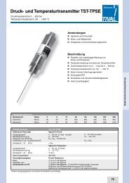
<strong>Isolating</strong> <strong>switching</strong> <strong>repeater</strong> <strong>TS</strong>-<strong>500</strong> <strong>Ex</strong><br />
1- and 2-channel device<br />
Features<br />
n Input for <strong>switching</strong> contact, proximity switch<br />
Namur type acc. to DIN EN 60947-5-6 or<br />
opto-coupler<br />
n Input intrinsically safe acc to:<br />
ATEX II (1) G [<strong>Ex</strong> ia] IIC/IIB<br />
ATEX II (1) D [<strong>Ex</strong> iaD]<br />
n Switchable line fault detection<br />
for broken and shorted lines<br />
n Output relay SPDT contact or<br />
electronic (transistor passive) available<br />
n Supply voltage 230 V AC or 24 V DC<br />
n Power on LED, status / error LED<br />
n 22.5 mm case for DIN rail mounting<br />
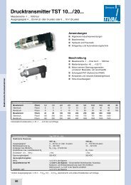
<strong>Isolating</strong> switch-coupler <strong>TS</strong>-<strong>500</strong> <strong>Ex</strong> can be used for<br />
monitoring and controlling digital signals out of the<br />
hazardous area. The intrinsically safe input is suitable<br />
for <strong>switching</strong> contact, proximity switch acc. Namur DIN<br />
EN 60947-5-6), or passive electronic outputs of other<br />
devices. The devices must be installed out of the<br />
<strong>Ex</strong>-area, because only the input is intrinsically safe.<br />
Controls and accessories<br />
Ordering code<br />
1 Type <strong>TS</strong>-<strong>500</strong> <strong>Ex</strong> ia<br />
(categoric „ia“ includes „ib“)<br />
2 Output<br />
n 1R = 1-channel with relay output<br />
n 2R = 2-channel with relay output<br />
n 1T = 1-channel with electronic output<br />
n 2T = 2-channel with electronic output<br />
3 Supply voltage<br />
n 0 = 230 V AC ± 10 %<br />
n 5 = 24 V DC ± 15 %<br />
50 ... 60 Hz<br />
Requirements<br />
n It is necessary to keep the conditions of the<br />
ATEX EC-Type examination certificate.<br />
n The device must be installed in dry and<br />
good monitored rooms.<br />
n If the intrinsinc safety input is connected to the<br />
dust endangered area of zone 20 or 21, it has<br />
to be ensured that the corresponding devices<br />
in this circuit have the requirements of category<br />
1D or 2D.<br />
n Reparing and design modifications may only be<br />
carried out by the manufacturer.<br />
<strong>Ex</strong>ample:<br />
1 2 3<br />
<strong>TS</strong>-<strong>500</strong> <strong>Ex</strong> ia - 1R - 0<br />
<strong>TS</strong>-<strong>500</strong> <strong>Ex</strong> ia-1R-0<br />
169
<strong>Isolating</strong> <strong>switching</strong> <strong>repeater</strong> <strong>TS</strong>-<strong>500</strong> <strong>Ex</strong><br />
1- and 2-channel device<br />
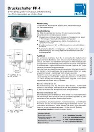
Controls and accessories<br />
Technical data<br />
Type: <strong>TS</strong>-<strong>500</strong> <strong>Ex</strong><br />
<strong>Ex</strong>plosion protection<br />
Certification DMT 99 ATEX E 079<br />
Approval II (1) G [<strong>Ex</strong> ia] IIC/IIB or II (1) D [<strong>Ex</strong> iaD]<br />
Max. voltage (no load) U 0<br />
10,6 V<br />
Max. short cirduit current I 0<br />
26,8 mA<br />
Max. power consumption P 0<br />
71,0 mW<br />
(characteristic linear)<br />
Input classification<br />
ia / IIB ia / IIC<br />
Max. external capacity<br />
16,2 μF 2,3 μF<br />
Max. external inductivity<br />
110,0 mH 20,0 mH<br />
Internal capacity<br />
Internal inductivity<br />
negligible<br />
36 μH<br />
Power supply<br />
Supply voltage<br />
230 V AC± 10 % AC, 47 ... 63 Hz<br />
24 V DC ± 15 % (safety voltage 253 V AC / 125 V DC)<br />
Power consumption<br />
< 2 W<br />
Operating temperature<br />
-10 ... +55° C<br />
Rated voltage<br />
400 V AC acc. VDE0110 group 2 between input / output / supply voltage<br />
Test voltage<br />
4 kV DC between input / output / supply voltage<br />
conformity<br />
ATEX-directive 94/9/EG,<br />
EN 60079-0:2006 EN 60079-11:2007<br />
EN 61241-0:2006 EN 61241-11:2007<br />
IEC 61000-4-2/3/4/5/6/8/11<br />
Inputs (intrinsically safe)<br />
No load voltage<br />
Short circuit current<br />
Switching point<br />
Broken line detection<br />
Shorted line detection<br />
Output (relay)<br />
Switching capacity<br />
Max. <strong>switching</strong> frequency<br />
Max. <strong>switching</strong> delay<br />
Electronic output (transistor passive)<br />
Max. voltage<br />
Max. current<br />
Voltage drop<br />
Max. <strong>switching</strong> frequency<br />
Max. <strong>switching</strong> delay<br />
Case<br />
Weight<br />
Protection<br />
Connection<br />
approx. 8 V (acc. to DIN EN 60947-5-6, Namur)<br />
approx. 8 mA (acc. to DIN EN 60947-5-6, Namur)<br />
inactive ≤ 1,2 mA, aktiv ≥ 2,1 mA, Hysterese ca. 0,5 mA<br />
≤ 0,1 mA<br />
≥ 7,5 mA<br />
< 253 V AC < 100 VA < 2 A; < 100 V DC < 50 W < 2 A<br />
5 Hz<br />
20 ms (2-channel: 50 ms)<br />
35 V DC (safety voltage 253 V AC / 125 V DC)<br />
50 mA (short circuit proof)<br />
≤ 3,5 V (at load 50 mA)<br />
2 kHz (50 % keying ratio)<br />
300 μs<br />
standard case of polycarbonate 8020 UL94V-1<br />
acc. to DIN EN 60715:2001-09<br />
~ 200 g<br />
case IP30, terminals IP20 finger safe acc. to German BGV A3<br />
screw terminal with pressure plate, max. 2.5 mm², wire<br />
Panel controls<br />
170
<strong>Isolating</strong> <strong>switching</strong> <strong>repeater</strong> <strong>TS</strong>-<strong>500</strong> <strong>Ex</strong><br />
1- and 2-channel device<br />
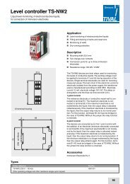
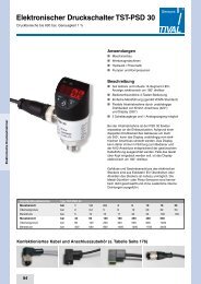
Connection diagram<br />
Controls and accessories<br />
Dimensional drawing and controls (narrow side)<br />
171