operation / maintenance manual
operation / maintenance manual
operation / maintenance manual

You also want an ePaper? Increase the reach of your titles
YUMPU automatically turns print PDFs into web optimized ePapers that Google loves.
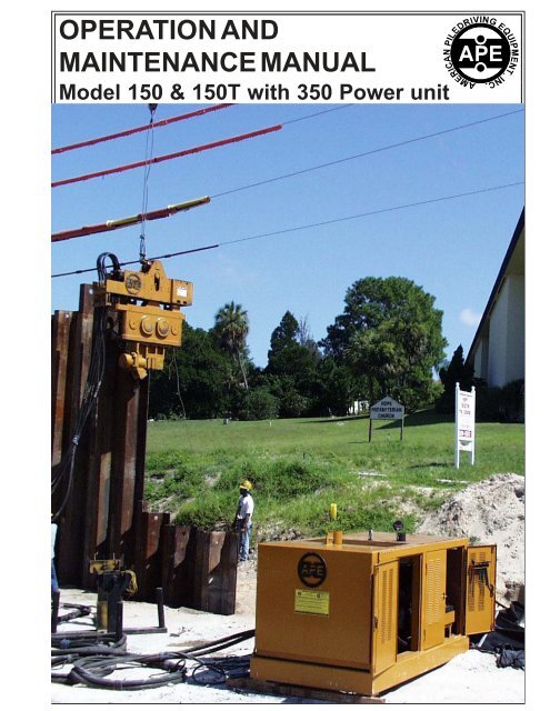
OPERATION AND<br />
MAINTENANCE MANUAL<br />
OPERATION / MAINTENANCE MANUAL<br />
MODEL 150/150T VIBRATORY DRIVER WITH MODEL 330/525 POWER UNIT<br />
7032 SOUTH 196th - KENT, WA. 98032 - (253) 872-0141 / FAX (253) 872-8710<br />
Model 150 & 150T with 350 Power unit
OPERATION / MAINTENANCE MANUAL<br />
MODEL 150/150T VIBRATORY DRIVER WITH MODEL 330/525 POWER UNIT<br />
7032 SOUTH 196th - KENT, WA. 98032 - (253) 872-0141 / FAX (253) 872-8710
OPERATION / MAINTENANCE MANUAL<br />
MODEL 150/150T VIBRATORY DRIVER WITH MODEL 330/525 POWER UNIT<br />
7032 SOUTH 196th - KENT, WA. 98032 - (253) 872-0141 / FAX (253) 872-8710<br />
General Safety Precautions<br />
(This list of precautions must be followed at all times to ensure personal & equipment safety.)<br />
1. Read this <strong>manual</strong> from beginning to end before operating or working on this machine.<br />
2. When operating in a closed area, pipe exhaust fumes outside. (WARNING: Breathing<br />
exhaust fumes can cause serious injury and even death.)<br />
3. When servicing batteries, avoid any type of spark or open flame. Batteries generate explosive<br />
gases during charging. There must be proper ventilation when charging batteries.<br />
4. Never Adjust or repair the unit while it is in <strong>operation</strong>.<br />
5. Make sure the Control Pendant is in the "OFF" position before starting the unit.<br />
6. Remove all tools and electrical cords before starting the unit.<br />
7. Keep oily rags away from the exhaust system.<br />
8. Never store flammable liquids near the engine.<br />
9. Never stand under vibro at any time and keep your eyes on the vibro when it is in <strong>operation</strong>.<br />
Keep a look out for loose bolts or leaking hydraulic lines.<br />
10. Avoid pulling on hose quick dis-connect fittings. Move power unit closer to work if hoses cannot<br />
reach. Do not use hoses as a tow line to tug the power unit! If a hose fails at the hydraulic couplers<br />
then it is a result of "hose tugging by the pile crew".<br />
11. Avoid kinks in the hoses. Kinks will cut the hose safety factor by 50 percent.<br />
12. Always wear eye and ear protection.<br />
13. Avoid standing downwind of vibrating piles. Dirt and other matter may become airborne and fall<br />
into the unprotected eye.<br />
14. Always wear a hard hat, gloves, and safety shoes.<br />
15. Always attach safety line to pile when extracting or hoisting into position.<br />
16. (WARNING) Never clamp vibro to pile and dis-connect from crane line. Lay vibro down on<br />
ground when not in use.<br />
17. Do not truck power unit with quick disconnect caps and plugs screwed on to fittings unless the<br />
caps and plugs have wire rope safety lines attached. Store in storage box under control panel.<br />
18. Keep fingers and hands away from machine at all times. Tie ropes to machine to aid in turning or placing equipment.<br />
19. Never get between the forklift and the load. Vibro or power unit could shift on forks and crush you between the fork<br />
carriage and the load.<br />
20. Stand in a place that keeps the sun out of your eyes.<br />
Go to www.apevibro.com for addition information on this and other machines. In addition, please go through the online<br />
courses available on our website.
OPERATION / MAINTENANCE MANUAL<br />
MODEL 150/150T VIBRATORY DRIVER WITH MODEL 330/525 POWER UNIT<br />
7032 SOUTH 196th - KENT, WA. 98032 - (253) 872-0141 / FAX (253) 872-8710<br />
General Description of the Vibratory Pile Driver/Extractor<br />
The APE Vibro is a variable frequency vibratory pile driver/extractor designed to drive and extract all<br />
types of piles including sheet, pipe, timber, concrete, H-beam, I-beam and steel plates. This machine<br />
can also be used to dirve well casings, install wick drains, sand drains, and with special precautions<br />
approved by APE engineers, it can be used to compact soil.<br />
The three major parts to the Vibrator are as follows:<br />
A.) The Suppressor housing.<br />
B.) The Gearbox.<br />
C.) The Clamping Attachment.<br />
Note: The standard suppressor can be removed and replaced with a shorter suppressor to reduce<br />
overall height where headroom is limited. The clamp attachment is detachable to allow the machine to<br />
be fitted with special attachments for varying types of piles such as wood pile or pipe piles. Special<br />
clamping attachments can be made to fit any pile type.<br />
SUPPRESSOR<br />
HOUSING<br />
GEARBOX<br />
CLAMP ATTACHMENT<br />
(shown with sheet clamp)<br />
Page 1-3
123456789012345678901234567890121<br />
123456789012345678901234567890121<br />
123456789012345678901234567890121<br />
123456789012345678901234567890121<br />
123456789012345678901234567890121<br />
123456789012345678901234567890121<br />
123456789012345678901234567890121<br />
123456789012345678901234567890121<br />
123456789012345678901234567890121<br />
123456789012345678901234567890121<br />
123456789012345678901234567890121<br />
123456789012345678901234567890121<br />
123456789012345678901234567890121<br />
123456789012345678901234567890121<br />
123456789012345678901234567890121<br />
123456789012345678901234567890121<br />
OPERATION / MAINTENANCE MANUAL<br />
MODEL 150/150T VIBRATORY DRIVER WITH MODEL 330/525 POWER UNIT<br />
7032 SOUTH 196th - KENT, WA. 98032 - (253) 872-0141 / FAX (253) 872-8710<br />
The Suppressor Housing<br />
The suppressor housing of the APE 150 series is a patented multi-stage system consisting of two<br />
large rubber elastomers and eight small elastomers. The large rubber elastomers (technically called<br />
the first stage) are used during all driving <strong>operation</strong>s and light to medium extraction. The second stage<br />
is made up of eight small high capacity elastomers that do not engage until the crane has pulled<br />
approximately 10 tons of line pull. A large safety pin fitted inside a view slot indicates total line pull in<br />
tons. The safety pin travels down in the view slot during the extraction process. One inch of travel is equal<br />
to eight tons of line pull. ( WARNING! Hard pulling for long periods of time will heat and damage<br />
the large elastomers. The heat generated from constant heavy line pull will destroy the<br />
chemical bond between the rubber and mounting plate which will cause elastomer failure.)<br />
When engaged in hard extracting, break every 15 minutes to allow elastomers to cool.<br />
The safety pin moves down to the bottom of the slot<br />
when pulling. One inch of travel equals 8 tons of line pull<br />
for a maximum of ten inches or 80 tons. When pin<br />
reaches the bottom of the slot the suppressor has 80<br />
tons of line pull on it. Do not pull beyond that point.<br />
Lifting Shackle<br />
Large Elastomer<br />
Small Elastomer<br />
Suppressor<br />
Housing<br />
Safety Pin<br />
Center Plate<br />
Top Plate<br />
Page 1-4
123456789012<br />
123456789012<br />
123456789012<br />
123456789012<br />
123456789012<br />
123456789012<br />
123456789012<br />
123456789012<br />
123456789012<br />
123456789012<br />
123456789012<br />
123456789012<br />
123456789012<br />
123456789012<br />
123456789012<br />
123456789012<br />
OPERATION / MAINTENANCE MANUAL<br />
MODEL 150/150T VIBRATORY DRIVER WITH MODEL 330/525 POWER UNIT<br />
7032 SOUTH 196th - KENT, WA. 98032 - (253) 872-0141 / FAX (253) 872-8710<br />
The Vibrator Gearbox<br />
The vibrator gearbox contains two rotatingjohnw eccentric weights cast in one piece with the gear. This<br />
design is unique to the industry and was developed by the engineers of APE to solve a number of<br />
problems associated with other types of vibrator machines. Both the eccentric and the drive gears have<br />
been helically cut to provide high speed <strong>operation</strong> with reduced noise and wear. Vibration is caused<br />
by the vertical movement created when the eccentrics are rotated. The eccentric and drive gears are<br />
all driven in line by two Volvo or Rexroth 125 motors tucked in on the outboard side of the gearbox. The<br />
motors are recessed for maximum protection. The eccentrics rotate on two shafts housed by four giant<br />
spherical bearings. The gears and bearings receive lubrication as a result of the fluid splashing inside<br />
the gearbox when the gears are rotated. The oil level is quickly determined by looking at the site gauge.<br />
The Model 150/150T can be operated under water to a depth of 30 feet without modifications. (Consult<br />
factory for depths below 30 feet.)<br />
Rifle Bored Top Plate<br />
Hydraulic Motor<br />
Bearing Cover<br />
Oil<br />
Level<br />
123456789012<br />
Use Mobil SCH 629<br />
GLASS SIGHT GAUGE<br />
Note: Please check the oil level before operating the vibro. Check when the machine is stopped and make sure you wait at least 60<br />
seconds for the oil splash to settle to the bottom of the gearbox so that you get an accurate reading. Check this level throughout the day to<br />
make sure there are no leaks. The oil level may raise rapidly if the hydraulic motor experiences a shaft seal failure which can pump<br />
hydraulic oil into the gearbox. An overfilled gearbox will create massive heat that will destroy the bearings.<br />
Note: When experiencing hard driving or extracting the oil may overheat due to overuse of the machine. When driving or extracting in<br />
difficult soil conditions, use a heat gun to monitor the temperature of the gearbox. The oil must be changed if the oil temperature becomes<br />
black or burnt. Overheated oil looses its lubricating ability and cause metal to metal contact on the bearings and other moving parts resulitng<br />
in Page premature 1-5 bearing and gear failure. Change the oil if you think it has been overheated. When driving or extracting underwater please<br />
make sure the bearing cover o-rings are in excellent condition and that all plugs are sealed and the bolts are tight on the top plate. Consult<br />
the factory for additional instructions for underwater <strong>operation</strong>s beyond 30 feet of depth.
OPERATION / MAINTENANCE MANUAL<br />
MODEL 150/150T VIBRATORY DRIVER WITH MODEL 330/525 POWER UNIT<br />
7032 SOUTH 196th - KENT, WA. 98032 - (253) 872-0141 / FAX (253) 872-8710<br />
The Clamp Attachment<br />
GENERAL INFORMATION (Continued...)<br />
The APE vibrator comes with a standard sheet pile clamp attachment. The clamp contains two<br />
gripping jaws. One is "fixed" and one is "moveable". A large hydraulic cylinder operates the moveable<br />
jaw with up to 250 tons of clamping force depending on clamp pump relief pressure. The jaws open and<br />
close by turning a switch on the remote control pendant or may be operated by turning the switch at the<br />
main control panel mounted behind one of the doors on the power unit. The valve can be <strong>manual</strong>ly<br />
operated with a screwdriver if all electrical fails. The APE standard sheet pile clamp can be fitted with<br />
jaws to fit many different types of piles including sheet piles, H-Beams, steel plates, steel rods, pipe<br />
piles, wood piles, and concrete piles. (Contact APE or your local APE distributor for more information<br />
on clamp attachments for special pile types or visit us at www.apevibro.com)<br />
Clamp Attachment<br />
Fixed Jaw<br />
Moveable Jaw<br />
Clamp Cylinder<br />
Pile Guide<br />
The Clamp Attachment Bolt Pattern Configuration<br />
Notice: If you are involved in changing a<br />
clamp attachment then please train your crew<br />
to clean the machined surfaces of both the<br />
bottom of the vibro and the top of the clamp so<br />
that when they bolt the two together they will<br />
mate up properly. Sometimes a crew will<br />
forget to do this and the dirt or dent in the<br />
metal surface will prevent the bolts from<br />
becoming fully tight. When this happens, the<br />
clamps bolts break. If a bolt breaks, it is a<br />
direct result of a sloppy mechanic that failed<br />
to use common sense when installing a clamp<br />
attachment. If one bolt breaks, replace them<br />
all.<br />
Page 1-6
OPERATION / MAINTENANCE MANUAL<br />
MODEL 150/150T VIBRATORY DRIVER WITH MODEL 330/525 POWER UNIT<br />
7032 SOUTH 196th - KENT, WA. 98032 - (253) 872-0141 / FAX (253) 872-8710<br />
Optional Attachments<br />
The following are some of the optional attachments for the Vibratory hammer. APE attachments will fit<br />
ICE and MKT machines. Go to www.apevibro.com for more details on clamp attachments.<br />
(Contact APE or your local APE distributor for more information about these and other available equipment.)<br />
7 ft. Caisson Beam (#901000)<br />
8 ft. Caisson Beam (#902000)<br />
11ft.Caisson Beam (#903000)<br />
Caisson Clamp (#250000)<br />
APE CAISSON CLAMP<br />
90 Degree Adapter<br />
Plate (#905000)<br />
4 ft. Extension Adapter<br />
(#906000)<br />
Clamp Attachment<br />
APE 90 DEGREE<br />
ADAPTER WITH EXTENSION<br />
APE DELUXE WOOD CLAMP<br />
(#907000)<br />
Page 1-7
OPERATION / MAINTENANCE MANUAL<br />
MODEL 150/150T VIBRATORY DRIVER WITH MODEL 330/525 POWER UNIT<br />
7032 SOUTH 196th - KENT, WA. 98032 - (253) 872-0141 / FAX (253) 872-8710<br />
General Description of Model 350 Power Unit<br />
The 150/150T vibrator runs off the APE 350 power unit. The APE 350 has a CAT C-9 with 350<br />
horsepower engine. Optional engines are available. The engine is mounted to a tubular frame that also<br />
serves as a diesel fuel tank. A sheet metal and tube frame covers the engine and is equipped with<br />
locking doors for protection from the environment. A control panel is located behind one of the doors<br />
and comes complete with a 50 foot control pendant. There are two hydraulic tanks on the power unit.<br />
One is the main tank and the other is a storage tank for extra oil in case the main tank becomes depleted.<br />
A hydraulic tank supplies oil to four pumps. Fixed displacement pumps feed the two vibrator motors.<br />
A small pump feeds the clamp attachment and another feeds the cooling circuit. The Vibrator is<br />
connected to the power unit via five hydraulic hoses. The two large hoses are the pressure and return<br />
lines for the vibrator motors. The two small hoses are for the clamp system and the one odd hose is for<br />
the vibrator motor case drain line. The hoses are attached to the power unit by connecting the "quick<br />
disconnect fittings" on the end of the hoses leading from the vibrator. There is a special disconnect used<br />
only when operating a drill and the purpose of this connection is to shift the two-speed valve. The fittings<br />
go on only one way so there is no chance of hooking up the hoses backwards.<br />
WARNING: Clean with ether or a clean rag before installing quick disconnects. Make sure you<br />
seat the quick disconnect fittings all the way tight. Failure to tighten the quick disconnects will<br />
stop the flow of oil and will prevent the vibro from operating. Failure to tighten the clamp fittings<br />
completely tight will cause the jaws to either not open or not close. If this happens you may have<br />
to crack the fitting and bleed off the pressure to release the quick disconnects.<br />
Tube Frame<br />
Exhaust<br />
Muffler<br />
Lifting Eye<br />
Hydraulic Tank<br />
Quick Disconnect<br />
Fittings<br />
Fuel Tank<br />
Locking Doors<br />
Radiator<br />
Page 1-8
OPERATION / MAINTENANCE MANUAL<br />
MODEL 150/150T VIBRATORY DRIVER WITH MODEL 330/525 POWER UNIT<br />
7032 SOUTH 196th - KENT, WA. 98032 - (253) 872-0141 / FAX (253) 872-8710<br />
Vibratory Pile Driver/Extractor Parts Description- Suppressor Housing:<br />
Page 2-1A
OPERATION / MAINTENANCE MANUAL<br />
MODEL 150/150T VIBRATORY DRIVER WITH MODEL 330/525 POWER UNIT<br />
7032 SOUTH 196th - KENT, WA. 98032 - (253) 872-0141 / FAX (253) 872-8710<br />
Vibratory Pile Driver/Extractor Parts Description- Suppressor Housing:<br />
APE Model 150 Suppressor Parts List<br />
ITEM QTY DESCRIPTION PART #<br />
1 1 Outer Suppressor Housing 320102<br />
2 2 Loop Over Hose - Motor 421032<br />
3 1 Loop Over Hose - Case Drain 421003<br />
4 2 Loop Over Hose - Clamp 421004<br />
5 2 Hydraulic Flange Coupler 122012<br />
6 4 Flange O-Ring (2-226) 222010<br />
7 1 #12 SAE x #12 JIC Fitting 321011<br />
8 2 #8 SAE x #8 JIC Fitting 321012<br />
9 1 Check Valve Housing 321015<br />
10 1 Check Valve Cartridge 321016<br />
11 1 Pop-Off Valve 321009<br />
12 3 Bolt-SHCS 3/4" NC x 6-1/2" 124000<br />
13 3 3/4" Nylock Nut 124000<br />
14 16 Bolt-SHCS 5/8" x 2-1/4" 124000<br />
15 16 Lock Washer 5/8" High Collar 124000<br />
16 2 Pig Tail Hose - Clamp 421004<br />
17 1 Pig Tail Hose - Case Drain 421003<br />
18 2 Pig Tail Hose - Motor 421007<br />
19 1 Inner Suppressor 123015<br />
20 30 Bolt-SHCS 3/4" NC x 6" 124000<br />
21 50 Lock Washer 3/4" High Collar 124000<br />
22 40 Bolt-SHCS 3/4" NC x 2-1/4" 124000<br />
23 80 3/4" NC Stover Nut 124000<br />
24 2 Large Elastomer 321003<br />
25 34 Bolt-SHCS 3/4" NC x 1-3/4" 124000<br />
26 1 Safety Pin 123017<br />
27 8 Small Elastomer 321004<br />
28 2 Bolt-SHCS 5/8" NC x 3-1/2" 124000<br />
29 1 Bolt-SHCS 5/8" NC x 4-1/2" 124000<br />
30 1 Nyloc Nut 5/8" NC 124000<br />
Notes:<br />
All seals & o-rings are part of kit 123003<br />
All Bolts are part of kit 124000<br />
Page 2-1B
OPERATION / MAINTENANCE MANUAL<br />
MODEL 150/150T VIBRATORY DRIVER WITH MODEL 330/525 POWER UNIT<br />
7032 SOUTH 196th - KENT, WA. 98032 - (253) 872-0141 / FAX (253) 872-8710<br />
Vibratory Pile Driver/Extractor Parts Description- Upper Gearbox:<br />
Page 2-1C
OPERATION / MAINTENANCE MANUAL<br />
MODEL 150/150T VIBRATORY DRIVER WITH MODEL 330/525 POWER UNIT<br />
7032 SOUTH 196th - KENT, WA. 98032 - (253) 872-0141 / FAX (253) 872-8710<br />
Vibratory Pile Driver/Extractor Parts Description- Upper Gearbox:<br />
APE Model 150 Gearbox (Upper) Parts List<br />
ITEM QTY DESCRIPTION PART #<br />
1 1 Top Plate 123002<br />
2 8 Bolt-SHCS 5/8" NC x 2" 124000<br />
3 8 Lockwasher 5/8" High-Collar 124000<br />
4 1 Double Split-Flange 123018<br />
5 2 Flange O-Ring (2-225) 123003<br />
6 1 #12 SAE x #12 JIC Fitting 123013<br />
7 2 #8 SAE x #8 JIC Fitting 321012<br />
8 6 #8 SAE Allen Plug 123008<br />
9 8 #20 SAE Allen Plug 123007<br />
10 4 Flange O-Ring (2-226) 123003<br />
11 2 Hydraulic Flange Coupler 122012<br />
12 8 1-1/4" Code 62 Split Flange 122017<br />
13 4 O-Ring Group (2-218,8-218,2-028) 123003<br />
14 4 Top Plate Piston Plunger 112018<br />
15 4 Flange O-Ring (2-225) 123003<br />
16 2 Rexroth Motor 122001A<br />
17 2 Fitting F40X-S-8-12MJICxMBSPP 122003<br />
18 2 Motor Hose Assembly 122004<br />
19 4 #6SAE x #6 JIC Fitting 123014<br />
20 2 Hose - Clamp Line 412005<br />
21 4 Coupler Plate - -<br />
22 16 Bolt-SHCS 7/16" NC x 5" 124000<br />
23 16 Lockwasher 7/16" High-Collar 124000<br />
Notes:<br />
All seals & o-rings are part of kit 123003<br />
All Bolts are part of kit 124000
OPERATION / MAINTENANCE MANUAL<br />
MODEL 150/150T VIBRATORY DRIVER WITH MODEL 330/525 POWER UNIT<br />
7032 SOUTH 196th - KENT, WA. 98032 - (253) 872-0141 / FAX (253) 872-8710<br />
Vibratory Pile Driver/Extractor Parts Description- Lower Gearbox:
OPERATION / MAINTENANCE MANUAL<br />
MODEL 150/150T VIBRATORY DRIVER WITH MODEL 330/525 POWER UNIT<br />
7032 SOUTH 196th - KENT, WA. 98032 - (253) 872-0141 / FAX (253) 872-8710<br />
Vibratory Pile Driver/Extractor Parts Description- Lower Gearbox:<br />
APE Model 150 Gearbox (Lower) Parts List<br />
ITEM QTY DESCRIPTION PART #<br />
1 1 Vibratory Gearbox 123001<br />
2 2 Drive Gear Left 122006<br />
Drive Gear Right 122007<br />
3 2 Eccentric Weight 121007<br />
4 44 Bolt-SHCS1/2" NC x 1" 124000<br />
5 4 Eccentric Bearing Cover 121004<br />
6 4 Bearing Cover O-Ring (2-276) 123101<br />
7 4 Eccentric Bearing 121001<br />
8 4 Eccentric Bearing Sleeve 121005<br />
9 2 Eccentric Shaft 121003<br />
10 1 #10 SAE Breather Valve 122015<br />
11 - - Bolt-SHCS1/2" NC x 1" 124000<br />
12 2 Motor Bearing Cover 122005<br />
13 2 Motor Cover O-Ring ( 2-258) 122019<br />
14 2 Gear Carrier 122010<br />
15 4 Gear Spacer 122009<br />
16 4 Motor Bearing 122002<br />
17 2 Motor O-Ring (2-163) 122020<br />
18 2 Vibratory Motor 122001<br />
19 8 Bolt-SHCS 3/4" NC x 2" 124000<br />
20 8 Lockwasher 3/4" High-Collar 124000<br />
21 2 Bolt-SHCS 1/2" NC x 3-1/2" 124000<br />
22 3 Magnetic Drain Plug 123004<br />
23 1 Sight Glass 123005<br />
24 1 1/8 NPT Allen Plug - - -<br />
25 1 .070 C/S BUNA 70 Cord x 13'-0" 123003<br />
26 2 Hose Clamp Plate 123023<br />
27 2 1/2" NC Stover Nut 124000<br />
Notes:<br />
All seals & o-rings are part of kit 123003<br />
All Bolts are part of kit 124000
OPERATION / MAINTENANCE MANUAL<br />
MODEL 150/150T VIBRATORY DRIVER WITH MODEL 330/525 POWER UNIT<br />
7032 SOUTH 196th - KENT, WA. 98032 - (253) 872-0141 / FAX (253) 872-8710<br />
II-3. Model 350 Power Unit Skid Identification.<br />
II. COMPONENT DEFINITION (Continued...)<br />
16<br />
Figure 2-C. Model 350 Power Unit Skid Identification.<br />
Table 2-C. Model Power Unit Skid Identification<br />
Model 350 Power Unit<br />
Item Qty<br />
Description<br />
1 1 Model 350 Power Unit Skid<br />
2 1 Radiator Grill<br />
3 1 Door<br />
4 1 Door<br />
5 1 Door<br />
6 1 Door<br />
7 1 Door<br />
8 1 Door<br />
9 2 1 1/2" Hydraulic Coupling<br />
10 1 3/4" Hydraulic Coupling<br />
11 2 3/8" Hydraulic Coupling<br />
12 6 Door Handle / Lock<br />
Lock-#EMC 56462W Two Point Lock<br />
Handle-#EMC 48742W Locking Handle<br />
13 17 Hinges #R140-150 Weld On Hinge<br />
14 1 Lifting Eye Nuts - Crosby Laughlin #6-400 #10<br />
15 1 Access Cover Plate<br />
16 1 Access Cover Plate<br />
Page 2-4
OPERATION / MAINTENANCE MANUAL<br />
MODEL 150/150T VIBRATORY DRIVER WITH MODEL 330/525 POWER UNIT<br />
7032 SOUTH 196th - KENT, WA. 98032 - (253) 872-0141 / FAX (253) 872-8710<br />
II. MAJOR COMPONENT DEFINITION (Continued...)<br />
II-4. Quick Disconnect Couplings.<br />
The APE Quick Disconnect Couplings are high pressure hydraulic couplings designed for rugged<br />
applications. Service in many such applications has proven the design compatible to extreme<br />
pressures, structural and system induced shock loads. The construction of the coupling assembly<br />
promotes ease of use and <strong>maintenance</strong>.<br />
Design Features:<br />
- Excellent flow characteristics for continuous duty applications.<br />
- High strength design endures high surge and shock conditions.<br />
- Flat crested stub-ACME threads and all steel construction withstand storage and rig-up<br />
damage.<br />
- Structurally compatible with weight of 5,000 P.S.I. flex-hose and system induced shock loads.<br />
Figure 2-D. Quick Disconnect Coupling Identification.<br />
Table 2-D. Quick Disconnect Coupling Identification.<br />
Item<br />
Qty<br />
Description<br />
1 1 Q.D. Hydraulic Female Coupling #400301<br />
2 1 Q.D. Hydraulic Male Coupling #400303<br />
3 1 Q.D. Hydraulic Coupling Sleeve #400302<br />
4 1 Q.D. O-Ring Carrier "A" #400202<br />
5 1 Q.D. O-Ring Carrier "B" #400201<br />
6 1 Q.D. Plunger #400101<br />
7 1 Q.D. Plunger #400101<br />
8 1 Q.D. Plunger Spring #400701<br />
9 1 Retaining Ring - "Inverted External" #I-275<br />
10 2 Retaining Ring - "Truarc Internal" #N5000-168<br />
11 2 Parker O-Ring #2-230 & One Parback<br />
12 2 Parker O-Ring #2-216<br />
Page 2-5
OPERATION / MAINTENANCE MANUAL<br />
MODEL 150/150T VIBRATORY DRIVER WITH MODEL 330/525 POWER UNIT<br />
7032 SOUTH 196th - KENT, WA. 98032 - (253) 872-0141 / FAX (253) 872-8710<br />
II-5. Tool Set Identification.<br />
II. MAJOR COMPONENT DEFINITION (Continued...)<br />
Mounted inside the Model 350 Power Unit is a set of tools frequently used for the maintainance of the<br />
APE Model 150/150T Vibratory Driver. The following figure and table shows the location and the use<br />
for each tool.<br />
Table 2-E. Tool Set Identification.<br />
ITEM QTY DESCRIPTION PART#<br />
1 1 1" Allen Wrench #50004<br />
For use with the clamp attachment bolts<br />
2 1 3/4"Allen Wrench #50006<br />
For use with clamp fixed jaw, sheet guide<br />
3 1 5/8"Allen Wrench #95007<br />
For hydraulic motor, drain plug, top plate<br />
4 1 9/16"Allen Wrench #50013<br />
For use with the hose bracket bolts<br />
5 1 1/2"Allen Wrench #50008<br />
6 1 3/8"Allen Wrench #50009<br />
For use with bearing cover bolts<br />
7 1 5/16"Allen Wrench #50014<br />
For use with the hose bracket bolts<br />
8 1 1/4"Allen Wrench #50015<br />
For use with the vibro oil level check<br />
9 1 Chain Wrench #50011<br />
Used to tighten the quick disconnects<br />
Figure 2-E. Tool Set Identification.<br />
Page 2-6
OPERATION / MAINTENANCE MANUAL<br />
MODEL 150/150T VIBRATORY DRIVER WITH MODEL 330/525 POWER UNIT<br />
7032 SOUTH 196th - KENT, WA. 98032 - (253) 872-0141 / FAX (253) 872-8710<br />
II. MAJOR COMPONENT DEFINITION (Continued...)<br />
II-6. Caisson Clamp Identification.<br />
The following is a general listing of the parts for the APE Caisson Clamp and Beams. (Please see<br />
Figure 2-F. for component location.)<br />
Figure 2-F. Caisson Clamp Identification.<br />
Table 2-F. Caisson Clamp Identification<br />
Item Qty<br />
Description<br />
Part #<br />
1 1 Caisson Clamp Body #250101<br />
2 6 Grease Zert #221001<br />
3 1 Caisson Clamp Plunger/Jaw #250301<br />
4 1 Caisson Clamp Fixed Jaw #250202<br />
5 2 Bolt - SHCS 5/8" x 4" #124214<br />
6 2 Lock Washer 5/8" High Collar #124115<br />
7 2 Male Wedge Half #243102<br />
8 2 Female Wedge Half #243105<br />
9 2 Wedge Bolt w/Washer #124211<br />
10 2 Wedge Nut w/Washer #124212<br />
11 17 Bolt - SHCS 1 1/2" x 3 1/2" #124201<br />
12 17 Lock Wa. - 1 1/2" High Collar #124202<br />
13 1 Clamp Cylinder #250001<br />
14 2 #6 SAE/#6 JIC 45 Deg. Fitting #222002<br />
15 8 Bolt - SHCS 1 1/4"NFx3 1/2"GR.8 #124204<br />
16 8 Lock Wa. - 1 1/4"High Collar #124205<br />
17 1 Cylinder End Cap #250302<br />
Item Qty<br />
Description<br />
Part #<br />
18 1 Cylinder Piston #250303<br />
19 1 Plunger #250301<br />
20 1 Bolt -SHCS 1 1/2-8 x 3" #250304<br />
21 1 Wiper - #959-41 #<br />
22 1 Caisson Beam 11ft. #903000<br />
23 1 Poly Seal - #2500-4500-375B #<br />
24 12 Bolt - SHCS 5/8-18 x 1" #<br />
25 8 Spring Pin #250103<br />
26 4 Wedge Spring #250104<br />
27 1 Wear Ring - #W2-4750-750 #<br />
28 1 Hydraulic Wedge Activator Kit #243100<br />
29 1 Parker O-Ring #8-367 #<br />
30 1 Parker O-Ring #2-367 #<br />
31 1 Piston O-Ring #2-338 #<br />
32 1 Piston Wear Ring #W2-8000-750 #<br />
33 1 TFER8000 Bronze w/Loader Ring #<br />
34 1 Square Ring - #4426 #<br />
Page 2-7
OPERATION / MAINTENANCE MANUAL<br />
MODEL 150/150T VIBRATORY DRIVER WITH MODEL 330/525 POWER UNIT<br />
7032 SOUTH 196th - KENT, WA. 98032 - (253) 872-0141 / FAX (253) 872-8710<br />
II-7. Control Panel.<br />
II. MAJOR COMPONENT DEFINITION (Continued...)<br />
Page 2-8<br />
Figure 2-G1. Control Panel Front View.
OPERATION / MAINTENANCE MANUAL<br />
MODEL 150/150T VIBRATORY DRIVER WITH MODEL 330/525 POWER UNIT<br />
7032 SOUTH 196th - KENT, WA. 98032 - (253) 872-0141 / FAX (253) 872-8710<br />
II. MAJOR COMPONENT DEFINITION (Continued...)<br />
II-7. Control Panel and Parts - Table 2-G.<br />
ELECTRONIC CAT C9<br />
ITEM SYM QTY DESCRIPTION MFG. PART NO.<br />
(Mfg Catalog Number)<br />
1.0 Clamp<br />
Switch<br />
1 Lighted Clamp Open/ Close Switch<br />
3 Position Spring Return From Left<br />
A-B<br />
800T-24JG4KB7AX<br />
2.0 Aux<br />
Rec.<br />
1 2 Socket Aux Receptacle<br />
Panel Mounted (Bottom)<br />
Amphenol<br />
MS3102A-12S-3-S<br />
2.1 1 Aux Receptacle Gasket<br />
Panel Mounted (Bottom)<br />
Amphenol 10-40450-12<br />
2.2 1 Aux Receptacle Cover<br />
Panel Mounted (Bottom)<br />
Amphenol<br />
MS25043-12D<br />
3.0 Pend.<br />
Rec.<br />
1 12 Socket Pendant Receptacle<br />
Panel Mounted (Bottom)<br />
Amphenol<br />
MS3102A28-18S<br />
3.1 1 Pen Receptacle Gasket<br />
Panel Mounted (Bottom)<br />
Amphenol 10-40450-28<br />
3.2 1 Pen Receptacle Cover<br />
Panel Mounted (Bottom)<br />
Amphenol<br />
MS25043-28D<br />
4.0 Engine<br />
Rec.<br />
1 23 Pin Engine Receptacle<br />
Panel Mounted (Side)<br />
Amphenol<br />
MS3102A32-6P<br />
4.1 1 Engine Receptacle Gasket<br />
Panel Mounted (Side)<br />
Amphenol 10-40450-32<br />
5.0 Cord<br />
Rec.<br />
6 3 Pin S.O. Cord Receptacle<br />
Panel Mounted (Side)<br />
Brad Harrison<br />
1R3006A24A120<br />
5.1 6 ½ “ Lock Nut Regal 801<br />
6.0 Test 1 Toggle switch 2 pos Carling 4X850 2GL51-73XG<br />
Switch<br />
6.1 1 SS Small Z Bracket Vulcan 18200<br />
7.0 Auger 1 Toggle switch 2 pos Carling 4X850 2GL51-73XG<br />
Switch<br />
7.1 1 SS Small Z Bracket Vulcan 18200<br />
8.0 Drive<br />
Switch<br />
1 Drive Forward/ Reverse Switch<br />
3 Position Maintained<br />
C-H<br />
10250T3023<br />
8.1 1 Contact Block, 2 N.O. C-H 10250T2<br />
8.2 1 Contact Block, 2 N.C. C-H 10250T3<br />
9.0 LP<br />
Switch<br />
1 Local/ Pendant Switch<br />
2 Position Maintained<br />
C-H<br />
10250T3011<br />
9.1 2 Contact Block, 2 N.O./2 N.C. C-H 10250T44<br />
Page 2-10
OPERATION / MAINTENANCE MANUAL<br />
MODEL 150/150T VIBRATORY DRIVER WITH MODEL 330/525 POWER UNIT<br />
7032 SOUTH 196th - KENT, WA. 98032 - (253) 872-0141 / FAX (253) 872-8710<br />
II-8. Remote Pendant and Parts.<br />
II. MAJOR COMPONENT DEFINITION (Continued...)<br />
Figure 2-H. Remote Pendant and Parts.<br />
Page 2-11
OPERATION / MAINTENANCE MANUAL<br />
MODEL 150/150T VIBRATORY DRIVER WITH MODEL 330/525 POWER UNIT<br />
7032 SOUTH 196th - KENT, WA. 98032 - (253) 872-0141 / FAX (253) 872-8710<br />
II. MAJOR COMPONENT DEFINITION (Continued...)<br />
Table 2-H. Remote Pendant Parts.<br />
ITEM SYM QTY DESCRIPTION MFG. PART NO.<br />
(Mfg Catalog Number)<br />
PENDANT<br />
32.0 Clamp<br />
Switch<br />
1 Lighted Clamp Open/ Close Switch<br />
3 Position Spring Return From Left<br />
A-B<br />
800T-24JG4KB7AX<br />
32.1 1 Diode, 6 Amp I-R 60S6<br />
33.0 ESB 1 Push Button<br />
Color: Red<br />
A-B<br />
800T-A6D1<br />
34.0 Drive<br />
Switch<br />
1 Drive Forward/ Reverse Switch<br />
3 Position Maintained<br />
A-B<br />
800T-J2KC1<br />
34.1 1 Contact Block, 1N.O./N.C. A-B 800T-XA<br />
34.2 2 Diode, 6 Amp I-R 60S6<br />
35.0 Gov.<br />
Switch<br />
1 Governor Raise/ Lower Switch<br />
3 Position Spring Return From Both<br />
A-B<br />
800T-J91A<br />
36.0 Pend.<br />
Plug<br />
1 12 Pin Pendant Receptacle<br />
Cable Mounted<br />
Amphenol<br />
MS3106A28-18P<br />
36.1 1 Pendant Receptacle Clamp<br />
Cable Mounted<br />
36.2 1 Cable Clamp Rubber Insert<br />
Cable Mounted<br />
36.3 1 Pen Receptacle Cover<br />
Cable Mounted<br />
Amphenol<br />
Amphenol<br />
Amphenol<br />
MS3057-16A<br />
MS3420-12<br />
MS25042-28D<br />
37.0 Decal 1 Standard Pendant Decal (Set of 4) ASP SPDS4<br />
38.0 Tach 1 Analog Meter<br />
Scale: 0-2500 rpm<br />
Input: 4-20 mA<br />
Crompton<br />
082-80R2-215256<br />
38.1 1 Diode, 6 Amp I-R 60S6<br />
39.0 Grip 1 Deluxe Cord Grip<br />
Plug End<br />
40.0 Grip 1 Deluxe Cord Grip<br />
Pendant End<br />
Hubbell 073-10-003<br />
Hubbell 074-01-017<br />
41.0 Cable 50 Pendant Cable<br />
16 Awg 14 Con.<br />
Perfaflex<br />
F19061614<br />
Page 2-12
OPERATION / MAINTENANCE MANUAL<br />
MODEL 150/150T VIBRATORY DRIVER WITH MODEL 330/525 POWER UNIT<br />
7032 SOUTH 196th - KENT, WA. 98032 - (253) 872-0141 / FAX (253) 872-8710<br />
III-1. Model 150/150T Vibratory Driver.<br />
III. LOADING AND UNLOADING<br />
The APE 150/150T vibrators are normally shipped in travel stands. Two sliding pins release the vibrator<br />
from the stand. To re-install, set vibro in stand and slide pins inward and rotate. Hoist vibro and stand<br />
by rigging to the vibro lifting shackle. Vibrators shipped without stands are usually laid flat on the trailer<br />
deck and the hose bundle is coiled on top. Lift the vibrator by rigging one line to the lifting shackle and<br />
one line around the clamp attachment lifting the vibro and hose bundle as one load. Avoid smashing<br />
hydraulic lines. Vibro should be loaded with hydraulic motors down facing the deck and breather valves<br />
facing the sky. Before the truck has left, carefully inspect the machine and hoses for any missing<br />
equipment or sign of damage that may have occured during shipment or unloading.<br />
III-2. Model 350 Power Unit.<br />
The Power Unit is always loaded with the oil cooler facing to the rear of the truck to prevent damage to<br />
the cooler and the radiator from flying objects. The Power Unit is usually held to the truck by wrapping<br />
a chain around both ends of the fuel tank base and the truck bed. After loading the Power Unit, tape the<br />
exhaust rain cap shut to prevent rain water from getting inside. If quick disconnects do not have safety<br />
cables then store them under the panel in the storage box rather than risk the possibility of the caps and<br />
plugs coming loose and falling off into trafic. Make sure all doors are fully closed. Tighten fuel cap to<br />
prevent diesel fuel from washing out the fill spout.<br />
III-3. What to do if damaged during shipment.<br />
Stop. Do not operate unit. Damage could render it unsafe to operate. Do not use or repair until an<br />
insurance adjustor inspects equipment. Do not operate until a representive of APE gives the green light<br />
to do so. In the event of damage, notify the trucking agent at once. Note all damage on the bill of laiding.<br />
Fax the information as soon as possible, any delay may make it impossible to find the responsible party.<br />
Please note that it is APE policy to avoid further use of damaged equipment and to file a claim to have<br />
it replaced. Contractors that damage equipment and then try to repair it in the field are hereby warned<br />
that APE will hold the contractor responsible replacement of the entire unit. Please do not attempt to<br />
repair this equipment once damaged. We do not wish to risk a failure of field repairs. Again, contact<br />
APE at the first available moment of damage by calling APE at 800 248-8498. If this phone number<br />
does not work then contact us by looking up the current phone numbers on our website at<br />
www.apevibro.com.<br />
Page 3-1
OPERATION / MAINTENANCE MANUAL<br />
MODEL 150/150T VIBRATORY DRIVER WITH MODEL 330/525 POWER UNIT<br />
7032 SOUTH 196th - KENT, WA. 98032 - (253) 872-0141 / FAX (253) 872-8710<br />
IV-1. Rigging of Vibratory Driver<br />
IV. PREPARATION AND OPERATION<br />
A steel wire rope sling must be connected to the lifting bail located on top of the vibro. The required<br />
strength of this sling depends on the capacity of the crane and the work to be carried out. A safety factor<br />
of six is recommended. Several turns of a smaller diameter cable will result in a longer lasting sling than<br />
one larger diameter cable. When making a sling, avoid using cheap cable clamps. Check<br />
the clamps daily.<br />
IV-2. Installing the Clamp Attachment<br />
The Vibro is fitted with a standard sheet clamp at the factory. However, several types of clamps are used<br />
on APE vibros to fit many different types of piles. A step by step procedure is provided as follows:<br />
1.) Clean all drilled and tapped threads on the bottom surface of the gearbox. Use a 1 1/2"UNC<br />
tap to clean any rusted threads and blow out any remaining fragments with compressed air. If<br />
there is a cutting torch on the jobsite then use the oxygen setting to blast the threads clean. Hold<br />
a rag over the tapped hole to prevent flying dirt from blasting into your eyes.<br />
2.) Clean the machined bottom surface of the gearbox and prepare to mount the clamp. If the<br />
clamp bolts should ever break, check the machined surface with a straight edge to make sure it<br />
is true and flat.<br />
3.) Clean the machined surface of clamp. Eye-ball the entire surface for damage. Make sure the<br />
surface is flat and void of all dirt.<br />
4.) Start by getting the center bolt in first and work outwards. Do not tighten bolts until you have<br />
all of the bolts started.<br />
5.) Tighten bolts using a six-foot cheater pipe. If you do not have a cheater pipe then use a sledge<br />
hammer.<br />
6.) Go around all bolts at least three times making sure they are tight.<br />
7.) After vibrating the first pile, check the bolts again.<br />
8.) If one bolt breaks, replace them all since they may be weak or cracked.<br />
9.) Never operate the vibro with missing clamp bolts.<br />
WARNING: Do not use grade five bolts. All bolts should be allen head cap screw bolts. If one bolt<br />
breaks then the others are damaged and must be replaced. Never drive piles if one bolt is broken.<br />
Bolts break only because they were not tight and the crew neglected to check them. A good operator<br />
insists that every bolt is checked twice daily.<br />
Page 4-1
OPERATION / MAINTENANCE MANUAL<br />
MODEL 150/150T VIBRATORY DRIVER WITH MODEL 330/525 POWER UNIT<br />
7032 SOUTH 196th - KENT, WA. 98032 - (253) 872-0141 / FAX (253) 872-8710<br />
IV. PREPARATION AND OPERATION (Continued...)<br />
IV-3. Plumbing the Vibro Hoses to the Power Unit.<br />
There are five hoses leading from the vibro that must be connected to the power unit to begin<br />
<strong>operation</strong> (Please see section III-2. Hose Identification on [page 2-3] and Figure 2-B on [page 2-4]).<br />
There are two big hoses, two little hoses and one middle sized hose. The hoses attach to the power<br />
unit by screwing the quick dis-connect couplers onto the proper couplers of the power unit. The<br />
couplers on the power unit are mated with the couplers on the vibro so there is no chance of putting<br />
them on backwards. Please take the following steps when installing the couplers:<br />
WARNING: TURN THE POWER UNIT OFF BEFORE INSTALLING COUPLERS<br />
1.) Turn the power unit OFF.<br />
2.) Clean all couplers with a can of ether if available. A clean dry cloth will also work but will<br />
require extreme care. Fittings must be spotless clean.<br />
3.) Install couplers by screwing them onto their respective counterparts. Try to avoid crossthreading<br />
and maintain a straight line. Jerk the hose back and forth while turning coupler to<br />
aid installation effort. Push hard to get the big coupler threads started.<br />
4.) Make sure fittings are tight. If they are properly cleaned they should run up tight with just<br />
a firm hand grip. However, they should be double checked with a chain wrench.<br />
5.) Avoid over-tightening.<br />
6.) If near salt water, spray with a light oil to prevent oxidation.<br />
7.) Position the Power Unit so that vibrator has enough hose to reach the work. Avoid pulling<br />
too hard on hoses. Most hose failures are caused by pulling hoses off couplers.<br />
Forward/Reverse (big hoses)<br />
Case Drain (Middle size hose)<br />
Clamp Open/Closed (two small<br />
hoses)<br />
Page 4-2
12345678901234567890123456789012123456789<br />
12345678901234567890123456789012123456789<br />
12345678901234567890123456789012123456789<br />
12345678901234567890123456789012123456789<br />
12345678901234567890123456789012123456789<br />
12345678901234567890123456789012123456789<br />
12345678901234567890123456789012123456789<br />
12345678901234567890123456789012123456789<br />
12345678901234567890123456789012123456789<br />
12345678901234567890123456789012123456789<br />
12345678901234567890123456789012123456789<br />
12345678901234567890123456789012123456789<br />
OPERATION / MAINTENANCE MANUAL<br />
MODEL 150/150T VIBRATORY DRIVER WITH MODEL 330/525 POWER UNIT<br />
7032 SOUTH 196th - KENT, WA. 98032 - (253) 872-0141 / FAX (253) 872-8710<br />
IV-4. Filling Vibrator Pressure Hose.<br />
IV. PREPARATION AND OPERATION (Continued...)<br />
The vibrator is shipped with the hoses filled with oil. However, if the unit has been sitting for a long<br />
period of time or if a damaged hose has been replaced with a new one, then the hoses must be filled.<br />
Hook up all the hoses to the power unit (see Section IV-3 on [page 4-2] and Figure 4-A.). Start the<br />
power unit and let it run for ten minutes before running the vibro. The hoses will fill up by themselves<br />
in ten minutes even if the vibro is not in the vibrate mode.<br />
IV-5. Bleeding the Clamp Attachment Hydraulic Hoses.<br />
If the opening and closing of the jaws seems spongy or slow, it may be a result of air in the clamp<br />
hoses. Normally there is no need to worry about bleeding the clamp lines because the unit is shipped<br />
fully tested. However, should the vibro sit for a long period of time, if a new attachment is being<br />
installed or if a damaged clamp hose has been replaced, then the system may require bleeding to<br />
remove unwanted air in the system. To bleed the clamp system, follow the following steps:<br />
1.) Shut Power Unit OFF.<br />
2.) Make sure the clamp line quick dis-connects are coupled to the power unit.<br />
3.) Star the power unit engine and run at 1500 rpm. Give the engine time to warm up.<br />
4.) Loosen the clamp lines at the hydraulic cylinder by backing the fittings off just a little.<br />
5.) Turn the clamp switch on the power unit control pendant to "CLOSE" and wait for oil to flow<br />
from the fittings. WATCH FOR AIR BUBBLES. When air bubbles have stopped then quickly<br />
re-tighten the fittings.<br />
6.) Repeat the same procedure for "OPEN" side.<br />
7.) Operate the jaws. If they are still a bit spongy then repeat bleeding steps once more.<br />
WARNING: DO NOT BLEED SYSTEM AT FULL ENGINE THROTTLE BECAUSE<br />
TOO MUCH OIL WILL FLOW FROM THE HOSES AND COULD CAUSE INJURY.<br />
Bleed system by cracking fittings on<br />
the clamp cylinder and allowing air<br />
to escape.<br />
12345678901234567890123456789012123456789<br />
12345678901234567890123456789012123456789<br />
12345678901234567890123456789012123456789<br />
Clamp "Open"<br />
Clamp "Close"<br />
Clamp Cylinder<br />
Figure 4-B. Bleeding Clamp Attachment<br />
Page 4-3
OPERATION / MAINTENANCE MANUAL<br />
MODEL 150/150T VIBRATORY DRIVER WITH MODEL 330/525 POWER UNIT<br />
7032 SOUTH 196th - KENT, WA. 98032 - (253) 872-0141 / FAX (253) 872-8710<br />
IV. PREPARATION AND OPERATION (Continued...)<br />
IV-6. Precautions and Rules for Operation.<br />
The following is a list of precautions, suggestions and rules that are intended to help promote the<br />
safe and productive use of the APE Model 150/150T Vibratory Driver.<br />
1.) Follow the Daily Maintenance Required Prior to Operation, [Section V-1.] [page 5-1].<br />
2.) Read and follow the Safety Precautions, [page iii].<br />
3.) Follow the start-up procedures listed in the <strong>manual</strong> for the power unit being used.<br />
4.) Start with piles in good condition.<br />
5.) Put all teeth in pile.<br />
6.) Drive in steps eight feet or less.<br />
7.) Keep sheets plumb.<br />
8.) Come up to speed before doing work.<br />
9.) No dancing. Avoid densifying the soil.<br />
10.) Drive past obstacles and then go back.<br />
11.) Backhoe on site to remove obstacles.<br />
12.) Lead with the ball.<br />
13.) Probe the pile if it appears stuck.<br />
14.) Keep piles plumb or down the road you go.<br />
15.) Never rush the sheet pile foreman.<br />
16.) Slow and plumb and the job will get done.<br />
17.) Melted inner locks - piles out of plumb.<br />
18.) Never stand under pile drivers.<br />
19.) Low clamp pressure means jaw failures.<br />
20.) Wait for vibro to get to full speed then pull.<br />
21.) Don't over excavate - lower the ring.<br />
22.) Look at the jaws during driving.<br />
23.) Beware of cracked or broken sheets.<br />
24.) In sandy soils drive faster. Vibration can cause settlement in loose, granular soils.<br />
25.) In clay amplitude is everything.<br />
26.) Low drive pressure means easy work.<br />
27.) High pressure means friction on piles.<br />
28.) Over 5000 psi means get a bigger vibro.<br />
29.) No amplitude means get a bigger vibro.<br />
30.) Caissons need heavy wall to avoid flex.<br />
31.) Check clamp bolts each morning.<br />
32.) Read the <strong>manual</strong> - know your machine.<br />
33.) Attach whip line to pile when pulling.<br />
34.) Know your line pull.<br />
35.) Extract straight - look at boom and cable.<br />
36.) Give boom stops some room.<br />
37.) Stalled engine means dirty fuel filters.<br />
38.) Keep fingers away from equipment at all times.<br />
39.) Do not allow vibro gearbox temperature to exceed 200 degrees. Use heat gun to monitor.<br />
40.) Spray water on vibro to keep cool during hard driving.<br />
41.) Check oil in vibro site glass often, especially when operating underwater.<br />
42.) Change the oil in the gearbox if it smells burnt. High oil temperatures will burn off needed anti-wear additives<br />
that lubricate the bearings. When in doubt, change the oil. It is cheap insurance.<br />
Page 4-4
OPERATION / MAINTENANCE MANUAL<br />
MODEL 150/150T VIBRATORY DRIVER WITH MODEL 330/525 POWER UNIT<br />
7032 SOUTH 196th - KENT, WA. 98032 - (253) 872-0141 / FAX (253) 872-8710<br />
IV. PREPARATION AND OPERATION (Continued...)<br />
IV-7. Relief Valve Settings Prior to Operation - Model 350<br />
1. Do not hook up quick disconnects. Start engine and bring to full rpm.<br />
2. Check CIamp relief valve setting by turning clamp switch to "open" and holding it there<br />
while you read the clamp "open" gauge on the panel. The gauge should read 4300 psi. If<br />
it is not coming up to pressure then set the relief valve (FACTORY AUTHORIZED<br />
PERSONNEL ONLY) by loosening the lock nut and turning the knob in slowly until the proper<br />
pressure is reached. Turn in to increase pressure and out to decrease pressure. Lock the<br />
locknut and re-ch eck the pressure to make sure that you did not move the setting while you<br />
were tightening the lock nut. When you turn the clamp switch to "open" and hold it, a small<br />
light on the solenoid comes on to show that there is power to the solenoid. The solenoid light<br />
should go off when you turn it to the "Off" position.<br />
Stop! Read 1 & 2 first.<br />
3. Check the clamp pressure switch setting. Turn the clamp to "close" and see if the green<br />
light comes on indicating proper clamp pressure. If it does then everything is fine. Clamp<br />
pressure should read 4000 psi and light on pendant or panel should be lit. To set the<br />
pressure switch, turn the set screw out using a screwdriver. Turn it out a few turns counter<br />
clockwise. Turn clamp switch to "open" for a second. Make sure the clamp open gauge<br />
reads 4300 psi. If it does not then go back to the previous page and set the clamp relief<br />
valve first. Knowing that your clamp relief valve is set to 4300 psi, turn the clamp switch<br />
to "closed". Green light should be on and clamp pressure should be very low or not reading<br />
at all. If green light is on then slowly turn the pressure switch screw clockwise with a screw<br />
driver until the pressure is 4000 psi or 300 psi below the clamp relief valve setting. Always<br />
set the clamp pressure switch 300 psi below the clamp relief valve setting or thepump will<br />
never come on. We do not want the clamp pump to pump oil over the relief valve because<br />
this will cause heat and take away 25 horsepower from the engine. Call the factory if you<br />
have any questions. (800) 248-8498<br />
IV-8. Shut-down Procedures.<br />
The following procedures explain what to do with the power unit to correctly shut down the APE Model<br />
150/150T Vibratory Driver.<br />
1.) Stop the vibrator. (Refer to the power unit operating <strong>manual</strong> .)<br />
2.) Allow the diesel engine to run for five minutes at 1000 engine rpms.<br />
3.) Reduce engine speed to low idle for about 60 seconds.<br />
4.) Shut engine off by turning off the main power switch.<br />
WARNING: Do not shut the power unit engine down while the vibrator is clamped onto a pile.<br />
The clamp check valve will slowly bleed off if there is any leakage in the hose lines or worn<br />
clamp seals in the cylinder that moves the jaw open or closed.<br />
Page 4-5
OPERATION / MAINTENANCE MANUAL<br />
MODEL 150/150T VIBRATORY DRIVER WITH MODEL 330/525 POWER UNIT<br />
7032 SOUTH 196th - KENT, WA. 98032 - (253) 872-0141 / FAX (253) 872-8710<br />
IV-9. Operation of the Remote Control Pendant.<br />
1. All functions of the vibro can be controlled by the hand held pendant. It is the choice of the<br />
crew as to where best to locate the pendant. Some prefer to give it to the crane operator so<br />
he can control all functions. Others prefer to give it to one of the ground crew so that he can<br />
position himself close to the work at hand. A 50 foot cord (15 meter) is provided as standard equipment.<br />
If this is not long enough, additional 50 foot sections can be added. Should the pendant<br />
become damaged, all functions can be <strong>manual</strong>ly operated. See Section VII-3, Page 7-8 in<br />
this <strong>manual</strong> for more details on <strong>operation</strong>. See Section VII-3A, Page 7-9 of this <strong>manual</strong> for<br />
wiring diagram and pendant components.<br />
IV-10. Normal steps to operate vibrator:<br />
1. Position vibro on pile.<br />
IV. PREPARATION AND OPERATION (Continued...)<br />
2. Turn clamp switch to Close and<br />
wait for light to come on pendant.<br />
3. Turn to Forward to begin vibrating<br />
pile.<br />
4. To drive, lower crane line as vibro<br />
vibrates pile.<br />
5. To extract, pull up on vibro while<br />
vibrating.<br />
6. See "Precautions and Rules for<br />
Operation" in this <strong>manual</strong> for more<br />
detailed <strong>operation</strong>s on driving and<br />
extracting piles.<br />
7. To stop the vibro turn the Forward<br />
switch to off.<br />
8. To release clamp, press clamp switch<br />
clamp light will turn off.<br />
ENGINE EMERGENCY<br />
SHUTDOWN SWITCH:<br />
ENGINE THROTTLE<br />
RAISE/LOWER RPM:<br />
CLAMP<br />
OPEN/CLOSE:<br />
FORWARD/OFF/REVERSE:<br />
EMERGENCY STOP<br />
GOVERNER<br />
LOWER<br />
OPEN<br />
CLAMP<br />
DRIVE<br />
REV<br />
OFF<br />
RAISE<br />
CLOSE<br />
FWD<br />
REMOTE CONTROL<br />
PENDANT<br />
Page 4-6
OPERATION / MAINTENANCE MANUAL<br />
MODEL 150/150T VIBRATORY DRIVER WITH MODEL 330/525 POWER UNIT<br />
7032 SOUTH 196th - KENT, WA. 98032 - (253) 872-0141 / FAX (253) 872-8710<br />
Optional Attachments<br />
The following are some of the optional attachments for the Vibratory hammer. APE attachments will fit<br />
ICE and MKT machines. Go to www.apevibro.com for more details on clamp attachments.<br />
(Contact APE or your local APE distributor for more information about these and other available equipment.)<br />
7 ft. Caisson Beam (#901000)<br />
8 ft. Caisson Beam (#902000)<br />
11ft.Caisson Beam (#903000)<br />
Caisson Clamp (#250000)<br />
APE CAISSON CLAMP<br />
90 Degree Adapter<br />
Plate (#905000)<br />
4 ft. Extension Adapter<br />
(#906000)<br />
Clamp Attachment<br />
APE 90 DEGREE<br />
ADAPTER WITH EXTENSION<br />
APE DELUXE WOOD CLAMP<br />
(#907000)<br />
Page 1-7
OPERATION / MAINTENANCE MANUAL<br />
MODEL 150/150T VIBRATORY DRIVER WITH MODEL 330/525 POWER UNIT<br />
7032 SOUTH 196th - KENT, WA. 98032 - (253) 872-0141 / FAX (253) 872-8710
OPERATION / MAINTENANCE MANUAL<br />
MODEL 150/150T VIBRATORY DRIVER WITH MODEL 330/525 POWER UNIT<br />
7032 SOUTH 196th - KENT, WA. 98032 - (253) 872-0141 / FAX (253) 872-8710<br />
V. MAINTENANCE<br />
V-1. Daily Maintenance Required Prior to Operation.<br />
1.) Visually inspect the entire vibro for loose nuts or bolts. Put a wrench on the clamp bolts<br />
and check them for tightness.<br />
2.) Grease the Jaw Plunger on the clamp housing.<br />
3.) Check the oil level in the vibrator. Hang vibro from crane and look at sight gauge. Make<br />
sure the oil is half way up gauge. If you cannot read it then you can't run the vibro. Remove<br />
the gauge and clean it by spraying a shot of starting fluid at it. YOU MUST KNOW THE LEVEL!<br />
IF THE OIL LOOKS<br />
BLACK OR MILKY THEN<br />
DRAIN THE GEARCASE<br />
AND ADD NEW OIL.<br />
If you cannot read it then do not assume the level is ok.<br />
Oil Level<br />
Mobil SHC 629<br />
Sight Gauge<br />
(do not use veg. oil)<br />
4.) If the oil is milky or black then change it. Change the oil every 150 hours regardless.<br />
5.) Check the fluid level in the power unit hydraulic tank.<br />
6.) Look at all the hoses. Check for cuts or other damage that might cause an oil leak.<br />
7.) Check the rubbers in the suppressor housing. Look for cracks.<br />
8) Check the following items:<br />
Check water level in radiator<br />
Check battery level<br />
Check fuel level<br />
Check oil level in pump drive<br />
Check hydraulic oil level<br />
V-2. Checklist After Power Unit Engine Has Started<br />
1.) Check all hydraulic hoses for leaks. Make sure they hang free with no kinks.<br />
2.) Check inside the Power Unit. Look at all hoses and valves, check for leaks.<br />
3.) Check filter indicator with engine running at full rpm. Replace if necessary.<br />
4.) Check wire rope sling and make sure it is in excellent condition.<br />
5.) Check jaws for wear. Replace if necessary.<br />
Check engine oil<br />
Check hydraulic return filter indicator<br />
Check fan belts on engine<br />
Check entire unit for hydraulic leaks<br />
Check condition of jaws before operating<br />
6.) Close jaws, make sure clamp light comes on.<br />
Page 5-1
OPERATION / MAINTENANCE MANUAL<br />
MODEL 150/150T VIBRATORY DRIVER WITH MODEL 330/525 POWER UNIT<br />
7032 SOUTH 196th - KENT, WA. 98032 - (253) 872-0141 / FAX (253) 872-8710<br />
V. MAINTENANCE (Continued...)<br />
V-3. Maintenance and Adjustments. (75 Hours)<br />
Change the oil in vibrator gearbox. Remove the drain plug from bottom of gearbox and drain the oil into<br />
a bucket. Check oil for any metal shavings. Replace oil in gearbox by adding 3.5 gallons of standard<br />
weight oil. Mobil Gear SHC 629. Check site glass to make sure you did not overfill.<br />
Clean the gearbox breathers each time the oil is changed. Replace the breathers if necessary.<br />
V-4. Maintenance and Adjustments. (Eccentric Bearings)<br />
1.) Model 150/150T - The Eccentric Bearings should be checked and/or replaced after every<br />
2500 hours of <strong>operation</strong>.<br />
V-5. Maintenance and Adjustments in Severe Conditions.<br />
When average temperature is above (80 deg. F) or below (-1 deg. F) reduce servicing intervals to<br />
one half of those specified above.<br />
When operating in the presence of dust or sand, reduce servicing intervals to one-third of those<br />
specified.<br />
During stand-by or inactive periods, the servicing intervals may be reduced to one-half. The unit should<br />
be run every 30 days or less to keep internal parts lubricated.<br />
V-6A. Lubrication - Vibratory Gearbox.<br />
The Gearbox oil should be changed when black or milky. Mobil Gear 626 or equal is the preferred<br />
oil. Just ask your oil supplier for an equivalent type of oil. The gearbox requires 3.5 gallons of oil.<br />
V-6B. Lubrication - Clamp Attachment.<br />
The Clamp Attachment hydraulic oil must be checked and changed on a regular basis. The Clamp<br />
Cylinder Plunger should be checked for rust and debris. Lubricate the plunger on a regular basis using<br />
the grease zert on the side of the clamp housing .<br />
Page 5-2
OPERATION / MAINTENANCE MANUAL<br />
MODEL 150/150T VIBRATORY DRIVER WITH MODEL 330/525 POWER UNIT<br />
7032 SOUTH 196th - KENT, WA. 98032 - (253) 872-0141 / FAX (253) 872-8710<br />
V. MAINTENANCE (Continued...)<br />
V-7A. Power Unit - Filters, Fluid Types and Capacities. (Table 5-A.)<br />
FILTERS<br />
LOCATION ENGINE FILTER TYPE QUANTITY<br />
Engine Oil: CAT C-9 1R-1808 1 each<br />
Engine Fuel/Water Sep CAT C-9 1R-0771 1 each<br />
Engine Fuel Filter CAT C-9 1R-0751 1 each<br />
Air Filter, Outer: CAT C-9 132-7167 1 each<br />
Air Filter, Inner CAT C-9 61-2510 1 each<br />
Hydraulic Oil Filters: Zinga ZLE-10 2 each<br />
Hand Pump Filter: Zinga AE-25 1 each<br />
ENGINE OIL TYPES AND<br />
CAPACITIES<br />
LOCATION ENGINE OIL TYPE CAPACITY<br />
Hydraulic Oil-Main: ------------- Mobil EAL 224 Veg. 333 gal/1260 L<br />
Hyd Oil-Reserve: ------------- Mobil EAL 224 Veg. 55 gal/208 L<br />
Engine Oil: CAT C-9 DEO or APICH-4 40 quarts/38 L<br />
Engine Water: ------------- 50/50 Water/Gyicol 27 gal/103 L<br />
Fan Drive: ------------- Multi-Purpose Grease<br />
Governor Control: ------------- Multi-Purpose Grease<br />
GearBox: ------------- 84 ounces 9OW or Synthetic Mobil SHC 629<br />
Pump pad 8 ounces of 90W or Mobil SHC 629<br />
Pump flange (between engine and drive) 8 ounces of 90W or Mobil SHC 629<br />
See page 5-7B for details on lubrication of the pump drive and its components.<br />
Page 5-3
OPERATION / MAINTENANCE MANUAL<br />
MODEL 150/150T VIBRATORY DRIVER WITH MODEL 330/525 POWER UNIT<br />
7032 SOUTH 196th - KENT, WA. 98032 - (253) 872-0141 / FAX (253) 872-8710<br />
V. MAINTENANCE (Continued...)<br />
V7-B. Power Unit - Hydraulic Fluid.<br />
When adding or changing hydraulic fluid APE uses only Mobil 224 Hydraulic Vegetable oil which is<br />
non-toxic and will not harm oil or water and is biodegradable. Consult your local oil supplier for<br />
recommendations on mixing hydraulic oils. Change hydraulic oil if it looks milky. This includes all<br />
hydraulic lines leading to and from the vibro. Milky oil indicates that water is in the oil.<br />
V7-C. Power Unit - Draining and Filling Hydraulic Fluid Tank<br />
1. Remove plug located on bottom of tank<br />
2. Refill by <strong>manual</strong>ly pumping with hand crank.<br />
3. Prime both the clamp and the main pump before restarting.<br />
4. Take extreme caution that no dirt or other unwanted particles enters the system.<br />
V7-D. Power Unit - Cleaning Hydraulic Tank Suction Filter. (No suctions on 1993 and newer)<br />
1. Located inside the hydraulic tank or reservoir, is a suction filter.<br />
2. Drain tank.<br />
3. Remove side cover.<br />
4. Reach into to and unscrew filter from pipe fitting.<br />
5. Clean with solvent and re-install. If damaged then replace.<br />
6. Re-install filter.<br />
7. Re-install tank cover.<br />
8. Add new oil to tank.<br />
9. Prime pumps.<br />
Page 5-4
OPERATION / MAINTENANCE MANUAL<br />
MODEL 150/150T VIBRATORY DRIVER WITH MODEL 330/525 POWER UNIT<br />
7032 SOUTH 196th - KENT, WA. 98032 - (253) 872-0141 / FAX (253) 872-8710<br />
V. MAINTENANCE (Continued...)<br />
V-7E. Power Unit - Changing Hydraulic Return Filter Element.<br />
The hydraulic return filter is mounted on the hydraulic tank inside the power unit. It is mounted high on<br />
the tank so that when the filter element is removed the oil will not drain from the hydraulic tank. The filter<br />
has a <strong>manual</strong> pop-up type indicator to tell when the filter is dirty. The pop-up indicator turns red when<br />
it is in the dirty position or when the return filter gauge reads 50 PSI and when the hydraulic oil is up to<br />
temp.<br />
V-7F. Power Unit - Steps to Remove the Element.<br />
1. Shut down power unit by turning off the diesel engine.<br />
2. Place warning tag on control panel so that no one mistakenly starts the unit while<br />
filters are being changed.<br />
3. Clean area around filter so that when it is removed there is no chance of introducing dirt into<br />
the hydraulic system.<br />
4. Using a filter wrench, turn the filter counter clockwise and spin the filter off the filter<br />
housing.<br />
5. Install new clean filter making sure the o-ring is in place.<br />
6. Depress filter indicator to re-set to "clean position".<br />
Page 5-5
OPERATION / MAINTENANCE MANUAL<br />
MODEL 150/150T VIBRATORY DRIVER WITH MODEL 330/525 POWER UNIT<br />
7032 SOUTH 196th - KENT, WA. 98032 - (253) 872-0141 / FAX (253) 872-8710<br />
V. MAINTENANCE (Continued...)<br />
V-8. Hydraulic Motor - Installation and Start-Up. - Figure 5A.<br />
DIRECTION OF ROTATION<br />
The RR125 motor is bi-directional.<br />
The RR-125 pump rotates clockwise or counter clockwise.<br />
BEFORE START-UP<br />
Make sure the motor case as well as the entire hydraulic system is filled<br />
with a recommended fluid. The internal leakage, especially at low<br />
operating pressures, is not sufficient to provide lubrication at start-up.<br />
Consult factory if you do not think you<br />
can remove and replace this motor or<br />
need assistance.<br />
800 248-8490 or look us up at<br />
www.apevibro.com<br />
Page 5-6
OPERATION / MAINTENANCE MANUAL<br />
MODEL 150/150T VIBRATORY DRIVER WITH MODEL 330/525 POWER UNIT<br />
7032 SOUTH 196th - KENT, WA. 98032 - (253) 872-0141 / FAX (253) 872-8710<br />
V. MAINTENANCE (Continued...)<br />
V-9. Hydraulic Motor Coupling Assembly.<br />
The APE Hydraulic Motor Coupling Assembly allows the hydraulic fluid to flow between the rifle bored<br />
top plate of the vibro gearbox and the hydraulic motors. The following steps should be followed when<br />
removing and installing the hydraulic motors or if dis-assembly is required for <strong>maintenance</strong> of the<br />
coupling assembly:<br />
Coupling Removal and Re-assembly:<br />
Parker O-Ring #2-220<br />
(#123104)<br />
Hydraulic Flange<br />
Couplers (#122012)<br />
Split Flange<br />
(#122017)<br />
Parker O-Ring #2-218<br />
(#123105)<br />
Backup Ring #8-218<br />
(#123106)<br />
Parker O-Ring #2-225<br />
(#122027)<br />
Top Plate Piston<br />
Plungers (#122018)<br />
Parker O-Ring #2-222<br />
(#123108)<br />
1. Remove the bolts holding the "Split<br />
Flange" to top of the motor.<br />
2. Loosen the 4 bolts which connect the<br />
"Hydraulic Flange Couplers" to the bottom<br />
of the gearbox top plate.<br />
3. Screw the "Hydraulic Flange Couplers"<br />
and the "Top Plate Piston Plungers" together<br />
(This will decrease the overall size<br />
of the assembly and allow easier removal<br />
of the components).<br />
4. Watch for oil flowing out from the openings<br />
on the under side of the top plate.<br />
Insert a clean rag into the openings to block<br />
the oil flow and to prevent debris from<br />
entering the opening and contaminating<br />
the hydraulic oil.<br />
5. Reverse the procedure for re-assembly.<br />
At assembly, make sure the hydraulic motor<br />
is parallel to the top plate by verifying<br />
both sides with a tape measure. If necessary,<br />
loosen the 4 bolts holding the motor to<br />
the gearbox face and shift the motor until<br />
the top plate and motor machined face are<br />
parallel.<br />
Figure 5-B. Hydraulic Motor Coupling Assembly.<br />
Page 5-7
OPERATION / MAINTENANCE MANUAL<br />
MODEL 150/150T VIBRATORY DRIVER WITH MODEL 330/525 POWER UNIT<br />
7032 SOUTH 196th - KENT, WA. 98032 - (253) 872-0141 / FAX (253) 872-8710<br />
PUMP DRIVE LUBRICATION<br />
for APE Model 325, 330, 525, 575, &<br />
625 power units<br />
Main fill plug (1)<br />
Adapter plug (3)<br />
8 ounces<br />
Dip stick<br />
84 ounces<br />
Pump pad plugs<br />
item (2) 8 ounces<br />
The pump drive used on the APE power units has three areas that require lubrication. The<br />
main gearbox takes about 84 ounces of oil. A gallon of oil is 128 ounces, so 88 ounces is just<br />
under 3/4 gallon. Check the level using the dip stick. See item 1 for main pump drive reservoir.<br />
The space between the hydraulic pump and the geardrive is not lubricated by the main reservoir.<br />
There is a small pipe plug (see item 2 & 3 above) mounted above each pump drive<br />
output. Remove this plug and fill this area with 8 ounces of oil. Remember that both pump<br />
drive output areas must be filled with 8 ounces of oil. The purpose of this oil is to lubricate the<br />
pump shaft and the gear splines on the pump and gear.<br />
The engine adapter must also be lubricated with 8 ounces of oil. This lubricates the main<br />
engine shaft and adapter components.<br />
Oil changes are suggested every six months or 1000 hours, which ever occurs first.<br />
Fill with Mobil SHC 629. Before operating the unit, check the oil level dip stick.<br />
Page 5-7B
OPERATION / MAINTENANCE MANUAL<br />
MODEL 150/150T VIBRATORY DRIVER WITH MODEL 330/525 POWER UNIT<br />
7032 SOUTH 196th - KENT, WA. 98032 - (253) 872-0141 / FAX (253) 872-8710<br />
VI. VIBRO TROUBLE-SHOOTING<br />
The following table lists some possible problems, causes and solutions. If a serious problem should<br />
occur, contact the factory for additional service information.<br />
Table 6-A. Vibro Trouble-Shooting Index<br />
ITEM PROBLEM ITEM PROBLEM<br />
1. Oil Blowing Out Between Gear 6. Vibrator Wont Start When Start<br />
box and Hydraulic Motor.<br />
Button is Engaged.<br />
2. Vibro Gearbox is Too Hot.<br />
7. Clamp Wont Open When Clamp<br />
3. Excess Oil in the Gearbox.<br />
Open Switch is Engaged.<br />
4. Oil Blowing Out From Pop-Off 8. Vibro Wont Come Up to Normal<br />
Valve.<br />
Operating Speed.<br />
5. Opening and Closing Clamp 9. Vibro Wont Stop When Stop<br />
Jaws Seems Spongy or Slow.<br />
Button is Engaged.<br />
Possible Cause<br />
Remedy<br />
1. Oil Blowing Out Between Gearbox and Hydraulic Motor.<br />
The breather may be plugged or damaged.<br />
Remove the breather and clean it. If the breather is damaged replace it.<br />
O-rings may not be sealing properly<br />
2. Vibro Gearbox is Too Hot.<br />
Oil level may be too high.<br />
Oil may be too dirty.<br />
3. Excess Oil in the Gearbox.<br />
The seal between the gearbox and the<br />
hydraulic motor may be bad and is<br />
allowing oil to flow directly into the gearbox.<br />
Check the o-rings between the gearbox top plate and the motor. Clean the<br />
seal areas and replace the o-rings if needed.<br />
Make sure the gearbox is level. Remove the oil over fill plug (located on the<br />
gearbox next to the sight gage). If oil flows out, the oil level is too high and<br />
must be lowered.<br />
Look at oil in the sight gage. If the oil is black or milky it must be replaced.<br />
If you are still not sure, remove the case drain plug and check the oil.<br />
Remove the motor from the face of the gearbox. Check and clean the seal<br />
area, replace the seal if it looks bad.<br />
4. Oil Blowing out Pop-Off Valve.<br />
Blocked flow in case drain line.<br />
Check case drain line to see if it is pinched.<br />
Check case drain line for proper connection tightness.<br />
Valve may be bad.<br />
One or both motors bay be damaged.<br />
Remove and check the valve. Replace the valve if needed.<br />
Remove the motors and have them checked for damage. Replace if needed.<br />
Page 6-1 Page 6-1
OPERATION / MAINTENANCE MANUAL<br />
MODEL 150/150T VIBRATORY DRIVER WITH MODEL 330/525 POWER UNIT<br />
7032 SOUTH 196th - KENT, WA. 98032 - (253) 872-0141 / FAX (253) 872-8710<br />
Possible Cause<br />
VI. VIBRO TROUBLE-SHOOTING (Continued...)<br />
Remedy<br />
5. Opening and Closing Clamp Jaws Seems Spongy or Slow.<br />
The plunger shaft may not be properly Remove the movable jaw from the clamp. Inspect the plunger shaft and<br />
lubricated or may need cleaning. check for lubrication or debris build up. Clean the shaft if needed and then<br />
lubricate using the grease zert on the clamp body.<br />
The clamp hoses may have air in them<br />
and may need bleeding.<br />
Follow the procedures listed in this <strong>manual</strong> (page 4-3, Section IV-5.) for<br />
bleeding the clamp attachment hydraulic hoses.<br />
6. Vibrator Won't Start When Start Button is Engaged.<br />
Diesel engine is not running.<br />
Start diesel engine.<br />
Start relay contacts may not be closing.<br />
Hoses may be connected improperly.<br />
One or both hydraulic motors may not be<br />
operating properly.<br />
Vibro gearbox may be frozen up.<br />
Press and hold the Start Button on the pendant. If vibro starts, replace Start<br />
Relay.<br />
Check hoses and make connection corrections if required.<br />
Remove one hydraulic motor from the vibro. Leave the hoses connected.<br />
Run the power unit engine at approx. 1200 rpm. and press the start button.<br />
If motor runs, re-attach it to the vibro and perform the same test with the<br />
other motor. If one of the motors does not run, it must be replaced.<br />
If motors are working fine and the drive pressure appears normal, then the<br />
vibro gearbox may be frozen and in need of repair.<br />
Drive pressure is too low.<br />
Manually close start valve at the drive manifold. If vibro will not start,<br />
replace the start valve. If vibro will not start, replace the drive pump.<br />
7. Clamp Won't Open When Clamp Open Switch is Engaged.<br />
Vibrator is running.<br />
The clamp won't open while the vibro is in <strong>operation</strong>. To open the clamp,<br />
stop the vibro.<br />
Diesel engine may not be running.<br />
There may be an electrical failure.<br />
The clamp pump may be defective.<br />
Start the power unit engine and allow clamp pressure to build.<br />
Check for the following:<br />
- Defective clamp switch.<br />
- Broken or loose wire in the pendant or pendant cable.<br />
- Defective OPEN solenoid.<br />
- Broken or loose wire between main power switch and START relay.<br />
- Defective or sticking clamp timing delay relay.<br />
- Broken or loose wire between main power switch and amphenol connector.<br />
Check clamp pump for slipping belts and tighten if required. If clamp wont<br />
open, replace clamp check valves. If clamp still wont open, replace the<br />
clamp pump.<br />
Page 6-2<br />
Page 6-2
OPERATION / MAINTENANCE MANUAL<br />
MODEL 150/150T VIBRATORY DRIVER WITH MODEL 330/525 POWER UNIT<br />
Possible Cause<br />
7032 SOUTH 196th - KENT, WA. 98032 - (253) 872-0141 / FAX (253) 872-8710<br />
VI. VIBRO TROUBLE-SHOOTING (Continued...)<br />
Remedy<br />
8. Vibro Won't Come Up to Normal Operating Speed.<br />
Defective hydraulic motor or drive pump. If vibration frequency has been verified lower than normal, Replace the<br />
hydraulic motors one at a time to see<br />
if performance improves. If vibro still operates below normal speed, replace<br />
drive motor pump.<br />
9. Vibro Won't Stop When Stop Button is Engaged.<br />
There may be an electrical failure. Check for the following:<br />
- Defective STOP button.<br />
- Broken or loose wire in the pendant or pendant cable.<br />
- Defective START relay.<br />
- Defective motor START valve.<br />
Page 6-3 Page 6-3
OPERATION / MAINTENANCE MANUAL<br />
MODEL 150/150T VIBRATORY DRIVER WITH MODEL 330/525 POWER UNIT<br />
7032 SOUTH 196th - KENT, WA. 98032 - (253) 872-0141 / FAX (253) 872-8710<br />
VII. MODEL 330/525 POWER UNIT<br />
VII-1. Hydraulic Circuitry.<br />
The following are descriptions of the components that make up the Hydraulic Circuitry of the APE Model<br />
350 power unit.<br />
VII-1A. Clamp Circuitry. (Used for extending and retracting jaw cylinder)<br />
Oil for the clamp circuit is provided by item the clamp pump. This pump is a l.5 cu.in/rev 5000 psi piston<br />
pump. All oil to the inlet of this pump is filtered through a suction strainer located in the tank. Clamp oil<br />
is then directed from the pump to the clamp directional control valve. When the clamp switch is in the<br />
"off" position, the oil flows thought the clamp directional control valve and back to the oil tank. When<br />
the clamp switch is moved to open, solenoid "A" on the clamp directional control valve is energized the<br />
oil will flow out to the clamp cylinder and retract or open the jaws. The clamp open pressure can be seen<br />
on the clamp pressure gage located on the panel. When the clamp switch is moved to the closed<br />
position, solenoid "B" will be energized and oil flow will be directed to the clamp cylinder. The clamp<br />
cylinder will then extend or close the jaws. A Clamp pressure switch item will de-energize solenoid "B",<br />
directing pump oil flow back to oil tank. Clamp pressure is maintained in clamp cylinder by a pilot<br />
operated check valve. At any time should the clamp pressure fall below 3500 psi. the clamp pressure<br />
switch will re-energize solenoid "B" on the clamp control valve, and direct pump flow to the clamp<br />
cylinder. Maximum clamp pressure is limited by the clamp pressure relief valve set at 4300 psi. The<br />
quick disconnect couplers, items permit decoupling of clamp hoses.<br />
VII-1B. Drive Circuit. (Used for operating APE vibrator, APE drill or any other unit)<br />
There are two gear pumps, that direct oil to the drive circuit (Vibro Motors). The maximum drive pressure<br />
is controlled by the drive pressure relief valve, to 4800 psi. max. When the drive switch is moved to the<br />
forward position, solenoid "A" of the drive directional control valve is energized. Oil flow is directed to<br />
the vibro motors to rotate the eccentrics. When the drive switch is moved to the off position, oil flow is<br />
directed back to the tank through the drive directional control valve and solenoid "A" is de-energized.<br />
Because of the high oil flow in the drive circuit, APE, Inc. has developed a circuit that eliminates high<br />
shock loads. Small internal components located in the drive manifold provide a soft shift feature for the<br />
drive directional control valve. A small adjustable snubber valve controls a small shuttle valve through<br />
small fixed orifices. The orifices are used to dampen the shifting of spool valve. This provides a soft<br />
start/stop of the drive directional control valve preventing hydraulic shock to the drive system. The shuttle<br />
valve is used to send a hydraulic signal to the drive pressure relief valve when the drive directional control<br />
valve is centered or de-energized. This hydraulic signal tells the drive pressure control valve to open and<br />
allow any high flow, high pressure back to tank. The snubber valve simply controls how fast this signal<br />
is received by the drive pressure relief valve. The drive pressure can be read on the drive pressure gage<br />
item.<br />
The quick-disconnect couplings permit de-coupling of the drive and case drain hoses at the power unit.<br />
Page 7-1<br />
Page 7-1
OPERATION / MAINTENANCE MANUAL<br />
MODEL 150/150T VIBRATORY DRIVER WITH MODEL 330/525 POWER UNIT<br />
7032 SOUTH 196th - KENT, WA. 98032 - (253) 872-0141 / FAX (253) 872-8710<br />
VII. MODEL 350 POWER UNIT (Continued...)<br />
VII-1C. Cooling and Flushing Filter.<br />
The cooling circuit pumps oil through the oil cooler and then through the return filters. This system is called the "Kidney<br />
Loop" and is designed to cool the oil and clean the oil in the hydraulic tank. This independent system isolates the return<br />
filiters from shock associated with the other two circuits, main drive, and clamp.<br />
VII-1D. Oil Cooler.<br />
The oil cooler cools the hydraulic fluid.<br />
VII-1E. Manual Pump.<br />
A <strong>manual</strong> pump is provided to fill the hydraulic reservoir. A hand valve prevents loss of fluid from the reservoir back through<br />
the <strong>manual</strong> pump.<br />
VII-1F. Hydraulic Oil Temperature.<br />
A temperature gauge #101, indicates hydraulic oil temperature. The sending unit is mounted on the main tank (See Tank<br />
Detail Page 7-9, Figure 7-D.)<br />
VII-1G. Hydraulic Components.<br />
Table 7-A. Hydraulic Component Identification<br />
ITEM QTY DESCRIPTION PART NUMBER MFG. APE P/N<br />
1 1 Drive Manifold 9209012B —- 513028<br />
2 1 Directional Valve 9-000-010-209 —-<br />
3 1 Relief Valve 0-811-102-170 —-<br />
4 1 Tap Plate —- Rucker —<br />
5 1 Amot Valve 2BOCTL2001 Amot 513024<br />
6 1 Directional Valve Pilot 9-000-010-209 Bosch —<br />
7 1 Shuttle Body GBS-S Sun Hyd. 513030<br />
8 1 Bleed Off Check CPIFF-2P-65 —- —-<br />
9 1 Shuttle Cartridge CSAA-EXN Sun Hyd. 513030<br />
10 1 Adapter Plate —- Rucker —-<br />
11 2 Pilot Orifice Restrictor 1-810-120-009 —- 513032<br />
12 1 Quick Disconnects (Pair M/F) —- APE 400301/<br />
400303<br />
13 1 1/4” JIC/ Straight Thread O-ring -4-4 F50X Parker<br />
14 2 Anchor Flange W44-24-24U Anchor 400100<br />
15 2 O-Ring 1 1/4” x 1/8” 2-218 N674-70 Parker<br />
16 1 Pilot Hose, Drive Manifold See Table 7-B. —-<br />
17 1 Pressure Gauge Line See Table 7-B. —-<br />
18 1 L.R. Drive Pump Hose See Table 7-B. —-<br />
19 1 L.L. Drive Pump Hose See Table 7-B. —-<br />
20 1 Mid. Drive pump hose See Table 7-B. —-<br />
21 1 Return Filter To Amot Valve Hose See Table 7-B. —-<br />
22 1 Amot Valve To Oil Cooler Inlet Hose See Table 7-B. —-<br />
23 2 2” 90 Deg JIC / P.T. -32 CTX Parker<br />
24 1 2” JIC / Fem. Swivel -32 FTX Parker<br />
25 5 Elect. Cable To Control Panel —- —-<br />
26 1 1/4” N.P.T. / 1/4” JIC - 4 FTX Parker 631017<br />
27 1 Straight O-Ring Plug 16P50N Parker —-<br />
28 6 Code 62 Split Flanges -16 SFXO Parker 113010<br />
29 3 Flange O-Ring #2-225 —- 113020<br />
30 1 Adapter - 1/4 Straight Thread/JIC -4-4 50X Parker<br />
Page 7-2 Page 7-2
OPERATION / MAINTENANCE MANUAL<br />
MODEL 150/150T VIBRATORY DRIVER WITH MODEL 330/525 POWER UNIT<br />
7032 SOUTH 196th - KENT, WA. 98032 - (253) 872-0141 / FAX (253) 872-8710<br />
VII. MODEL 330/525 POWER UNIT (Continued...)<br />
VII-1G. Hydraulic Components (Continued...)<br />
Table 7-A. (Continued...)<br />
ITEM QTY DESCRIPTION PART NUMBER MFG. APE P/N<br />
32 4 Bolt - M 5.8 x 60 S.H.C.S. --- ---<br />
33 6 Bolt - 1/2-13 x 2 1/2 S.H.C.S. W/ Hi Coller --- ---<br />
34 12 Bolt - S.H.C.S. --- ---<br />
35 8 Bolt - S.H.C.S. 5/8-11 x 2 3/4 --- ---<br />
36 4 Bolt - M 5.8 x 75 S.H.C.S. --- ---<br />
37 4 Bolt - 3/8 x 3 1/4 S.H.C.S. --- ---<br />
38 1 Back Pressure Check 1-817-419-038 Bosch 513031<br />
39 4 Bolt - 3/8 x 1 1/4 H.H. W/ LW --- ---<br />
40 1 Clamp Manifold 9200030A 523002<br />
41 1 NG 25 Control Valve 0-810-001-708 Bosch 513017<br />
42 1 Relief Valve 0-811-101-170 Bosch 513018<br />
43 1 Pilot Valve (Part Of Rel. Valv. Assy.) 0-811-101-170 Bosch 513018<br />
44 1 Pressure Switch OE4-SBHS-8K Oildyne 700017<br />
45 1 Cartridge Check CXDA-XCN Sun Hyd. 513019<br />
46 1 Pressure Hose-Clamp Pump See Table 7-B. ---<br />
47 1 Hose, Clamp Manifold To Tank See Table 7-B. ---<br />
48 1 Hose, Pressure Gauge See Table 7-B. ---<br />
49 1 Hose, Pressure Gauge See Table 7-B. ---<br />
50 1 Snubber (Needle) Valve NSAB-KXV-BA Sun Hyd. 513026<br />
51 2 Fitting, N.P.T. 1/2” Fem. To 3/8” 0201-8-6<br />
52 1 Fitting, 90 Deg - 12 O-Ring/ JIC -12-12 V50X Parker<br />
53 1 Fitting, - 45 Deg -12 P.T./ JIC 12-VTX Parker<br />
54 2 Fitting, 90 Deg - 4 P.T./ JIC 4 CTX Parker<br />
55 1 Plug, 3/4" Straight Thread O-Ring -12 P50N ---<br />
56 1 1/4” P.T./ P.T. -4 FF Parker<br />
57 4 Bolt- 3/8-16 x 3 1/4 S.H.C.S. --- ---<br />
58 4 Bolt- 10-24 x 1 1/2” S.H.C.S. --- ---<br />
59 2 Bolt- 10-24 x 1 S.H.C.S. --- ---<br />
60 4 Bolt- 1/4-20 x 3 1/2 S.H.C.S. --- ---<br />
61 1 Pair Quick Disconnects S-30-3 Safeway 421023<br />
62 1 Dust Plug S-34-3 Safeway 421027<br />
63 1 Dust Cap S-34-9 Safeway 421026<br />
64 3 2” Female 90 Deg P.T --- ---<br />
65 3 2” X 2 1/2” Nipple --- ---<br />
66 3 Ball Valve V500P-32 ---<br />
67 3 2” King Nipple See Table 7-F. ---<br />
68 1 Hose, Lower Left Drive Pump Suction See Table 7-B. ---<br />
69 1 Hose, Lower Right Drive Pump Suction See Table 7-B. ---<br />
70 1 Hose, Middle Drive Pump Suction See Table 7-B. ---<br />
71 1 Hose, Lower Left Drive Pump Case Drain See Table 7-B. ---<br />
72 1 Hose, Middle Drive Pump Case Drain See Table 7-B. ---<br />
73 1 Hose, Lower Right Drive Pump Case Drain See Table 7-B. ---<br />
74 1 Hose, Clamp Pump Suction See Table 7-B. ---<br />
75 1 Hose, Clamp Pump Case Drain See Table 7-B. ---<br />
76 1 Hose, Auxiliary Tank Feed To Main Tank See Table 7-B. ---<br />
77 1 Hose, Cooler Outlet To Return Filter See Table 7-B. ---<br />
78 1 Hose, Hand Pump Siphon End See Table 7-B. ---<br />
79 1 Hose, Hand Pump To Fill Filter See Table 7-B. ---<br />
80 1 Hose, Fuel Tank To Fuel / Water Seperator See Table 7-B. ---<br />
Page 7-3<br />
Page 7-3
OPERATION / MAINTENANCE MANUAL<br />
MODEL 150/150T VIBRATORY DRIVER WITH MODEL 330/525 POWER UNIT<br />
7032 SOUTH 196th - KENT, WA. 98032 - (253) 872-0141 / FAX (253) 872-8710<br />
VII. MODEL 330/525 POWER UNIT (Continued...)<br />
VII-1G. Hydraulic Components (Continued...)<br />
Table 7-A. (Continued...)<br />
ITEM QTY DESCRIPTION PART NUMBER MFG. APE PN<br />
81 1 Hose, Fuel / Water Seperator To Fuel Filter See Table 7-B. ---<br />
82 1 Hose, Fuel Return Line See Table 7-B. ---<br />
83 1 Fitting, 90 Deg JIC/Straight Thread O-Ring -12-10 C50X Parker<br />
84 2 Fitting, "T" JICs/P.T. -12 RTX-S Parker<br />
85 1 Fitting, P.T./P.T. -16 FF-S Parker<br />
86 1 Fitting, JIC/P.T. -16 FTX-S Parker<br />
87 1 Filter (Fill) FA3-N16-15-T Fairey-Arlon<br />
88 1 Filter Element FA35-25 Fairey-Arlon<br />
89 2 Fitting, JIC/Straight Thread O-Ring -12-10 F50X-S Parker<br />
90 1 Fitting, JIC Reducer -12-6 TRTX-S Parker<br />
91 1 Fitting, "T" JICs/P.T. -32 RTX-S Parker<br />
92 1 Filter (Return) HH7502B32DSSBPL Pall 513021<br />
93 2 Fill Filter Elements V0211B2V10 Pall<br />
94 1 Ball Valve, 1 1/4" V500P-20 Parker<br />
95 1 Fitting, 90 Deg P.T./P.T. -20 CR-S Parker<br />
96 2 Fitting, 90 Deg JIC/P.T. -20 CTX Parker<br />
97 1 Fitting, JIC/Straight Thread O-Ring -12-12 F50X Parker<br />
98 1 Fitting, JIC/Swvel Nut -12-12 C6X Parker<br />
99 1 Temperature Switch T23-4A-170 Apco<br />
100 1 Level switch L120 Murphy 513033<br />
101 1 Temperature Gauge VA25UR-80-C-15-K2 ---<br />
102 1 Fitting, 90 Deg P.T. Elbow -16CR-S Parker<br />
103 1 Ball Valve V500P-16 Parker 513005<br />
104 1 Q.D. Wing Nut 5100 S5-12B Aeroquip 421019<br />
105 1 Air Filter Housing AH 1194 Cummins 531014<br />
106 1 Air Filter Element AF 4878 Cummins 531013<br />
107 1 Pump, Hand Operated PA 414 Blackmer 513010<br />
108 2 Pipe Nipple, 1 1/4” X 4 1/2” --- ---<br />
109 1 Swing Check Valve R+W 236 IPS ---<br />
110 1 Fitting, JIC/Female P.T. -20 GTX Parker<br />
111 1 Fitting, 90 Deg JIC/P.T. -20-16 CTX Parker<br />
112 2 Clamp, 1 1/4” Pipe --- ---<br />
113 5 Clamp, Hose --- ---<br />
114 1 Pump, Clamp F11-19-LU-SH-S Volvo 513012<br />
115 1 Oil Cooler DB-5811 Durn Bush<br />
116 1 Fitting, P.T. Plug -16 HP Parker<br />
117 1 Fitting, JIC/P.T. -12 FTX Parker<br />
118 1 Gauge, Return Filter Pressure --- ---<br />
119 1 Breather, FF 16-1” Lenz 513002<br />
120 1 Gauge, Site G607-06-A-1 1/2” Lube Devices 513003<br />
121 1 Gauge, Site G607-30-A-1 1/2” Lube Devices 513006<br />
122 3 Gauge, Pressure 7718-0-6000 ENFM<br />
123 3 Pump. Drive F-12-80-LS-SH-S Volvo 533012<br />
124 1 Check, Cooler Bypass DT8P1-10-65-11 Vickers<br />
125 1 Valve, Clamp Directional QF-5-0-10A-HS-DC24 Vickers<br />
126 1 Pilot Opp Check 0-811-020-016 Bosch<br />
127 1 P.O. Check-Vickers Replacement DGMPC-5-ABF-30 Vickers<br />
128 1 Gauge, Pressure 0-100 psi Datcon<br />
129 1 Gauge, Temperature 0-220 Deg REO<br />
130 2 O-Ring, Valve (Metric) 2.0x10.0 ---<br />
131 2 O-Ring, Valve (Metric) 3.0x28.0 ---<br />
Page 7-4 Page 7-4
OPERATION / MAINTENANCE MANUAL<br />
MODEL 150/150T VIBRATORY DRIVER WITH MODEL 330/525 POWER UNIT<br />
7032 SOUTH 196th - KENT, WA. 98032 - (253) 872-0141 / FAX (253) 872-8710<br />
VII. MODEL 330/525 POWER UNIT (Continued...)<br />
Figure 7-A. Power Unit Hydraulic Scematic. (See Page7-2, Table 7-A.)<br />
This drawing shows the power unit with a Junttan Hydraulic Impact hammer control valve as well as<br />
the standard valve for vibro. It also shows the valve for the drill circuit. Contact APE for a more<br />
detailed drawing if necessary.<br />
Page 7-5<br />
Page 7-5
OPERATION / MAINTENANCE MANUAL<br />
MODEL 150/150T VIBRATORY DRIVER WITH MODEL 330/525 POWER UNIT<br />
7032 SOUTH 196th - KENT, WA. 98032 - (253) 872-0141 / FAX (253) 872-8710<br />
VII. MODEL 330/525 POWER UNIT (Continued...)<br />
VII-1G. Hydraulic Components (Continued...)<br />
The following illustrations show the basic location and routing for the components listed in Table 7-A.<br />
refer to the Hose Identification Key for hose types. Refer to Table 7-B. for a separate identification<br />
list of the hose components and their routing description.<br />
100<br />
67 88 76 67 67<br />
93 66 87 96 66 66<br />
116<br />
91 65 86 95 65 65 118 103<br />
99 92 64 89 85 117 94 64 84 64 84 47 90 101 102 96<br />
Hose Identification Key<br />
Hydraulic To Drive Manifold<br />
Hydraulic Cooling & Filtering<br />
Electrical<br />
General Hydraulic<br />
SEE TANK DETAIL<br />
28<br />
28<br />
77 69<br />
105<br />
82<br />
89 72 25<br />
SEE MANIFOLD DETAIL<br />
20<br />
25<br />
70<br />
18<br />
83 90 73<br />
79<br />
106 105<br />
111 112<br />
109 108 107<br />
5<br />
68<br />
19 28<br />
71 89<br />
123<br />
78<br />
101<br />
74<br />
75<br />
114<br />
SEE CONTROL<br />
PANEL DETAIL<br />
22<br />
115<br />
Figure 7-B. Hydraulic Component Identification - Top View<br />
Page 7-6 Page 7-5
OPERATION / MAINTENANCE MANUAL<br />
MODEL 150/150T VIBRATORY DRIVER WITH MODEL 330/525 POWER UNIT<br />
7032 SOUTH 196th - KENT, WA. 98032 - (253) 872-0141 / FAX (253) 872-8710<br />
VII. MODEL 330/525 POWER UNIT (Continued...)<br />
VII-1G. Hydraulic Components (Continued...)<br />
77<br />
25<br />
40<br />
25<br />
49<br />
1<br />
16<br />
123<br />
82<br />
47<br />
25<br />
18<br />
20<br />
77<br />
5<br />
19<br />
17<br />
22<br />
123<br />
Figure 7-C. Hydraulic Component Identification - Manifold Detail<br />
Page 7-6<br />
Page 7-7
OPERATION / MAINTENANCE MANUAL<br />
MODEL 150/150T VIBRATORY DRIVER WITH MODEL 330/525 POWER UNIT<br />
7032 SOUTH 196th - KENT, WA. 98032 - (253) 872-0141 / FAX (253) 872-8710<br />
VII. MODEL 330/525 POWER UNIT (Continued...)<br />
VII-1G. Hydraulic Components (Continued...)<br />
Table 7-B. Hose Identification and Routing<br />
Item Hose Identification Hose Routing APE #<br />
16<br />
17<br />
18<br />
19<br />
20<br />
21<br />
22<br />
46<br />
47<br />
48<br />
49<br />
68<br />
69<br />
70<br />
71<br />
72<br />
73<br />
74<br />
75<br />
76<br />
77<br />
78<br />
79<br />
80<br />
81<br />
82<br />
381-4 1/4” Hose, 13 1/2” O.A. Length w/ -4 JIC Swivel One End,<br />
-4 45 Deg JIC Swivel Other End (Parker 10643-4-4, 45 Deg;13743-4-4)<br />
381-4 1/4” Hose, 110” O.A. Length w/ -4 JIC Swivels One End,<br />
90 Deg -4 JIC Swivel Other End (Parker 10643-4-4, 90 Deg;13943-4-4)<br />
100 R13-16 1” Hose, 27” O.A. Length w/ 90 Deg -16 Code 62 Split<br />
Flanges Both Ends<br />
100 R13-16 1” Hose, 27” O.A. Length w/ 90 Deg -16 Code 62 Split<br />
Flange One End, 45 Deg -16 Code 62 Split Flange Other End<br />
100 R13-16 1” Hose, 30” O.A. Length w/ 45 Deg -16 Code 62 Split<br />
Flange One End, Straight -16 Code 62 Split Flange Other End<br />
301-32 2” Hose, 72” O.A. Length w/ -32 JIC Swivel Both Ends<br />
(Parker 10671-32-32)<br />
301-32 2” Hose, 117” O.A. Length w/ -32 JIC Swivel Both Ends<br />
(Parker 10671-32-32)<br />
78C-12 3/4” Pressure Hose, 57” O.A. Length w/ -12 JIC Female<br />
Swivels Both Ends (Parker 10678-12-12)<br />
421-12 3/4” Hose, 31” O.A. Length w/ -12 JIC Swivels Both Ends<br />
(Parker 10643-12-12)<br />
381-4 1/4” Hose, 107” O.A. Length w/ -4 JIC Swivels Both Ends<br />
(Parker 10643-4-4)<br />
381-4 1/4” Hose, 107” O.A. Length w/ -4 JIC Swivels Both Ends<br />
(Parker 10643-4-4)<br />
2” Longhorn Suction Hose, 8“ Long, 2” Barbed King Nipple One End,<br />
90 Deg Suction Adapter* Other End ( King Nipple; APE #411037)<br />
2” Longhorn Suction Hose, 14“ Long, 2” Barbed King Nipple One End,<br />
90 Deg Suction Adapter* Other End ( King Nipple; APE #411037)<br />
2” Longhorn Suction Hose, 20“ Long, 2” Barbed King Nipple One End,<br />
Straight Suction Adapter* Other End ( King Nipple; APE #411037)<br />
421-12 3/4” Hose, 24” O.A. Length w/ -12 JIC Swivels Both Ends<br />
(Parker 10643-12-12)<br />
421-12 3/4” Hose, 20” O.A. Length w/ -12 JIC Swivels Both Ends<br />
(Parker 10643-12-12)<br />
421-12 3/4” Hose, 29” O.A. Length w/ -12 JIC Swivels Both Ends<br />
(Parker 10643-12-12)<br />
881 1” Suction Hose, 65 1/2” O.A. Length w/ -16 JIC Swivels Both<br />
Ends (Parker 10643-16-16)<br />
421-6 3/8” Hose, 79 1/2” O.A. Length w/ -6 JIC Swivel One End, 90<br />
Deg 6 JIC Swivel Other End (Parker 10643-6-6, 90 Deg; 13943-6-6)<br />
421-20 1 1/4” Hose, 25” O.A. Length w/ -20 JIC Swivels Both Ends<br />
(Parker 10643-20-20)<br />
301-32 2” Hose, 112” O.A. Length w/ -32 JIC Swivel Both Ends<br />
(Parker 10671-32-32)<br />
421-20 1 1/4” Hose, 50” O.A. Length w/ -20 JIC Swivels Both Ends<br />
(Parker 10643-20-20)<br />
421-16 1” Hose, 45” O.A. Length w/ -16 JIC Swivels Both Ends<br />
(Parker 10643-16-16)<br />
-10 5/8” Fuel Hose, 14” O.A. Length w/ -10 JIC Swivels Both Ends<br />
(Parker 10643-10-10)<br />
-8 1/2” Fuel Hose, 40” O.A. Length w/ -8 JIC Swivels Both Ends<br />
(Parker 10643-8-8)<br />
421-12 3/4” Hose, 19” O.A. Length w/ -12 JIC Swivels One End,<br />
90 Deg JIC Other End (Parker 10643-12-12,13942-12-12)<br />
Clamp Manifold Pilot Hose To<br />
Relief Valve<br />
Drive Manifold-Pressure Gauge<br />
Hose To Control Panel<br />
Lower Right Drive Pump -<br />
Pressure Hose To Drive Manifold<br />
Lower Left Drive Pump-Pressure<br />
Hose To Drive Manifold<br />
Middle Drive Pump - Pressure<br />
Hose To Drive Manifold<br />
Amot Valve Hose To Return Filter<br />
Amot Valve Hose To Cooler Inlet<br />
Clamp Pump - Pressure Hose<br />
To Clamp Manifold<br />
Clamp Manifold Hose To Main<br />
Tank<br />
Clamp Manifold-Pressure Gauge<br />
Hose To Control Panel<br />
Clamp Manifold-Pressure Gauge<br />
Hose To Control Panel<br />
Lower Left Drive Pump - Suction<br />
Hose From Tank Underside<br />
Lower Right Drive Pump- Suction<br />
Hose From Tank Underside<br />
Middle Drive Pump - Suction<br />
Hose From Tank Underside<br />
Lower Left Drive Pump - Case<br />
Drain Hose To Main Tank<br />
Middle Drive Pump - Case Drain<br />
Hose To Main Tank<br />
Lower Right Drive Pump - Case<br />
Drain Hose To Main Tank<br />
Clamp Pump - Suction Hose<br />
From Main Tank<br />
Clamp Pump - Case Drain Hose<br />
To Main Tank<br />
Auxiliary Tank Feed Hose To<br />
Main Tank<br />
Cooler Outlet Hose To Return<br />
Filter<br />
Hand Pump Hose To Siphon End<br />
Hand Pump Hose To Fill Filter<br />
Fuel Tank Hose To Fuel / Water<br />
Seperator<br />
Fuel / Water Seperator Hose To<br />
Fuel Filter<br />
Fuel Return Line<br />
*See Suction Adapter Detail Page 7-11<br />
Page 7-8 Page 7-7
OPERATION / MAINTENANCE MANUAL<br />
MODEL 150/150T VIBRATORY DRIVER WITH MODEL 330/525 POWER UNIT<br />
7032 SOUTH 196th - KENT, WA. 98032 - (253) 872-0141 / FAX (253) 872-8710<br />
VII. MODEL 330/525 POWER UNIT (Continued...)<br />
VII-1G. Hydraulic Components (Continued...)<br />
FUEL PRESSURE<br />
GAUGE*<br />
APE LOGO<br />
TACHOMETER*<br />
HOUR METER<br />
AMPMETER<br />
129<br />
122<br />
122<br />
122<br />
CLAMP OPEN/<br />
OFF/CLOSE*<br />
SYSTEM O.K<br />
LIGHT*<br />
DRIVE FORWARD/<br />
REVERSE SWITCH*<br />
LOCAL/REMOTE*<br />
ENGINE<br />
FAULT<br />
ENGINE OIL PRESSURE GAUGE*<br />
WATER TEMP GAUGE*<br />
THROTTLE RAISE/OFF/LOWER*<br />
CIRCUIT BREAKER<br />
OFF/ON/START*<br />
130<br />
131<br />
82<br />
81<br />
80<br />
*SEE SECTION VII-2B.<br />
Figure 7-D. Hydraulic Component Identification - Control Panel Detail<br />
Page 7-8<br />
Page 7-9
OPERATION / MAINTENANCE MANUAL<br />
MODEL 150/150T VIBRATORY DRIVER WITH MODEL 330/525 POWER UNIT<br />
7032 SOUTH 196th - KENT, WA. 98032 - (253) 872-0141 / FAX (253) 872-8710<br />
VII. MODEL 330/525 POWER UNIT (Continued...)<br />
VII-1G. Hydraulic Components (Continued...)<br />
Site Gauge (6")<br />
(APE # 513003)<br />
Fill Filter<br />
(APE # 513021)<br />
Air Breather<br />
(APE # 513002)<br />
Return Filter<br />
(APE # 513021)<br />
Main Tank Transfer Port<br />
From Aux. Tank<br />
Aux. Tank Transfer<br />
Port To Main Tank<br />
Case Drain Port To<br />
L.R. Drive Pump<br />
Case Drain Port To<br />
L.L. Drive Pump<br />
Temp Ga.<br />
Send Unit To<br />
Cont. Panel<br />
Temp. Switch<br />
Level Switch<br />
(APE # 513033)<br />
Case Drain Port To<br />
Middle Drive Pump<br />
Case Drain Port To<br />
Clamp Pump<br />
Site Gauge (30")<br />
(APE # 513006)<br />
Suction Port To<br />
Clamp Pump<br />
Suction Port To<br />
L.R. Drive Pump<br />
Suction Port To<br />
Middle Drive Pump<br />
Suction Port To<br />
L.L. Drive Pump<br />
Tank Drain Port<br />
Figure 7-E. Hydraulic Component Identification - Tank Detail<br />
Page 7-10 Page 7-10
OPERATION / MAINTENANCE MANUAL<br />
MODEL 150/150T VIBRATORY DRIVER WITH MODEL 330/525 POWER UNIT<br />
7032 SOUTH 196th - KENT, WA. 98032 - (253) 872-0141 / FAX (253) 872-8710<br />
VII. MODEL 330/525 POWER UNIT (Continued...)<br />
VII-1G. Hydraulic Components (Continued...)<br />
1" CODE 62 B.W. FLANGE HEAD<br />
0.10 X 45 DEG.<br />
2.375<br />
2.063<br />
1.00<br />
2" B.W. KING NIPPLE<br />
1.00<br />
0.06<br />
STRAIGHT SUCTION ADAPTER DETAIL<br />
1" CODE 62 B.W. FLANGE HEAD<br />
0.10 X 45 DEG.<br />
2" SCH. 40 S.R.<br />
90 DEG.<br />
2.375<br />
2.063<br />
1.00<br />
2" B.W. KING NIPPLE<br />
1.00<br />
0.06<br />
90 DEGREE SUCTION ADAPTER DETAIL<br />
Page 7-11<br />
Figure 7-F. Hydraulic Component Identification - Suction Adapter Details<br />
Page 7-11
OPERATION / MAINTENANCE MANUAL<br />
MODEL 150/150T VIBRATORY DRIVER WITH MODEL 330/525 POWER UNIT<br />
7032 SOUTH 196th - KENT, WA. 98032 - (253) 872-0141 / FAX (253) 872-8710<br />
VII. MODEL 330/525 POWER UNIT (Continued...)<br />
VII-1G. Hydraulic Components (Continued...)<br />
51<br />
61<br />
46<br />
53<br />
52<br />
51<br />
61<br />
63<br />
62<br />
56<br />
40<br />
47<br />
49<br />
57<br />
45<br />
48<br />
43<br />
55<br />
58<br />
42<br />
54<br />
59<br />
25 44<br />
45<br />
41<br />
60<br />
25<br />
Figure 7-G. Hydraulic Component Identification - Clamp Manifold<br />
Page 7-12<br />
Page 7-12
OPERATION / MAINTENANCE MANUAL<br />
MODEL 150/150T VIBRATORY DRIVER WITH MODEL 330/525 POWER UNIT<br />
7032 SOUTH 196th - KENT, WA. 98032 - (253) 872-0141 / FAX (253) 872-8710<br />
VII. MODEL 330/525 POWER UNIT (Continued...)<br />
32<br />
6<br />
25<br />
25<br />
11<br />
10<br />
33<br />
7<br />
9<br />
13<br />
8<br />
50<br />
18 34<br />
2<br />
54<br />
19<br />
34<br />
20<br />
37<br />
3<br />
31<br />
4<br />
3<br />
36<br />
23<br />
30<br />
28<br />
16<br />
29<br />
29<br />
38<br />
28<br />
26<br />
17<br />
131<br />
130<br />
1<br />
15<br />
16<br />
12<br />
14 35 12<br />
14 35<br />
15<br />
27<br />
21<br />
23<br />
39<br />
5<br />
24<br />
22<br />
Page 7-13<br />
Figure 7-H. Hydraulic Component Identification - Drive Manifold<br />
Page 7-13
OPERATION / MAINTENANCE MANUAL<br />
MODEL 150/150T VIBRATORY DRIVER WITH MODEL 330/525 POWER UNIT<br />
7032 SOUTH 196th - KENT, WA. 98032 - (253) 872-0141 / FAX (253) 872-8710<br />
VII. MODEL 330/525 POWER UNIT (Continued...)<br />
VII-1G. Hydraulic Components (Continued...) Table 7-C. Manifold Assembly.<br />
ITEM QTY DESCRIPTION PART NUMBER MFG. APE P/N<br />
1 1 Drive Manifold 9209012B — 513028<br />
2 1 Directional Valve 9-000-010-209 —<br />
3 1 Relief Valve 0-811-102-170 —<br />
4 1 Tap Plate — Rucker —<br />
5 1 Amot Valve 2BOCTL2001 Amot 513024<br />
6 1 Directional Valve Pilot 9-000-010-209 Bosch —<br />
7 1 Shuttle Body GBS-S Sun Hyd. 513030<br />
8 1 Bleed Off Check CPIFF-2P-65 — —<br />
9 1 Shuttle Cartridge CSAA-EXN Sun Hyd. 513030<br />
10 1 Adapter Plate — Rucker —<br />
11 2 Pilot Orifice Restrictor 1-810-120-009 — 513032<br />
12 1 Quick Disconnects (Pair M/F) — APE 400301/<br />
400303<br />
13 1 1/4” JIC/ Straight Thread O-ring -4-4 F50X Parker<br />
14 2 Anchor Flange W44-24-24U Anchor 400100<br />
15 2 O-Ring 1 1/4” x 1/8” 2-218 N674-70 Parker<br />
16 1 Pilot Hose, Drive Manifold See Table 7-B. —<br />
17 1 Pressure Gauge Line See Table 7-B. —<br />
18 1 L.R. Drive Pump Hose See Table 7-B. —<br />
19 1 L.L. Drive Pump Hose See Table 7-B. —<br />
20 1 Mid. Drive pump hose See Table 7-B. —<br />
21 1 Return Filter To Amot Valve Hose See Table 7-B. —<br />
22 1 Amot Valve To Oil Cooler Inlet Hose See Table 7-B. —<br />
23 2 2” 90 Deg JIC / P.T. -32 CTX Parker<br />
24 1 2” JIC / Fem. Swivel -32 FTX Parker<br />
25 5 Elect. Cable To Control Panel — —<br />
26 1 1/4” N.P.T. / 1/4” JIC -4 FTX Parker 631017<br />
27 1 Straight O-Ring Plug 16P50N Parker —<br />
28 6 Code 62 Split Flanges -16 SFXO Parker 113010<br />
29 3 Flange O-Ring #2-225 — 113020<br />
30 1 Adapter - 1/4 Straight Thread/JIC -4-4 50X Parker<br />
32 4 Bolt - M 5.8 x 60 S.H.C.S. —- —-<br />
33 6 Bolt - 1/2-13 x 2 1/2 S.H.C.S. —- —-<br />
W/ Hi Coller<br />
34 12 Bolt - S.H.C.S. —- —-<br />
35 8 Bolt - S.H.C.S. 5/8-11 x 2 3/4 —- —-<br />
36 4 Bolt - M 5.8 x 75 S.H.C.S. —- —-<br />
37 4 Bolt - 3/8 x 3 1/4 S.H.C.S. —- —-<br />
38 1 Back Pressure Check 1-817-419-038 Bosch 513031<br />
39 4 Bolt - 3/8 x 1 1/4 H.H. W/ LW —- —-<br />
40 1 Clamp Manifold 9200030A 523002<br />
41 1 NG 25 Control Valve 0-810-001-708 Bosch 513017<br />
42 1 Relief Valve 0-811-101-170 Bosch 513018<br />
43 1 Pilot Valve (Rel. Valv. Assy.) 0-811-101-170 Bosch 513018<br />
44 1 Pressure Switch OE4-SBHS-8K Oildyne 700017<br />
45 1 Cartridge Check CXDA-XCN Sun Hyd. 513019<br />
Page 7-14<br />
Page 7-14
OPERATION / MAINTENANCE MANUAL<br />
MODEL 150/150T VIBRATORY DRIVER WITH MODEL 330/525 POWER UNIT<br />
7032 SOUTH 196th - KENT, WA. 98032 - (253) 872-0141 / FAX (253) 872-8710<br />
VII. MODEL 330/525 POWER UNIT (Continued...)<br />
VII-1G. Hydraulic Components - Table 7-C. Manifold Assembly (Continued...).<br />
ITEM QTY DESCRIPTION PART NUMBER MFG. APE P/N<br />
46 1 Pressure Hose-Clamp Pump See Table 7-B. —-<br />
47 1 Hose, Clamp Manifold To Tank See Table 7-B. —-<br />
48 1 Hose, Pressure Gauge See Table 7-B. —-<br />
49 1 Hose, Pressure Gauge See Table 7-B. —-<br />
50 1 Snubber (Needle) Valve NSAB-KXV-BA Sun Hyd. 513026<br />
51 2 Fitting, N.P.T. 1/2” Fem. To 3/8” 0201-8-6<br />
52 1 Fitting, 90 Deg - 12 O-Ring/ JIC -12-12 V50X Parker<br />
53 1 Fitting, - 45 Deg -12 P.T./ JIC 12-VTX Parker<br />
54 2 Fitting, 90 Deg - 4 P.T./ JIC 4 CTX Parker<br />
55 1 Plug, 3/4" Straight Thread O-Ring -12 P50N —-<br />
56 1 1/4” P.T./ P.T. -4 FF Parker<br />
57 4 Bolt- 3/8-16 x 3 1/4 S.H.C.S. —- —-<br />
58 4 Bolt- 10-24 x 1 1/2” S.H.C.S. —- —-<br />
59 2 Bolt- 10-24 x 1 S.H.C.S. —- —-<br />
60 4 Bolt- 1/4-20 x 3 1/2 S.H.C.S. —- —-<br />
61 1 Pair Quick Disconnects S-30-3 Safeway 421023<br />
62 1 Dust Plug S-34-3 Safeway 421027<br />
63 1 Dust Cap S-34-9 Safeway 421026<br />
64 3 2” Female 90 Deg P.T —- —-<br />
130 2 O-Ring, Valve (Metric) 2.0x10.0 —-<br />
131 2 O-Ring, Valve (Metric) 3.0x28.0 —-<br />
Page 7-14<br />
Page 7-14
OPERATION / MAINTENANCE MANUAL<br />
MODEL 150/150T VIBRATORY DRIVER WITH MODEL 330/525 POWER UNIT<br />
7032 SOUTH 196th - KENT, WA. 98032 - (253) 872-0141 / FAX (253) 872-8710<br />
VII. MODEL 330/525 POWER UNIT (Continued...)<br />
VII-2. Electrical Controls: (Understanding How They Work)<br />
The Main Control Panel(located behind one of the doors on the left side of the Power Unit) contains all<br />
of the equipment necessary to Start, Control, and Monitor the Engine, as well as control the Vibro<br />
functions. Remote control of the Vibro functions can be achieved by plugging either a Remote Pendant<br />
Switch, or a Radio Receiver into the 12 pin receptacle, located on the bottom of the panel. The Pendant<br />
Switch will allow the operator to move about in approx. a 50 ft radius of the Power Unit. The Radio will<br />
allow the operator to move about in approx. a 400 ft radius of the Power Unit.<br />
VII-2A. Main Circuit Breaker<br />
A circuit breaker is provided to protect the control wiring in the event of an electrical overload or a<br />
shorted circuit. If the circuit breaker should trip, find and repair the fault, then reset the breaker by<br />
pressing the circuit breaker reset button on the face of the Control Panel.<br />
VII-2B. Tachometer<br />
A digital tachometer, located on the front of the control panel, is provided to monitor the engine RPM. A<br />
magnetic sensor picks up a signal from the flywheel, and sends it to the tachometer. If there is reason<br />
to doubt the accuracy of the tachometer, check the engine RPM with a phototach, then calibrate the<br />
tachometer gage. The factory should be consulted for proper setting of the tach switches.<br />
VII-2C. Hourmeters<br />
Two hourmeters are on the Control Panel, one on the face of the panel, and one inside the panel. The<br />
hourmeter on the face of the panel monitors the time that the engine is running. The hourmeter inside<br />
the panel monitors the time that the “Forward Drive” is operating.<br />
VII-2D. Engine Safety Shutdown Switch (Murphy Magnetic Switch)<br />
Mounted to the back side of the Control Panel Door, is a Murphy Magnetic switch with a <strong>manual</strong> reset<br />
button protruding through the front of the Panel Door. When the contact on the switch is closed, power<br />
is supplied to the fuel valve solenoid, the hourmeter, and the “System OK” light. When the contact is<br />
open, the above items will be de-energized, and the engine will not run. The contact can be <strong>manual</strong>ly<br />
closed by pressing the “Reset” button on the face of the control panel. The contact will remain latched<br />
closed, unless the coil on the switch is energized. Each time the coil is energized, the contact will be<br />
unlatched, and the contact will open, to stop the engine. There are five switches that can energize the<br />
coil on the Murphy magnetic Switch, to stop the engine, (Engine Oil Pressure Gage, Engine Coolant<br />
Temperature Gage, Hydraulic Oil Temperature Gage, Hydraulic Oil Level Switch, and Emergency Stop<br />
Button on either the Pendant Switch, or the Radio).<br />
VII-2E. Murphy “Engine Oil Press” gage<br />
The Engine Oil Pressure Gage is located on the door of the Main Control Panel. A low cutoff switch is<br />
located inside the Murphy “Engine Oil Press” gage. When the engine oil pressure is too low, the switch<br />
will close to energize the coil in the Murphy Mag Switch. The cutoff pressure has been set at the factory.<br />
If the setting should need to be changed, use the adjustment screw provided in the front of the gage. A<br />
1/16” allen wrench is required. Each time the engine is to be started, the Murphy Mag Switch coil will be<br />
energized by the switch in this gage. To start the engine, one must press and hold the <strong>manual</strong> reset<br />
button on the Murphy Mag Switch until sufficient engine oil pressure is achieved. Sufficient oil pressure<br />
has been achieved when the “Oil Press” light on the face of the Control Panel goes out.)<br />
Page 7-15<br />
Page 7-15
OPERATION / MAINTENANCE MANUAL<br />
MODEL 150/150T VIBRATORY DRIVER WITH MODEL 330/525 POWER UNIT<br />
7032 SOUTH 196th - KENT, WA. 98032 - (253) 872-0141 / FAX (253) 872-8710<br />
VII. MODEL 330/525 POWER UNIT (Continued...)<br />
VII-2F. Murphy “Engine Coolant Temp” gage<br />
The Engine Coolant Temperature Gage is located on the door of the Main Control Panel. A high cutoff<br />
switch is located in the Murphy “Engine Coolant Temp” gage. When the engine temperature is too<br />
high, the switch will close to energize the coil in the Murphy Mag Switch. The cutoff pressure has been<br />
set at the factory. If the setting should need to be changed, use the adjustment screw provided in the<br />
front of the gage. A 1/16” allen wrench is required. (Do not set the cutoff temperature above 220 deg<br />
F. without factory permission)<br />
VII-2G. Murphy “Hyd Oil Temp” gage<br />
The Hydraulic Oil Temperature Gage is located in the Gage Assembly on the left of the Control Panel.<br />
A high cutoff switch is located in the Murphy “Hyd Oil Temp” gage. When the hydraulic oil temperature<br />
is too high, the switch will close to energize the coil in the Murphy Mag Switch. The cutoff pressure has<br />
been set at the factory. If the setting should need to be changed, use the adjustment screw provided<br />
in the front of the gage. A 1/16” allen wrench is required.<br />
VII-2H. Hydraulic Oil Level Float Switch<br />
The “Hyd Oil Level” float switch is located in the hydraulic oil reservoir, next to the sight gage. A glass<br />
window is provided in the switch so that the float and oil level can be observed. If the oil level gets too<br />
low, the switch will close to energize the coil in the Murphy Mag Switch.<br />
VII-2I. Pendant “Emergency Stop” button<br />
To stop the engine in an emergency, press the “Emergency Stop” button on the hand held Pendant<br />
Switch. This “Emergency Stop” switch will work, regardless of the position of the “Local-Pendant”<br />
selector Switch.<br />
VII-2J. Radio “Emergency Stop” Button<br />
To stop the engine in an emergency, press the red “Emergency Stop” button located near the antenna<br />
on the radio transmitter. This switch will work, regardless of the position of the “Local-Pendant” selector<br />
switch. NOTE: In order for the radio “Emergency Stop” button to work, both the Radio Receiver and<br />
the Radio Transmitter have to have been on, and <strong>operation</strong>al.<br />
VII-2K. Pilot lights<br />
There are five pilot lights on the face of the control panel that are associated with the Safety Shutdown<br />
Switch discussed above.<br />
1. “System OK” light. A lit “System OK” light is an indication that the Engine Oil Pressure,<br />
Engine Coolant Temperature, Hydraulic Oil Temperature, and the Hydraulic Oil Level are all<br />
okay. When the “System OK” light is not lit, the engine will have been automatically stopped.<br />
The problem can be detected by observing the following lights.<br />
2. “Engine Oil Press” light. Any time the engine oil pressure is too low, this light will be on, (with<br />
the following exception). If the "Engine Coolant Temperature Gage", the Hydraulic Oil Tempera<br />
ture Gage, or the Hydraulic Oil Level Switch has stopped the engine, the “Engine Oil Press”<br />
light will not be on; but, one of the following lights will be on.<br />
3. “Engine Coolant Temp” light. If the Engine Coolant Temp is too high, this light will be on.<br />
4. “Hydraulic Oil Temp” light. If the Hydraulic Oil Temperature is too high, this light will be on.<br />
5. “Hydraulic Oil Level” light. Any time the Hydraulic Oil Level is too low, this light will be on.<br />
In addition to the above, there is a pilot light in each of the terminal connectors on the solenoid valves.<br />
By observing these lights, one can tell which solenoids are energized.<br />
Page 7-16<br />
Page 7-16
OPERATION / MAINTENANCE MANUAL<br />
MODEL 150/150T VIBRATORY DRIVER WITH MODEL 330/525 POWER UNIT<br />
7032 SOUTH 196th - KENT, WA. 98032 - (253) 872-0141 / FAX (253) 872-8710<br />
VII. MODEL 330/525 POWER UNIT (Continued...)<br />
VII-2L. Engine Control Switch “OFF-ON-START”<br />
The Engine Control Switch is located on the front of the control panel, and is used to start and stop the<br />
diesel engine, as well as control power to all other electrical equipment on the power unit. This switch<br />
must be in the “on” position before the engine or any of the other electrical components will operate.<br />
The “off” and “on” positions are detented, but the “start” position is spring loaded to the “on” position.<br />
Turning the switch to the “start” position will energize the starter motor on the engine.<br />
VII-2M. “LOCAL— PENDANT” Switch<br />
This switch is also located on the main control panel, and determines the location from which the vibro<br />
can be operated. The vibro can not be operated from more than one location at a time. When this<br />
switch is turned to the “local” position, the vibro can be operated only by the switches on the power unit<br />
control panel. In the “pendant” position, <strong>operation</strong> of the vibro is controlled by either the Hand Held<br />
Pendant Switch, or the Radio (depending on which one is plugged into the bottom of the Control<br />
Panel).<br />
CAUTION should be used when changing the position of this switch. Check to make sure that all of the<br />
Drive “Forward/Reverse” switches, and “Clamp” switches (including the Radio) are turned “off” before<br />
turning this switch. If any one of the above switches are “on”, the vibro eccentrics or clamp could be<br />
accidentally activated, causing mechanical damage or personal injury.<br />
If neither the Hand Held Pendant nor the Radio is plugged into the Receptacle on the bottom of the<br />
Control Panel, this switch must be in the “local” position before the engine can be started.<br />
VII-2N. Governor Control Switches “RAISE-off-LOWER”<br />
Governor Control switches can be found on the Main Control Panel, the Held Pendant, and/or the<br />
Radio Transmitter. The “Local-Pendant” switch determines which one is operable. To increase the<br />
engine rpm, turn the appropriate governor control switch to the “Raise” position. To decrease the<br />
engine rpm, turn the switch to the “Lower” position. On power units equipped with Caterpillar engines,<br />
the switches are connected directly to the engine governor. On power units equipped with Cummins<br />
engines, the switches control a Murphy Actuator, which in turn, operates a control arm on the engine<br />
governor. On both the Caterpillar and Cummins models, there is a <strong>manual</strong> throttle control, which can<br />
override the electric control. The electric control cannot lower the engine rpm below that set by the<br />
<strong>manual</strong> throttle control.<br />
VII-2O. Clamp Control Switches (“OPEN-off-CLOSE”)<br />
A Clamp Control Switch can be found on the Main Control Panel, the Hand Held Pendant, and/or<br />
the Radio Transmitter. The “Local-Pendant” switch determines which one is operable.<br />
The Clamp Control Switches on the Control Panel and the Hand Held Pendant are detented in the<br />
“off” and ”close” positions. The “open” position is spring loaded back to the “off” position.<br />
When the ‘active’ Clamp Control Switch is in the “off” position, oil from the Clamp Pump is routed<br />
through the Clamp Solenoid Valve back to tank.<br />
Page 7-17<br />
Page 7-17
OPERATION / MAINTENANCE MANUAL<br />
MODEL 150/150T VIBRATORY DRIVER WITH MODEL 330/525 POWER UNIT<br />
7032 SOUTH 196th - KENT, WA. 98032 - (253) 872-0141 / FAX (253) 872-8710<br />
VII. MODEL 330/525 POWER UNIT (Continued...)<br />
VII-2O. Clamp Control Switches (“OPEN-off-CLOSE”) (Continued...).<br />
When the ‘active’ Clamp Control Switch is turned to the “open” position, The “open” solenoid on the<br />
Clamp Valve is energized, causing oil to be directed to the rod end of the Clamp Cylinder, provided<br />
the drive “Forward/Reverse” Switch is in the “off” position. (The clamp “open” solenoid cannot be<br />
energized when the “Drive Forward” switch is activated.) If the Clamp Control Switch is held in the<br />
“open” position after the clamp is fully open, oil pressure will build in the system until oil is flowing over<br />
a pressure relief valve, creating heat.<br />
When the ‘active’ Clamp Control Switch is turned to the detented “Close” position, the ”close” solenoid<br />
on the Clamp valve is energized, causing oil to be directed to the blind end of the Clamp Cylinder.<br />
Once the Clamp is closed, and sufficient oil pressure (4000psi) has built in the system, a pressure<br />
switch will open the circuit to the solenoid valve, and energize a pilot light located in the Clamp Control<br />
Switch Operator. A lit pilot light in the Clamp Control Switch Operator is an indication that there is<br />
enough oil pressure in the clamp circuit to safely run the vibro eccentrics.<br />
If oil pressure in the Clamp circuit should bleed off to a predetermined level(3300psi), the pressure<br />
switch will de-energize the pilot light, and re-energize the “close” solenoid on the Clamp valve until<br />
pressure in the clamp circuit reaches 4000psi again. This cycle will continue until the Clamp switch is<br />
turned to the “off “ position.<br />
Operation of the Clamp “open/close” switch on the radio transmitter is similar, but slightly different, in<br />
that the switch on the Radio Transmitter is not detented in the “close” position.<br />
The first time the Clamp switch on the transmitter is moved to the “close” position, the radio output<br />
signal to the “close” solenoid on the Clamp valve will be latched on. The oil pressure switch will<br />
function the same as above, but the operator will have to look on the control panel or the hand held<br />
pendant switch to observe the pilot light.<br />
The next time the Clamp switch on the transmitter is moved to the “close” position, the radio output<br />
signal to the “close” solenoid on the Clamp valve will be turned “off”. Each time the switch is moved to<br />
the “close” position, the radio output will be alternately turned “on”, or “off”. The radio’s Clamp “close”<br />
output signal can also be turned “off” by moving the switch to the “open” position.<br />
As long as the Clamp switch on the radio transmitter is held in the “open” position, the radio will send<br />
an output signal to the “open” solenoid on the Clamp valve, provided both the “Drive Forward” and<br />
“Drive Reverse” outputs are turned off. (The clamp “open” solenoid cannot be energized when the<br />
“Drive Forward” output is activated.) If the Clamp Control Switch is held in the “open” position after<br />
the clamp is fully open, oil pressure will build in the system until oil is flowing over a pressure relief<br />
valve, creating heat.<br />
Page 7-18<br />
Page 7-18
OPERATION / MAINTENANCE MANUAL<br />
MODEL 150/150T VIBRATORY DRIVER WITH MODEL 330/525 POWER UNIT<br />
7032 SOUTH 196th - KENT, WA. 98032 - (253) 872-0141 / FAX (253) 872-8710<br />
VII. MODEL 330/525 POWER UNIT (Continued...)<br />
VII-2P. Drive Control Switches (“FORWARD/off/REVERSE”)<br />
Drive Control Switches can be found on the Main Control Panel, the Hand Held Pendant, and/or the<br />
Radio Transmitter. The “Local-Pendant” Selector Switch determines which one is operable.<br />
The Drive Control Switches on the Control Panel and the Hand Held Pendant are detented in all three<br />
positions. They must be in the “off” position, before the engine can be started.<br />
When operating a Drill, both the “Forward” and “Reverse” positions can be used. The “Forward”<br />
position would be used to drive the drill forward. The “Reverse” position would be used to drive the<br />
drill backwards.<br />
When operating the eccentrics on a vibro, only the “Forward” drive should be used. If the “Reverse”<br />
drive is used, the majority of the oil will pass through the anti-cavitation valves located in the vibro<br />
suppresser housing, and the vibro eccentrics will not run properly.<br />
The <strong>operation</strong> of the switches on the Radio Transmitter are similar to the Control Panel and Pendant<br />
<strong>operation</strong>, with the following exception. There are two switches on the transmitter, one for “Forward”,<br />
and one for “Reverse”. Neither is detented. When the “Drive Forward” switch on the transmitter is<br />
moved to the “on” position, the “Drive Forward” output signal from the radio is latched “on”. To turn the<br />
“Drive Forward” output signal “off”, move the “Drive Forward” switch on the transmitter to the “off”<br />
position. The “Reverse” output works the same way.<br />
It is possible to plug reverse the drive motor by alternately moving the “Forward” and “Reverse” switches<br />
on the transmitter to the “on” position, without using the “off” positions. This is hard on the equipment,<br />
and should be avoided. If a drive is turned “on”, it should always be turned “off”, and the equipment<br />
allowed to stop, before the opposite drive is turned “on”.<br />
VII-2Q. Preparing the Electrical System for Engine Startup.<br />
The following prodedure should be followed at Engine Startup:<br />
1.The Circuit Breaker must be closed (Pushed in and locked).<br />
2.Turn the Clamp Switches on both the Control Panel and the Pendant to the ‘Off’ position.<br />
3.Turn the Drive Switch on both the control panel and the Pendant to the ‘Off’ position.<br />
4.If neither a Hand Held Pendant, nor a Radio is plugged into the receptacle on the bottom of<br />
the Control Panel, this switch must be in the ‘Local’ position.<br />
5.Check to make sure that both the Manual Throttle Control, and the Governor Control is prop<br />
erly set.<br />
6.Turn the Engine Control Switch to the ‘On’ position.<br />
7.Check the Pilot Lights on the face of the Control Panel. If any of the lights, other than the<br />
“Engine Oil Pressure’ light is on, correct the problem before proceeding. If the ‘Engine Oil<br />
Pressure’ light is on, proceed to step #8.<br />
8.Depress and hold the button on the Engine Safety Shutdown Switch (Murphy Switch). This<br />
button must be depressed until Engine Oil Pressure is present.<br />
9.Turn the Engine Control Switch to the ‘Start’ Position to engage the Starter Motor.<br />
10.Once Engine Oil Pressure is present, release the Emergency Shutdown Switch.<br />
Page 7-19<br />
Page 7-19
OPERATION / MAINTENANCE MANUAL<br />
MODEL 150/150T VIBRATORY DRIVER WITH MODEL 330/525 POWER UNIT<br />
7032 SOUTH 196th - KENT, WA. 98032 - (253) 872-0141 / FAX (253) 872-8710<br />
VII. MODEL 330/525 POWER UNIT (Continued...)<br />
VII-2R. Electrical Schematic with Pendant Control - Fig. 7-K1.<br />
Page 7-20<br />
Page 7-20
OPERATION / MAINTENANCE MANUAL<br />
MODEL 150/150T VIBRATORY DRIVER WITH MODEL 330/525 POWER UNIT<br />
7032 SOUTH 196th - KENT, WA. 98032 - (253) 872-0141 / FAX (253) 872-8710<br />
VII-3. Remote Control Pendant<br />
VII. MODEL 330/525 POWER UNIT (Continued...)<br />
A "REMOTE HAND HELD CONTROL PENDANT" is provided to allow <strong>operation</strong> of the power unit at<br />
a distance of up to 50 feet (15 meters) and can be extended using 50 foot extension cables. The<br />
"REMOTE HAND HELD CONTROL PENDANT" is connected to the control panel via a multiconnector<br />
plug.<br />
The Pendant Switch is particularly handy as a trouble shooting tool, in that the operator can position<br />
himself near the Control Valves while checking them. To make the Pendant Switches operable, turn<br />
the ‘Local-Pendant’ Switch to the ‘Pendant’ position, and the Engine Control Switch to the ‘On’ Position.<br />
(The Engine does not need to be running.) Each time a solenoid is energized, a pilot light on the<br />
connector to that solenoid should light up.<br />
ENGINE EMERGENCY SHUTDOWN SWITCH<br />
Press and hold to shut engine off. Do not use to shut engine<br />
off at the end of shift. Shut unit off at panel at end of shift. Button<br />
is for emergency only.<br />
ENGINE THROTTLE "RAISE/LOWER" RPM<br />
Three Position Switch.Press and hold button to raise or lower<br />
deisel engine rpm.<br />
EMERGENCY STOP<br />
GOVERNER<br />
LOWER<br />
RAISE<br />
OPEN<br />
CLOSE<br />
CLAMP OPEN/CLAMP CLOSE<br />
Lighted switch. Move to close to extend jaw and clamp vibro<br />
to pile. Light comes on when clamp is closed and locked.Turn<br />
to open to retract jaw and release vibro from pile. Switch must<br />
remain in closed position to hold clamp to pile. Sometimes the<br />
light will not come on. It could be burnt out or shorted. Check<br />
clamp pressure gauge and make sure it reads at least 3800 psi<br />
before vibrating any pile. Contact APE if light is not working.<br />
CLAMP<br />
DRIVE<br />
REV<br />
OFF<br />
FWD<br />
FORWARD/OFF/REVERSE<br />
Three position switch. Turn to forward to operate vibro. Turn to<br />
off to stop vibro. Turn to reverse when using power unit to run<br />
a drill motor. Vibro is not supposed to vibrate in reverse. If it<br />
does then switch the two yellow cables labled "drive" and<br />
"reverse" located on the other side of the control panel.<br />
Figure 7-L. Remote Control Pendant<br />
WARNING: Never leave vibro clamped to a pile without the crane line attached. The clamp cylinder<br />
could bleed off causing the vibro to drop. Neverhoist a pile in the air without a safety line attached to<br />
the pile. Should the clamp close line become damaged and leak, the clamp cylinder could lose<br />
pressure and drop the pile.<br />
Page 7-22<br />
Page 7-22
OPERATION / MAINTENANCE MANUAL<br />
MODEL 150/150T VIBRATORY DRIVER WITH MODEL 330/525 POWER UNIT<br />
7032 SOUTH 196th - KENT, WA. 98032 - (253) 872-0141 / FAX (253) 872-8710<br />
VII. MODEL 330/525 POWER UNIT (Continued...)<br />
VII-3A. Remote Pendant Wiring Diagram<br />
The following is the pin wiring configuration and the wire colors of the amphenol connectors for the<br />
remote control pendant cable.<br />
Figure 7-M. Remote Pendant Wiring Diagram<br />
Page 7-23<br />
Page 7-23
OPERATION / MAINTENANCE MANUAL<br />
MODEL 150/150T VIBRATORY DRIVER WITH MODEL 330/525 POWER UNIT<br />
7032 SOUTH 196th - KENT, WA. 98032 - (253) 872-0141 / FAX (253) 872-8710<br />
VII. MODEL 330/525 POWER UNIT (Continued...)<br />
VIII. Power Unit Upgrade.<br />
Many of the Features and Controls shown in this <strong>manual</strong> are new. This section describes the steps<br />
necessary to Upgrade an older Power Unit to the new design.<br />
VIII-1. Upgrading to the Murphy Gages.<br />
Many of the older Power Units use a combination of Sending Units and Cutoff Switches interconnected<br />
to Electrically Driven Gages. The new Murphy Gages have the adjustable Cutoff Switches inside.<br />
VIII-1A. Upgrading the ‘Engine Oil Pressure’ Gage.<br />
1. Remove the old ‘Engine Oil Pressure’ gage from the Main Control Panel.<br />
2. Install a new Murphy Gage (Model #20P-100).<br />
3. Remove the old Oil Pressure Sending Unit from the Engine.<br />
4. Install an Oil Line between the Engine and the new Murphy Gage.<br />
5. Eliminate wire #22 that went between the Old Sender and the Old Gage.<br />
6. Remove wire #1 from the Old Oil Pressure Cutoff Switch on the Engine, and reconnect to the<br />
wire protruding from the new Murphy Gage.<br />
7. Adjust the Cutoff Pressure on the front of the new Murphy Gage. (A 1/16 in. hex wrench is<br />
required.)<br />
VIII-1B. Upgrading the ‘Engine Coolant Temperature’ Gage.<br />
1. Remove the old ‘Engine Coolant Temperature’ gage from the Main Control Panel.<br />
2. Install a new Murphy Gage (Model #20T-250-10).<br />
3. Remove the old Coolant Temperature Sending Unit from the Engine, and install the capillary,<br />
protruding from the new Murphy Gage.<br />
4. Eliminate wire #21 that went between the Old Sender and the Old Gage.<br />
5.Remove wire #2 from the Old Coolant Temperature Cutoff Switch on the Engine, and<br />
reconnect to the wire protruding from the new Murphy Gage.<br />
7. Adjust the Cutoff Temperature on the front of the new Murphy Gage. Do not set the Cutoff<br />
Temperature above 220 deg F, without factory permission. (A 1/16 in. hex wrench is required.)<br />
VIII-1C. Upgrading the ‘Fuel Pressure’ Gage.<br />
APE has determined that the Fuel Pressure Gage is unnecessary. So, all new Power Units supplied by<br />
APE do not have Fuel Pressure Gages. There is no reason to remove the Fuel Pressure Gage from<br />
your Power Unit.<br />
VIII-1D. Upgrading the ‘Hydraulic Oil Temperature’ Gage.<br />
1. Remove the old ‘Hyd. Oil Temperature’ gage from the Main Control Panel.<br />
2. Install a new Murphy Gage (Model #25T-250-20 (10-70-3478)).<br />
3. Remove the old Hyd. Oil Temperature Switch from the Hydraulic reservoir, and install the<br />
capillary, protruding from the new Murphy Gage.<br />
4. Remove wire #4 from the old Hydraulic Oil Temperature Switch, and reconnect to the wire<br />
protruding from the new Murphy Gage.<br />
7. Adjust the Cutoff Temperature on the front of the new Murphy Gage. The oil manufacturer<br />
should be consulted for the correct temperature. (A 1/16 in. hex wrench is required.)<br />
Page 8-1 Page 8-1
OPERATION / MAINTENANCE MANUAL<br />
MODEL 150/150T VIBRATORY DRIVER WITH MODEL 330/525 POWER UNIT<br />
7032 SOUTH 196th - KENT, WA. 98032 - (253) 872-0141 / FAX (253) 872-8710<br />
VII. MODEL 330/525 POWER UNIT (Continued...)<br />
VIII-2. Upgrading the Governor Control Wiring.<br />
The Governor Controls on older Power Units with Cummins Engines were wired so that the Operator<br />
would have to override the Murphy Shutoff Switch in order to Raise or Lower the Engine Throttle<br />
Control, when the Engine was not running. In an effort to make the Governor Control a little more User<br />
Friendly, as well as make the control for Cummins Engines consistent with Caterpillar Engines, the<br />
following change was made.<br />
1. Feed the Murphy Throttle Controller (on the engine) with wire #20, rather than wire #17.<br />
VIII-3. Upgrading the Drive and Clamp Switches.<br />
The Drive and Clamp Switches on older Power Units were wired so that either the Clamp or the<br />
Drive could be activated at any time. All New Power Units are wired so that the Clamp cannot be<br />
opened while the Drive is running in the “Forward” direction.<br />
To Upgrade, proceed as follows:<br />
1. Install a new relay in the Main Control Panel.<br />
a. -Relay Base = Idec #SH2B-05<br />
b. -Relay = Idec #RH2B-DC24V<br />
2. Feed the Relay Coil with wire Nos. 42 and 28<br />
3. Disconnect wire No. 43 from the Receptacle going to the Clamp Open Solenoid.<br />
4. Reconnect wire No. 43 to one side of a Normally Closed Contact on the New Relay.<br />
5. Connect a New wire no. 43a between the Normally Closed Relay Contact and the Receptacle going<br />
to the Clamp Open Solenoid.<br />
Page 8-2<br />
Page 8-2
OPERATION / MAINTENANCE MANUAL<br />
MODEL 150/150T VIBRATORY DRIVER WITH MODEL 330/525 POWER UNIT<br />
7032 SOUTH 196th - KENT, WA. 98032 - (253) 872-0141 / FAX (253) 872-8710<br />
- APPENDIX A -<br />
CAT C9 ENGINE<br />
A-1. ENGINE OPERATION INSTRUCTIONS<br />
The following sections are basic instructions for <strong>maintenance</strong> and <strong>operation</strong> of the APE Model 330 and<br />
Model 525 Power Unit Engines. All <strong>maintenance</strong> should be performed by qualified personnel who are<br />
familiar with the equipment. (Consult the factory for additional information.)<br />
A-1A. PRE-START INSPECTION AND PROCEDURES<br />
1. Make a "walk-around" inspection of the engine and components for the oil, water or fuel<br />
leaks and general appearance. Correct minor adjustments before they develop into major<br />
repair jobs.<br />
2.Check the crankcase oil level. Maintain the oil level between the ADD and FULL marks on<br />
the dipstick. See OIL SPECIFICATIONS for type of oil to use.<br />
3. Check oil level(s) on driven equipment.<br />
WARNING: Check the engine coolant level when the engine is cool. If the engine is warm,<br />
steam may spray outward under high pressure and cause personal injury.<br />
4. Check the engine jacket coolant level. Slowly turn the pressure cap until the cap is<br />
removed. Maintain coolant level to the base of the fill pipe.<br />
5. Check the fuel supply. Keep fuel tanks full, as partially filled tanks will collect moisture.<br />
See the FUEL SPECIFICATIONS for type of fuel.<br />
KEEP THE FUEL SUPPLY CLEAN<br />
6. Open the raw water valve on the engine jacket heat exchanger system (if so equipped).<br />
Prime the raw water pump if the raw water system has been drained.<br />
7. Reset shutoff devices. See the topic, ATTACHMENTS, Emergency Shutoff Devices and<br />
Alarms. If the engine is equipped with an air safety shutoff control, and was tripped to the<br />
shutoff position, reset the latch to the run position.<br />
8. Open the fuel supply valve. If the engine has not run for some time it may be necessary<br />
to prime the system. See the topic, PRIMING THE FUEL SYSTEM.<br />
9. Disconnect any battery charger which is not protected against starting motor drain.<br />
10. Disengage the clutch, or open the circuit breaker on a generator set.<br />
Page A-1<br />
Page A-1
OPERATION / MAINTENANCE MANUAL<br />
MODEL 150/150T VIBRATORY DRIVER WITH MODEL 330/525 POWER UNIT<br />
7032 SOUTH 196th - KENT, WA. 98032 - (253) 872-0141 / FAX (253) 872-8710<br />
A-1B. STARTING THE ENGINE.<br />
- APPENDIX A -<br />
CAT C9 ENGINE<br />
CAUTION: Do not engage the starter when the flywheel is moving.<br />
Electric Starting<br />
1. Move the governor control lever to approximate half engine speed position.<br />
2. Use starting aids if required.<br />
3. Push the START button; or turn the HEAT START switch to the START position, depending<br />
upon the control the engine has. Release the control as soon as the engine starts.<br />
For generator sets, place the AUTO-MAN switch in the MAN position to crank the engine. As<br />
soon as the engine starts, and the engine speed reaches 600 rpm and oil pressure is<br />
approximately 22 psi (1.5 kg /CM2), the starter motor will disconnect from the circuit. (The<br />
STOP position is used to stop the diesel engine.)<br />
If the engine fails to start within 10 seconds, move the governor control lever to the fuel off<br />
position, then continue to crank for 10 seconds. This will clear the cylinders of unburned fuel.<br />
If the engine fails to start after 30 seconds of cranking, allow the engine to cool for 2 minutes<br />
before repeating the starting procedure.<br />
CAUTION: Prolonged cranking at low oil pressure can activate the mechanical safety shutoff.<br />
If the reset lever is in the shut-off position, reset the mechanical shut-off control.<br />
CAUTION: NEVER use starting aids when the engine Is warm and running.<br />
Air Starting<br />
1. Open and close the bleed valve on the bottom of the air tank to drain condensation and oil<br />
carryover.<br />
2. Check the air supply pressure. The air start must have 100 PSI (7 kg/cm2) to operate<br />
properly.<br />
3. Keep oil level, in the oiler jar, at least half full. Add oil if necessary.<br />
4. Push the air valve control in to crank the engine. As soon as the engine starts, release the<br />
valve.<br />
Page A-2 Page A-2
OPERATION / MAINTENANCE MANUAL<br />
MODEL 150/150T VIBRATORY DRIVER WITH MODEL 330/525 POWER UNIT<br />
7032 SOUTH 196th - KENT, WA. 98032 - (253) 872-0141 / FAX (253) 872-8710<br />
- APPENDIX A -<br />
CAT C9 ENGINE<br />
A-1. OPERATION INSTRUCTIONS. (Continued...)<br />
A-1C. ENGINE OPERATION.<br />
After the engine starts, and at frequent intervals while the engine is operating, the gauges<br />
should be observed. Determine the normal reading for each gauge. Investigate the cause<br />
whenever there is a significant change in the reading.<br />
Tachometer<br />
The tachometer indicates engine RPM. The high idle RPM and the full load RPM are stamped<br />
on the engine's information plate. The engine can be operated between these two speed limits<br />
for long periods of time without shortening engine life. Prolonged <strong>operation</strong> at high idle with<br />
little or no load can cause adverse engine <strong>operation</strong>.<br />
Engine Oil Pressure<br />
If the gauge reading fluctuates after the load is stable:<br />
1. Remove the load.<br />
2. Reduce engine speed to low idle.<br />
3. Observe the oil level. Maintain the oil level between the ADD and FULL mark on the<br />
dipstick. If the reading continues to fluctuate when the oil level is correct, stop engine and call<br />
your Caterpillar dealer.<br />
Engine Jacket Water Temperature<br />
The engine should operate within the NORMAL (green) range. If the engine is operating in<br />
the (red) range and steam becomes apparent:<br />
1. Reduce the load and engine RPM.<br />
2. Inspect for coolant leaks.<br />
3. Determine if the engine must be shut down immediately; or if the engine can be safely<br />
cooled by reducing the load. (See COOLING SPECIFICATION INSTRUCTIONS.)<br />
CAUTION: Do not add cold water to a hot engine: Cracking of engine components may<br />
occur. Allow the engine to cool, then add coolant.<br />
Page A-3<br />
Page A-3
OPERATION / MAINTENANCE MANUAL<br />
MODEL 150/150T VIBRATORY DRIVER WITH MODEL 330/525 POWER UNIT<br />
7032 SOUTH 196th - KENT, WA. 98032 - (253) 872-0141 / FAX (253) 872-8710<br />
- APPENDIX A -<br />
CAT C9 ENGINE<br />
A-1C. ENGINE OPERATION (Continued...)<br />
-Water Temperature Gauge<br />
If the temperature gauge reading registers in or near the cold range (white) while operating<br />
under load:<br />
1. Check the water temperature gauge for accuracy.<br />
2. Check the temperature regulators for proper temperature range. Replace regulators if<br />
necessary.<br />
Fuel pressure<br />
If the fuel filter gauge registers in the OUT range, clean the primary fuel filter, if so equipped.<br />
Install new secondary or final fuel filter elements if gauge still registers OUT. See the FUEL<br />
MAINTENANCE INSTRUCTIONS and FUEL SPECIFICATIONS.<br />
Ammeter:<br />
The ammeter reading is normal when the indicator is at or on the (+) side of zero, when the<br />
engine is running at rated speed. If indicator is to the left (-) side of zero, investigate and<br />
correct cause.<br />
Air Cleaner Service Indicator<br />
When the gauge indicator locks in the red range, service the air cleaner. With the engine<br />
stopped.<br />
Calibrated Gauges<br />
Calibrated gauges are used on some engines to monitor the engine systems. If an abnormal<br />
engine condition develops, determine and analyze and correct the cause before a failure and<br />
downtime occurs.<br />
If any of the gauges register at or outside the operating limits, investigate and correct any malfunction.<br />
See TROUBLESHOOTING for guidance.<br />
WARNING: Shut the engine down if work on or around the engine is required.<br />
DO NOT OPERATE THE ENGINE WITH THE GAUGES REGISTERING AT OR OUTSIDE<br />
THE LIMITS.<br />
Page A-4 Page A-4
OPERATION / MAINTENANCE MANUAL<br />
MODEL 150/150T VIBRATORY DRIVER WITH MODEL 330/525 POWER UNIT<br />
7032 SOUTH 196th - KENT, WA. 98032 - (253) 872-0141 / FAX (253) 872-8710<br />
A-1C. ENGINE OPERATION (Continued...)<br />
Altitude Operation<br />
The fuel system settings and altitude limits are stamped on the engine information plate.<br />
When an engine is moved to a higher altitude, these settings must be changed by your<br />
Caterpillar dealer in order to prevent damaging the turbocharger, and to provide maximum<br />
engine efficiency. If the engine is moved to a lower altitude than that which is stamped on the<br />
engine information plate, the engine can be operated safely; however, it will deliver less than<br />
rated horsepower, and the fuel settings should be changed by your Caterpillar dealer to obtain<br />
rated horsepower.<br />
Stopping<br />
1. Flywheel clutch <strong>operation</strong>: Quickly pull the clutch lever to the released position.<br />
2. Reduce engine speed to half speed. Run for 5-10 minutes to cool engine.<br />
3. Reduce engine speed to low idle.<br />
4. Observe the crankcase oil level while the engine is idling. Maintain the oil level between<br />
the ADD and FULL marks on the side of the dipstick stamped, CHECK WITH ENGINE<br />
RUNNING. See the LUBRICATION AND MAINTENANCE SECTION.<br />
5. Stop the engine.<br />
- APPENDIX A -<br />
CAT C9 ENGINE<br />
After Stopping Checks And Procedures<br />
1. Fill the fuel tank. See the LUBRICATION AND MAINTENANCE SECTION: Fuel Tank<br />
Maintenance.<br />
2. Drain the raw water system if below freezing temperatures are expected; see: Draining Raw<br />
Water System.<br />
3. If below freezing temperatures are expected, allow the engine jacket water expansion tank<br />
to cool, then cheek the coolant for proper antifreeze protection. Add permanent-type<br />
antifreeze, if required.<br />
4. Repair any leaks, make major adjustments, tighten loose bolts, etc.<br />
5. Observe the Service Meter reading. Perform the periodic <strong>maintenance</strong> as instructed in the<br />
LUBRICATION AND MAINTENANCE CHART.<br />
Page A-5<br />
Page A-5
OPERATION / MAINTENANCE MANUAL<br />
MODEL 150/150T VIBRATORY DRIVER WITH MODEL 330/525 POWER UNIT<br />
7032 SOUTH 196th - KENT, WA. 98032 - (253) 872-0141 / FAX (253) 872-8710<br />
- APPENDIX A -<br />
CAT C9 ENGINE<br />
A-1C. ENGINE OPERATION (Continued...)<br />
Starting The Engine<br />
1. Perform all prestart checks outlined previously.<br />
2. Place the CONTROL switch in the MANUAL position to crank the engine.<br />
3. When the engine starts and engine rpm reaches 600 rpm and the oil pressure registers 22<br />
psi (1.5 kg/cm2) the starting motor will automatically disconnect from the start circuit.<br />
4. Start the load.<br />
5. Regulate the engine speed with the RAISE LOWER switch to the required instrument<br />
panel gauge readings.<br />
Stopping The Engine<br />
1. Remove the load.<br />
2. Reduce engine speed to low idle: Push down and hold the RAISE-LOWER switch until the<br />
engine low idle speed is reached.<br />
3. While the engine is idling, check the engine oil level. Oil level must be maintained between<br />
the ADD and FULL marks on the side of the dipstick marked "CHECK WITH ENGINE<br />
RUNNING".<br />
4. Stop the engine.<br />
(Solenoid Shutoff)<br />
a. Move the control switch to the STOP or OFF positions. (Do not confuse this with the<br />
"RAISE-LOWER" switch.)<br />
(PSG Governor:)<br />
b. Move the shutoff lever forward, or hold the lever up, depending upon installation.<br />
Hold the lever in this position until the engine stops.<br />
5. Fill the fuel tank. See the LUBRICATION AND MAINTENANCE section.<br />
6. Drain the raw water system if below freezing temperatures are expected.<br />
Observe the Service Meter reading. Perform the periodic <strong>maintenance</strong> as instructed in the<br />
LUBRICATION AND MAINTENANCE CHART.<br />
Page A-6 Page A-6
OPERATION / MAINTENANCE MANUAL<br />
MODEL 150/150T VIBRATORY DRIVER WITH MODEL 330/525 POWER UNIT<br />
7032 SOUTH 196th - KENT, WA. 98032 - (253) 872-0141 / FAX (253) 872-8710<br />
- APPENDIX A -<br />
CAT C9 ENGINE<br />
A-1D. Determining Cause Of Shutdown<br />
CAUTION: If the engine has been shutdown by a safety device, don't start the engine and<br />
place it into service without having the cause of the shutdown investigated and corrected<br />
Low Oil Pressure Checks<br />
If the low oil pressure shutoff control has stopped the engine, make the following checks:<br />
1. Check the water temperature gauge. Determine if the engine was overheated. Check for<br />
external water leaks.<br />
WARNING: Beware of steam or scalding water. Do not attempt to loosen the radiator cap<br />
until the temperature gauge indicates the coolant has sufficiently cooled. Then, loosen<br />
the cap slowly.<br />
2. Check the oil level. Oil level must be between the ADD and FULL marks on the side of<br />
the dipstick stamped CHECK WITH ENGINE STOPPED.<br />
3. If the oil level is below the ADD mark, check for oil spray and/or oil accumulations. If<br />
any are found, have the necessary repairs made. Before starting, add oil to the FULL mark.<br />
4. Reset the shutoff control.<br />
5. Remove the load and start the engine at its slowest speed. Be prepared to shut the engine<br />
down <strong>manual</strong>ly.<br />
6. Be alert for unusual sounds or noises. If the engine knocks, stop the engine immediately<br />
and call your engine dealer.<br />
7. If the engine blows excessive black exhaust or has excessive crankcase blow-by, the en<br />
gine may need reconditioning. Stop the engine and call your engine dealer.<br />
8. If the engine runs satisfactorily, observe the oil pressure gauge. If satisfactory pressure is<br />
not indicated, shut the engine down; call your engine dealer.<br />
9. If proper oil pressure is registered, check to see if the reset knob has moved to the run<br />
position. If the knob does not move, stop the engine. Check the shutoff control, the oil line,<br />
and the oil pressure gauge. Have necessary repairs made.<br />
10. If the oil pressure gauge registers normal oil pressure, if the knob on the shutoff control<br />
moves to the run position, and if the engine <strong>operation</strong> is otherwise satisfactory, determine<br />
if the high water temperature shutoff may have shut down the engine.<br />
Page A-7<br />
Page A-7
OPERATION / MAINTENANCE MANUAL<br />
MODEL 150/150T VIBRATORY DRIVER WITH MODEL 330/525 POWER UNIT<br />
7032 SOUTH 196th - KENT, WA. 98032 - (253) 872-0141 / FAX (253) 872-8710<br />
A-1D. Determining Cause Of Shutdown (Continued...)<br />
High Water Temperature Checks-Engine Running<br />
1. Determine if the load was too great for the engine - Reduce the load and allow the engine<br />
to cool while running.<br />
2. If pressure steam or water leaks are visible, remove the load and stop the engine.<br />
Have necessary repairs made.<br />
3. Check for collapsing or deteriorated water hoses. Have repairs made.<br />
4. Check for noisy water pump <strong>operation</strong>. Have necessary repairs made.<br />
5. Refill the cooling system with a solution of water and permanent-type antifreeze if below<br />
freezing temperatures are expected; or with a solution of approved water and Corrosion<br />
Inhibitor. Follow the instructions on the container.<br />
WARNING: DO NOT remove the pressure cap on an overheated engine. The coolant is<br />
under pressure and relieving the pressure will cause the coolant to flash into steam.<br />
NOTE: If there is adequate coolant in the cooling system, gradual a I cooling is preferred by running<br />
the engine a half speed. This eliminates hot spots in the engine, and possible failure.<br />
High Water Temperature Checks-Engine Stopped and Cold<br />
1. Check coolant level. Determine if the coolant has proper antifreeze protection. A<br />
50-50 solution of permanent-type antifreeze and approved water will give protection<br />
below -200F (-290C).<br />
2. Check to be sure the raw water valve has been opened.<br />
3. Check engine room vents and/or louvers. Be sure the engine is receiving sufficient air.<br />
4. Be sure temperature regulators are operating at proper temperature range.<br />
5. Inspect all water hoses carefully for collapsing, external and internal failures. Replace<br />
hoses as required.<br />
6. Have the cooling system cleaned.<br />
- APPENDIX A -<br />
CAT C9 ENGINE<br />
CAUTION: If severe or prolonged overheating has occurred, contact your engine dealer to<br />
have your engine checked for possible damage.<br />
Page A-8 Page A-8
OPERATION / MAINTENANCE MANUAL<br />
MODEL 150/150T VIBRATORY DRIVER WITH MODEL 330/525 POWER UNIT<br />
7032 SOUTH 196th - KENT, WA. 98032 - (253) 872-0141 / FAX (253) 872-8710<br />
- APPENDIX A -<br />
CAT C9 ENGINE<br />
A-2. MAINTENANCE RECOMMENDATIONS<br />
CAUTION: Never add coolant to an overheated engine; allow the engine to cool first.<br />
Cooling<br />
Check specific gravity of antifreeze solution frequently in cold weather to assure adequate protection.<br />
Coolant should be drained and replaced "Every 2000 Service Meter Units." With additions of Cooling<br />
System Inhibitor or the use of Coolant Conditioner Elements as recommended, the drain period can<br />
be extended to "Every 4000 Service Meter Units."<br />
All water is corrosive at engine operating temperature. The cooling system should be protected with<br />
inhibitor at all times regardless of concentration of antifreeze. This can be done by maintaining a 3%<br />
concentration of liquid Cooling System Inhibitor or by using Coolant Conditioner Elements.<br />
Never use both the liquid cooling system inhibitor and coolant elements at the same time.<br />
Do not use Cooling System Inhibitor or Coolant Conditioner Elements with Dowtherm 209 Full-Fill<br />
Coolant.<br />
Whenever draining and refilling cooling system, always recheck the coolant level when the engine<br />
reaches normal operating temperature.<br />
Filling at over 5 U.S. gallons (1 9 liters) per minute can cause air pockets in the cooling system.<br />
Premix antifreeze solution to provide protection to the lowest expected ambient temperature. Pure<br />
undiluted antifreeze will freeze at -10OF (-23,)C).<br />
Operate with a thermostat in the cooling system all year-round. Cooling system problems can arise<br />
without a thermostat.<br />
Electrical<br />
CAUTION: When using jumper cables to start the engine, be sure to connect in parallel:<br />
POSITIVE (+) to POSITIVE (+) and NEGATIVE (-) to NEGATIVE<br />
Scheduled Oil Sampling<br />
Use scheduled Oil sampling to monitor the engine's condition and <strong>maintenance</strong> requirements. Each<br />
oil sample should be taken when the oil is hot, and well mixed, to insure a sample which is representa<br />
tive of the oil in the compartment.<br />
Consult your engine dealer for complete information, and assistance in establishing a Scheduled Oil<br />
Sampling program for your equipment.<br />
Page A-9<br />
Page A-9
OPERATION / MAINTENANCE MANUAL<br />
MODEL 150/150T VIBRATORY DRIVER WITH MODEL 330/525 POWER UNIT<br />
7032 SOUTH 196th - KENT, WA. 98032 - (253) 872-0141 / FAX (253) 872-8710<br />
- APPENDIX A -<br />
CAT C9 ENGINE<br />
A-2. MAINTENANCE RECOMMENDATIONS (Continued...)<br />
Fuel<br />
CAUTION: Fill fuel tank at the end of each day of <strong>operation</strong> to drive out moisture laden air<br />
and to prevent condensation. Do not fill the tank to the brim. The fuel expands when it<br />
gets warm and may overflow.<br />
Water and sediment should be drained from the fuel tank at the start of each shift or after the fuel<br />
tank has been filled and allowed to stand for 5 to 10 minutes.<br />
Drain fuel tank of moisture and sediment as required by prevailing conditions.<br />
After changing fuel filters, always bleed fuel system to remove air bubbles from system.<br />
Air intake<br />
Service air cleaners when RED band in indicator locks in visible position.<br />
A-2A. LUBRICATION SPECIFICATIONS<br />
Crankcase Lubricating Oils<br />
Use oils which meet Engine Service Classification (MIL-L-2104D) or CD/TO-2. These are<br />
additive-type oils that have been approved for use in Diesel Engines.<br />
Consult the "EMA Lubricating Oils Data Book," Form SEBU5939, for a listing of CD oil brands.<br />
The proper SAE grade of oil to select is determined by the ambient temperature at which the<br />
engine is started and the maximum ambient temperature in which the engine will be operating.<br />
To determine if the oil in the crankcase will flow in cold weather, remove the oil dipstick before<br />
starting. If the oil will flow off, the oil is fluid enough to circulate properly.<br />
Lubricating Grease<br />
Use Multipurpose-type Grease (MPGM) which contains3-5% molybdenum disulfide conform<br />
ing to MIL-M-7866, and a suitable corrosion inhibitor. NLGI No.2 Grade is suitable for most<br />
temperatures. Use NLGI No. 0 or No. 1 Grade for extremely low temperatures.<br />
Page A-10 Page A-10
OPERATION / MAINTENANCE MANUAL<br />
MODEL 150/150T VIBRATORY DRIVER WITH MODEL 330/525 POWER UNIT<br />
7032 SOUTH 196th - KENT, WA. 98032 - (253) 872-0141 / FAX (253) 872-8710<br />
- APPENDIX A -<br />
CAT C9 ENGINE<br />
A-2. MAINTENANCE RECOMMENDATIONS (Continued...)<br />
A-2B. FUEL SPECIFICATIONS<br />
No. 2 fuel oil and No. 2D diesel fuel are recommended for use in Diesel Engines. In extreme<br />
cold temperatures use No. 1 fuel oil or No.1 D diesel fuel.<br />
In selecting a fuel, note that distillate fuels are especially desirable because the fuel is heated<br />
to a vaporous state and condensed, thus eliminating all sediment and residue.<br />
A-2C. COOLANT SPECIFICATIONS<br />
Water used in the jacket water cooling system should be clean, and as free as possible from<br />
scale forming minerals or corrosive chemicals. Artificially softened water should not be used.<br />
Treating the water with Coolant Inhibitor, or equivalent will help prevent the formation of rust<br />
and pitting. It will also retard, and in some cases completely eliminate, mineral deposits in the<br />
engine.<br />
The most efficient and satisfactory corrosion protection for the cooling system is to maintain<br />
proper level of coolant inhibitor and antifreeze solution. The use of auxiliary water filters is not<br />
recommended.<br />
During freezing weather use the proper permanent type antifreeze and water solution to<br />
prevent freezing.<br />
Before placing the engine in <strong>operation</strong>, make sure a 3% concentration of Corrosion Inhibitor<br />
has been added to the cooling system. This 3% concentration must be maintained in cooling<br />
systems which are filled with water and systems protected with ethylene glycol antifreeze<br />
mixture, regardless of antifreeze concentration.<br />
WARNING: Inhibitors contain alkali. Avoid contact with eyes. To prevent personal injury,<br />
avoid pro-longed or repeated contact with skin.<br />
Page A-11<br />
Page A-11
OPERATION / MAINTENANCE MANUAL<br />
MODEL 150/150T VIBRATORY DRIVER WITH MODEL 330/525 POWER UNIT<br />
7032 SOUTH 196th - KENT, WA. 98032 - (253) 872-0141 / FAX (253) 872-8710<br />
CAT C9 ENGINE<br />
A-2. MAINTENANCE RECOMMENDATIONS (Continued...)<br />
A-2D. LUBRICATION AND MAINTENANCE<br />
The LUBRICATION AND MAINTENANCE CHART lists all serviceable items commonly ordered on this engine.<br />
The <strong>maintenance</strong> tune intervals are expressed in "Operating Hours".<br />
Daily<br />
Weekly<br />
250 Hours<br />
or 6 months<br />
1500 Hours<br />
or 1 Year<br />
6000 Hours<br />
or 2 Years<br />
6000 Hours<br />
or 3 Years<br />
Check operator's<br />
report<br />
Check and bring<br />
to correct level<br />
- Engine Oil<br />
- Coolant<br />
Visually inspect<br />
fan.<br />
Visually inspect<br />
engine for<br />
damage, leaks,<br />
loose or frayed<br />
belts and correct<br />
or record for<br />
future action.<br />
Drain fuel-water<br />
separator.<br />
Repeat Daily<br />
Check<br />
Check air intake<br />
system for wear<br />
points or damage<br />
to piping, loose<br />
clamps, and<br />
leaks.<br />
Check air cleaner<br />
restriction.<br />
Check and clean<br />
air cleaner<br />
element.<br />
Drain moisture<br />
from air tanks.<br />
Repeat Daily and<br />
Weekly Check<br />
Change Lubricating<br />
Oil.<br />
Change Lubricating Oil<br />
Filters.<br />
Change Fuel Filter.<br />
Change Coolant Filter.<br />
Clean Crankcase<br />
Breather.<br />
Check engine coolant<br />
concentration level.<br />
Add make-up if<br />
required.<br />
Replace final Fuel<br />
Filter/Clean primary<br />
Fuel Filter. Drain water<br />
from fuel tank.<br />
Inspect/Replace<br />
Alternator, Fan and<br />
Accessory Drive Belts.<br />
Inspect/Replace Hoses<br />
and Clamps.<br />
Lubricate Fan Drive<br />
Bearings.<br />
Clean/Check Battery<br />
electrolyte level.<br />
Repeat Previous<br />
Intervals<br />
Adjust valves and<br />
injectors.<br />
Steam clean engine.<br />
Check torque on<br />
turbocharger mounting<br />
nuts.<br />
Check torque on<br />
engine mounting bolts.<br />
Replace hoses as<br />
required.<br />
Check/Adjust engine<br />
valve lash.<br />
Check/Adjust low idle<br />
speed.<br />
Test/Exchange fuel<br />
injection nozzles.<br />
Inspect coolant pump.<br />
Clean cooling system.<br />
(Internal)<br />
Inspect/Rebuild<br />
Alternator.<br />
Repeat Previous<br />
Intervals<br />
Clean cooling<br />
system and change<br />
coolant and<br />
antifreeze.<br />
Inspect temperature<br />
regulator.<br />
Inspect/Rebuild<br />
turbocharger.<br />
Inspect/Rebuild<br />
starter.<br />
Check and adjust<br />
clutch.<br />
Repeat Previous<br />
Intervals Which<br />
Are Due<br />
Clean and calibrate the<br />
following:<br />
(Rebuild or exchange if<br />
required.)<br />
- Injectors.<br />
- Fuel pump.<br />
- Air compressor.<br />
- Fan clutch.<br />
- Water pump.<br />
- Fan hub.<br />
- Fan idler pulley<br />
assembly.<br />
- Vibration damper.<br />
Follow the manufacturer's recommended <strong>maintenance</strong> procedures for the starter, alternator, generator, batteries, electrical components, engine<br />
brake, exhaust brake, air compressor, freon compressor, and fan clutch.<br />
At each scheduled <strong>maintenance</strong> interval, perform all previous <strong>maintenance</strong> checks which are due for scheduled <strong>maintenance</strong>.<br />
12345678901234567890123456789012123456789012345678901234567890121234567890123456789012345678901212<br />
12345678901234567890123456789012123456789012345678901234567890121234567890123456789012345678901212<br />
12345678901234567890123456789012123456789012345678901234567890121234567890123456789012345678901212<br />
12345678901234567890123456789012123456789012345678901234567890121234567890123456789012345678901212<br />
12345678901234567890123456789012123456789012345678901234567890121234567890123456789012345678901212<br />
12345678901234567890123456789012123456789012345678901234567890121234567890123456789012345678901212<br />
12345678901234567890123456789012123456789012345678901234567890121234567890123456789012345678901212<br />
12345678901234567890123456789012123456789012345678901234567890121234567890123456789012345678901212<br />
Page A-12 Page A-12
OPERATION / MAINTENANCE MANUAL<br />
MODEL 150/150T VIBRATORY DRIVER WITH MODEL 330/525 POWER UNIT<br />
7032 SOUTH 196th - KENT, WA. 98032 - (253) 872-0141 / FAX (253) 872-8710<br />
- APPENDIX A -<br />
CAT C9 ENGINE<br />
`<br />
A-2E. ELECTRICAL SYSTEM<br />
The following topics describe care and <strong>maintenance</strong> of the electrical system components.<br />
These components functioning together produce the energy needed for operating the<br />
electrical equipment on the engine and each is dependent upon the others for satisfactory<br />
<strong>operation</strong>. In the event of failure or improper <strong>operation</strong>, it is essential to check the entire<br />
electrical system as a defect in one component can cause damage to another. Many electrical<br />
system problems can be traced to loose or corroded connections. Keep connections tight and<br />
make sure the wiring insulation is in satisfactory condition. Most of the electrical system<br />
testing can be performed while the components are on the engine. It should be remembered,<br />
if a malfunction is found on test, the component must be removed for further testing, repair<br />
or replacement.<br />
Battery<br />
Every 250 hours check the electrolyte level of each cell and the general condition of the<br />
battery. Maintain the electrolyte level to the base of each vent well. The make-up water must<br />
be one of the following (in order of preference):<br />
1. Distilled water.<br />
2. Odorless, tasteless drinking water-<br />
3. Iron free water.<br />
WARNING: Never add acid or electrolyte.<br />
Cleaning Battery<br />
Mix a weak solution of baking soda and water. Apply the solution with a soft bristle brush.<br />
Be careful not to get cleaning solution into the battery. Thoroughly rinse the battery and battery<br />
tray with clean water. Apply grease to battery cable clamps and terminals and to all threads.<br />
-Installing Battery<br />
1. Be sure the battery tray is clean and free of foreign objects.<br />
2. Be sure terminal posts and cable clamps are clean.<br />
3. Place the battery in the tray. Tighten the hold down clamps evenly until the battery is snug.<br />
Do not over tighten.<br />
4. Connect the "hot" terminal first. Be sure the top of the cable terminal is pushed down even<br />
with the top of the terminal post. Tighten the clamp firmly.<br />
WARNING: Always connect the "hot" terminal first to minimize arcing. Otherwise injury<br />
or damage could result.<br />
5. Connect the "grounded" terminal last. Be sure the top of the cable terminal is pushed<br />
down even with the top of the terminal post. Tighten the clamp firmly.<br />
6. Apply a thin coating of grease over the cable clamps. terminals and hold down fasteners.<br />
Page A-13<br />
Page A-13
OPERATION / MAINTENANCE MANUAL<br />
MODEL 150/150T VIBRATORY DRIVER WITH MODEL 330/525 POWER UNIT<br />
7032 SOUTH 196th - KENT, WA. 98032 - (253) 872-0141 / FAX (253) 872-8710<br />
Charging the Battery<br />
- APPENDIX A -<br />
CAT C9 ENGINE<br />
A-2E. ELECTRICAL SYSTEM (Continued...)<br />
WARNING: Never smoke in the area where batteries are being charged. Hydrogen gas is<br />
given off at each vent cap during charging. Hydrogen mixed with air is highly explosive.<br />
1. Connect positive charger clamp to positive battery terminal.<br />
2. Connect negative charger clamp to negative battery terminal.<br />
3. Connect charger power cord to proper outlet.<br />
4. Allow battery to charge slowly.<br />
CAUTION: If battery is charged too rapidly, the battery will be damaged.<br />
5. After the battery is charged, disconnect charger power cord from outlet; remove charger<br />
clamp from negative battery terminal; remove charger clamp from positive battery terminal.<br />
A-3. Engine Troubleshooting.<br />
-TROUBLESHOOTING INDEX-<br />
ITEM PROBLEM ITEM PROBLEM<br />
1. Engine Fails to Start 16. Valve Lash Close-up<br />
2. Misfiring 17. Premature Engine Wear<br />
3. Stalls at Low Speed 18. Coolant in Engine Lubricating Oil<br />
4. Erratic Engine Speed 19. Excessive Black or Gray Smoke<br />
5. Low Power 20. Excessive White or Blue Smoke<br />
6. Excessive Vibration 21. Low Engine Oil Pressure<br />
7. Heavy Combustion Knock 22. High Lubricating Oil Consumption<br />
8. Valve Train Clicking Knock 23. Abnormal Engine Coolant Temperature<br />
9. Oil in Coolant 24. Starting Motor Fails to Crank<br />
10. Mechanical Knock 25. Alternator Fails to Charge<br />
11. Excessive Fuel Consumption 26. Alternator Charging Rate Low or Unsteady<br />
12. Loud Valve Train Noise 27. Alternator Charging Rate High<br />
13. Excessive Valve Lash 28. Alternator Noisy<br />
14. Valve Spring Retainer Free<br />
15. Slobber<br />
Page A-14 Page A-14
OPERATION / MAINTENANCE MANUAL<br />
MODEL 150/150T VIBRATORY DRIVER WITH MODEL 330/525 POWER UNIT<br />
7032 SOUTH 196th - KENT, WA. 98032 - (253) 872-0141 / FAX (253) 872-8710<br />
A-3. Engine Troubleshooting. (Continued...)<br />
- APPENDIX A -<br />
CAT C9 ENGINE<br />
Possible Causes<br />
Remedy<br />
1. ENGINE FAILS TO START<br />
No Fuel to Engine<br />
Shutoff Solenoid Sticking*<br />
Fuel Transfer Pump<br />
Engine Improperly Timed<br />
Glow Plug Failure<br />
Automatic and Safety Shutoff Controls<br />
*Optional Equipment<br />
Check for empty fuel tank, plugged fuel tank connections, obstructed or<br />
kinked fuel suction lines, fuel transfer pump failure, or plugged fuel filters.<br />
Solenoid must be energized to shut off engine. Actuate the control that<br />
operates the shutoff solenoid and listen for a clicking sound. If clicking<br />
sound is not evident and engine will not start, remove the solenoid. Again<br />
try to start the engine. If the engine starts, the solenoid is bad. Replace the<br />
solenoid.<br />
At cranking speed, the fuel transfer pump should supply fuel to the engine<br />
at 3 PSI (20 kPa). If fuel pressure is less than 3 PSI (20 kPa), replace the<br />
fuel filter. Check for air in fuel system, sticking, binding or defective fuel<br />
bypass valve. If pressure is still low, replace the fuel transfer pump.<br />
See your authorized dealer.<br />
Check glow plugs.<br />
Check shutoff controls to ensure they are set properly. See Starting<br />
Procedures.<br />
2. MISFIRING<br />
Defective Fuel Injection Nozzle<br />
or Fuel Pump<br />
Improper Valve Lash<br />
Incorrect Fuel Injection Timing<br />
Low Fuel Supply Pressure<br />
Broken or Leaking High Pressure<br />
Fuel Line<br />
Air in Fuel System<br />
Bent or Broken Push Rod<br />
Page A-15<br />
Run the engine at the speed where the defect is most pronounced.<br />
Momentarily loosen the fuel line nut on the injection pump to "cut out" that<br />
cylinder. Check each cylinder in this manner. If one is found where<br />
loosening makes no difference in irregular <strong>operation</strong>, the pump and nozzle<br />
for only that cylinder need be treated.<br />
Set to specified clearance.<br />
See your authorized dealer.<br />
Checkfuel supply line for leaks or kinks, air in fuel system, sticking, binding,<br />
or defective fuel bypass valve. Repiace fuel filter. Check fuel pressure.<br />
Fuel transfer pump should supply fuel at 2O to 3OPSI (l.4to2.1kg/CM2) to<br />
the engine when the engine is fully loaded.<br />
Replace the line.<br />
Find source of air entry and correct. Bleed system.<br />
Replace push rod.<br />
Page A-15
OPERATION / MAINTENANCE MANUAL<br />
MODEL 150/150T VIBRATORY DRIVER WITH MODEL 330/525 POWER UNIT<br />
7032 SOUTH 196th - KENT, WA. 98032 - (253) 872-0141 / FAX (253) 872-8710<br />
- APPENDIX A -<br />
CAT C9 ENGINE<br />
A-3. Engine Troubleshooting. (Continued...)<br />
Possible Causes<br />
Remedy<br />
4. ERRATIC ENGINE SPEED<br />
Governor Control Linkage<br />
Governor Failure<br />
Adjust external linkage to obtain sufficient travel. Replace if damaged,<br />
bent, or linkage is too short.<br />
Look for damaged or broken springs, linkage, or other components.<br />
Determine if the rack can be moved <strong>manual</strong>ly. If any distress is noted in<br />
any of these components, replace as necessary.*<br />
5. LOW POWER<br />
Fuel Nozzle Failure<br />
Poor Quality Fuel<br />
Turbocharger Carboned or Otherwise<br />
Dragging<br />
Leaks in Air Induction System<br />
Incorrect Fuel Injection Timing<br />
Excessive Valve Lash<br />
Low Fuel Supply Pressure<br />
6. EXCESSIVE VIBRATION<br />
Loose, Worn or Defective Engine Mounts<br />
as necessary.<br />
Loose Pulley and Damper<br />
Run the engine at the speed where the defect is most pronounced.<br />
Momentarily loosen the fuel line nut on the injection pump to "cut out" that<br />
cylinder. Check each cylinder in this manner. If one is found where<br />
loosening makes no difference in irregular <strong>operation</strong>, the pump and nozzle<br />
for only that cylinder need be tested.<br />
Drain, clean and bleed fuel system. Replace fuel filter. Fill fuel tank with<br />
proper grade of fuel.<br />
lnspect and repair or replace turbo charger as necessary.*<br />
Check inlet manifold pressure. Check air cleaner for restriction.<br />
See your authorized dealer.<br />
Set to specified clearance.<br />
Check fuel supply line for leaks or kinks, air in fuel system, sticking, binding<br />
or defective fuel bypass valve. Replace fuel filter. Check fuel pressure.<br />
Fuel transfer pump should supply fuel to 2O to 3O PSI(l.4 to 2.1kg/CM2)to<br />
the engine when the engine is fully loaded.<br />
Tighten all mounting bolts securely. Replace components<br />
Re tighten.<br />
Loose or Worn Coupling on Inspect, align and tighten coupling to driven equipment.<br />
Driven Equipment<br />
Defective Damper or Pulley Replace damper or pulley.<br />
Misfiring See ITEM 2.<br />
Page A-16 Page A-16
OPERATION / MAINTENANCE MANUAL<br />
MODEL 150/150T VIBRATORY DRIVER WITH MODEL 330/525 POWER UNIT<br />
7032 SOUTH 196th - KENT, WA. 98032 - (253) 872-0141 / FAX (253) 872-8710<br />
A-3. Engine Troubleshooting. (Continued...)<br />
- APPENDIX A -<br />
CAT C9 ENGINE<br />
Possible Causes<br />
Remedy<br />
7. HEAVY COMBUSTION KNOCK<br />
Air in Fuel System<br />
Defective Fuel Injection Pump Plunger<br />
and Barrel Assembly<br />
Defective Fuel Injection Nozzle<br />
Incorrect Fuel Injection Timing<br />
Bleed air from system.<br />
Replace.*<br />
Replace.<br />
See your authorized dealer.*<br />
8. VALVE TRAIN CLICKING NOISE<br />
Excessive Valve Lash<br />
Broken Valve Spring(s)<br />
Insufficient Lubrication<br />
Set to specified clearance.<br />
Replace valve spring(s) and all other damaged components.*<br />
Check lubrication in valve compartment. Should be very wet at all speeds.<br />
Oil passages should be cleaned, especially those leading to the cylinder<br />
head.<br />
9. OIL IN COOLANT<br />
Failed Oil Cooler Core<br />
Failed Head or Spacer Plate Gaskets<br />
Cracked or Defective Cylinder Block<br />
Cracked or Defective Head<br />
Replace oil cooler core.<br />
Replace head and spacer plate gaskets.<br />
Replace cylinder block.*<br />
Replace cylinder head.<br />
10. MECHANICAL KNOCK<br />
Engine Connecting Rod Bearing<br />
Failure<br />
Main Bearing Failure<br />
Damaged Timing Gear Train<br />
Broken Crankshaft<br />
Fuel Dilution of Crankcase Oil<br />
Replace the bearing. Check the connecting rod and<br />
crankshaft. Replace if necessary.*<br />
Replace bearings.*<br />
Replace components as necessary.*<br />
Replace crankshaft.*<br />
Correct fuel leakage into crankcase oil.<br />
*Authorized dealers are equipped with the necessary tools and personnel familiar with disassembly procedures to<br />
perform these services.<br />
Page A-17<br />
Page A-17
OPERATION / MAINTENANCE MANUAL<br />
MODEL 150/150T VIBRATORY DRIVER WITH MODEL 330/525 POWER UNIT<br />
7032 SOUTH 196th - KENT, WA. 98032 - (253) 872-0141 / FAX (253) 872-8710<br />
- APPENDIX A -<br />
CAT C9 ENGINE<br />
A-3. Engine Troubleshooting. (Continued...)<br />
Possible Causes<br />
Remedy<br />
11. EXCESSIVE FUEL CONSUMPTION<br />
Fuel System Leaks<br />
Fuel and Combustion Knock<br />
Incorrect Fuel Injection Timing<br />
Large changes in fuel consumption may result. Internal leaks will<br />
probably be accompanied by low engine oil pressure and increased oil<br />
level in the engine oil sump. Replace leaking components.<br />
Small but measurable increases in fuel consumption maybe the result of<br />
defective fuel nozzles, misfiring or factors contributing to loss of power.<br />
See ITEM 2 and ITEM 5.<br />
See your authorized dealer.<br />
12. LOUD VALVE TRAIN NOISE<br />
Bent or Broken Valves<br />
Broken Camshaft<br />
Broken or Severely Worn Valve Lifters<br />
Replace damaged parts.*<br />
Replace all damaged parts. Clean engine thoroughly.<br />
Replace camshaft and valve lifters. Check for sticking valves and bent<br />
valve stems. Clean engine thoroughly. Set valve lash to specified clear<br />
ance.<br />
13. EXCESSIVE VALVE LASH<br />
Severely Worn Cam Lobes<br />
Broken or Severely Worn Valve Lifters<br />
Valve Tip Wear<br />
Check valve lash. Replace camshaft and followers. Clean engine<br />
thoroughly. Set valve lash to specified clearance.<br />
Replace valve lifters. Check camshaft for wear. Check for sticking valves<br />
and bent valve stems. Clean engine thoroughly. Set valve lash to specified<br />
clearance.<br />
Set valve lash to specif ied clearance. If wear is excessive, replace valve.<br />
Moderate Valve Lifter Face Wear Set valve lash to specified clearance. If<br />
wear is excessive, replace valve lifter.<br />
Push Rod Wear<br />
Rocker Arm Anvil Wear<br />
Insufficient Lubrication<br />
Set valve lash to specified clearance. If wear is excessive, replace push<br />
rod.<br />
Set valve lash to specified clearance. If wear is excessive, replace rocker<br />
arm.<br />
Check lubrication in valve should be very wet at high idle speeds, but only<br />
damp at low idle. Oil passages should be cleaned, especially those<br />
leading to the cylinder head.<br />
Page A-18 Page A-18
OPERATION / MAINTENANCE MANUAL<br />
MODEL 150/150T VIBRATORY DRIVER WITH MODEL 330/525 POWER UNIT<br />
7032 SOUTH 196th - KENT, WA. 98032 - (253) 872-0141 / FAX (253) 872-8710<br />
A-3. Engine Troubleshooting. (Continued...)<br />
- APPENDIX A -<br />
CAT C9 ENGINE<br />
Possible Causes<br />
Remedy<br />
14. VALVE SPRING RETAINER FREE<br />
Broken Keepers<br />
Broken Valve Spring<br />
Broken Valve<br />
Extensive engine damage may result from dropped valve.<br />
Replace all damaged parts.*<br />
Replace valve spring.*<br />
Replace valve and any other damaged parts.*<br />
15. SLOBBER<br />
Excessive Valve Guide Wear<br />
Excessive Lubricating Oil in Valve<br />
Compartment in place.<br />
Worn Piston Rings and/or Liners<br />
Recondition cylinder head assembly.*<br />
Check rocker arm shaft and plugs to assure that they are<br />
Inspect and replace components as necessary.*<br />
16. VALVE LASH CLOSE-UP<br />
Valve Face and/or Seat Wear<br />
Adjust valves to specified clearance.<br />
Recondition cylinder head.<br />
17. PREMATURE ENGINE WEAR<br />
Intake Piping Failure (Air Cleaner)<br />
Excessive Fuel Dilution of<br />
Lubricating Oil<br />
Dirt in Lubricating Oil<br />
Inspect all gaskets and piping for leaks. Repair all leaks.<br />
Replace leaking components. This will probably be accompanied<br />
by high fuel consumption and low engine oil pressure.<br />
Tighten fuel injection line fittings under valve cover.<br />
Locate and correct source of dirt entry, Change lubricating oil.<br />
Change oil filter.<br />
18. COOLANT IN ENGINE LUBRICATING OIL<br />
Oil Cooler Failure<br />
Cylinder Head Gasket Failure<br />
Cracked or Defective Cylinder Head<br />
Cracked or Defective Cylinder Block<br />
Replace oil cooler core.<br />
Replace gasket. Maintain proper torque on cylinder head bolts.<br />
Replace cylinder head.*<br />
Replace cylinder block.*<br />
*Authorized dealers are equipped with the necessary tools and personnel familiar with disassembly and assembly<br />
procedures to perform these serviced.<br />
Page A-19<br />
Page A-19
OPERATION / MAINTENANCE MANUAL<br />
Possible Causes<br />
MODEL 150/150T VIBRATORY DRIVER WITH MODEL 330/525 POWER UNIT<br />
7032 SOUTH 196th - KENT, WA. 98032 - (253) 872-0141 / FAX (253) 872-8710<br />
A-3. Engine Troubleshooting. (Continued...)<br />
18. COOLANT IN ENGINE LUBRICATING OIL (Cont'd)<br />
- APPENDIX A -<br />
CAT C9 ENGINE<br />
Remedy<br />
Cylinder Liner Seal Leaking<br />
Cracked or Defective Cylinder Liners<br />
Replace seals.*<br />
Replace cylinder liners.'<br />
19. EXCESSIVE BLACK OR GRAY SMOKE<br />
Insufficient Combustion Air<br />
Fuel Nozzle Plugged or Leaking<br />
Incorrect Fuel Injection Timing<br />
Fuel Ratio Control Improperly Adjusted<br />
Check air cleaner for restriction. Check inlet manifold<br />
pressure. Inspect turbocharger for proper <strong>operation</strong>.<br />
Replace nozzle.<br />
See your authorized dealer.<br />
Adjust fuel ratio control.*<br />
20. EXCESSIVE WHITE OR BLUE SMOKE<br />
Valve Guides Worn<br />
Piston Rings Worn, Stuck or Broken<br />
High Crankcase Oil Level<br />
Recondition cylinder head assembly.*<br />
Replace.*<br />
Avoid overfilling. Determine cause and drain excess oil.<br />
Misfiring See ITEM 2.<br />
Fuel Injection Pump Timing Wrong<br />
Air in Fuel System<br />
See your authorized dealer.<br />
Bleed fuel system.<br />
21. LOW ENGINE OIL PRESSURE<br />
Engine Oil Diluted with Fuel Oil<br />
Excessive Crankshaft Bearing<br />
Clearance<br />
Excessive Timing Gear Bearing<br />
Clearances<br />
Excessive Rocker Arm Bore or<br />
Rocker Arm Shaft Wear<br />
Defective Oil Pump<br />
Defective Suction Bell<br />
Check lip-type seal on fuel transfer pump drive<br />
shaft. Drain crankcase and refill with clean lubricant.<br />
Replace bearings and/or crankshaft.* Check oil filter<br />
<strong>operation</strong>.<br />
Inspect bearings and replace components as<br />
necessary.<br />
Check lubrication. Replace components as necessary.<br />
Repair or replace.*<br />
Replace.<br />
Page A-20 Page A-20
OPERATION / MAINTENANCE MANUAL<br />
MODEL 150/150T VIBRATORY DRIVER WITH MODEL 330/525 POWER UNIT<br />
7032 SOUTH 196th - KENT, WA. 98032 - (253) 872-0141 / FAX (253) 872-8710<br />
A-3. Engine Troubleshooting. (Continued...)<br />
- APPENDIX A -<br />
CAT C9 ENGINE<br />
Possible Causes<br />
Remedy<br />
21. LOW ENGINE OIL PRESSURE (Cont'd)<br />
Clogged Oil Filter or Cooler<br />
Oil Pump Relief Valve Stuck<br />
Repair or replace as necessary.<br />
Clean valve and housing. Replace if necessary.<br />
22. HIGH LUBRICATING OIL CONSUMPTION<br />
Oil Leaks<br />
Excessive Oil to Intake<br />
Replace gaskets or seals and tighten all connections.<br />
See ITEM 15. Valve Guides.<br />
Excessive Valve Guide Wear See ITEM 15.<br />
Crankcase Oil Level Too High<br />
High Oil Temperature<br />
Worn Piston Rings and/or Liner<br />
Avoid overfilling. Determine cause and drain excess<br />
oil.<br />
Check oil cooler bypass valve. Replace if defective.<br />
Clean oil cooler core.<br />
Replace components as necessary.*<br />
23. ABNORMAL ENGINE COOLANT TEMPERATURE<br />
Combustion Gases in Coolant<br />
Defective Water Temperature Regulator<br />
or Temperature Gauge<br />
Coolant Level Low<br />
Air Flow Through Radiator Restricted<br />
Defective Water Pump<br />
Radiator Small for Engine Application<br />
Fan Improperly Positioned in Shroud<br />
or Not Shrouded<br />
Determine point at which gases enter the system.<br />
Repair or replace components as necessary.<br />
Check temperature regulator for proper opening<br />
temperature and correct installation. Check<br />
temperature gauge. Replace if necessary.<br />
Determine cause-replace leaking gaskets and<br />
hoses. Tighten connections. Add coolant.<br />
Remove all debris from outer surface of radiator.<br />
Check water pump impeller. Repair water pump as<br />
necessary.<br />
Install correct size radiator.<br />
Position fan correctly.*<br />
*Authorized dealers are equipped with the necessary tools and personnel familiar with disassembly and assembly<br />
procedures to perform these serviced.<br />
Page A-21<br />
Page A-21
OPERATION / MAINTENANCE MANUAL<br />
MODEL 150/150T VIBRATORY DRIVER WITH MODEL 330/525 POWER UNIT<br />
7032 SOUTH 196th - KENT, WA. 98032 - (253) 872-0141 / FAX (253) 872-8710<br />
A-3. Engine Troubleshooting. (Continued...)<br />
- APPENDIX A -<br />
CAT C9 ENGINE<br />
Possible Causes<br />
Remedy<br />
23. ABNORMAL ENGINE COOLANT TEMPERATURE<br />
Incorrect Fuel Injection Timing<br />
Incorrect Water Piping Connections<br />
from Engine to Radiator<br />
See your authorized dealer.<br />
Check shunt line (if equipped) and<br />
vent line for correct installation.<br />
24. STARTING MOTOR FAILS TO CRANK<br />
Low Output from Battery<br />
Defective Wiring or Switch<br />
Defective Solenoid<br />
Defective Starting Motor<br />
Check battery and charge or replace.<br />
Repair or replace.<br />
Replace.<br />
Repair.<br />
25. ALTERNATOR FAILS TO CHARGE<br />
Drive Belt Loose<br />
Open or High Resistance in<br />
Charging or Ground Return<br />
Circuits or Battery Connections<br />
Excessively Worn, Open or<br />
Defective Brushes<br />
Open Rotor Field Coil<br />
Adjust belt.<br />
Inspect all cables and connectors.<br />
Clean, re tighten or replace defective<br />
parts.<br />
Replace brush assembly.*<br />
Replace rotor assembly.*<br />
26. ALTERNATOR CHARGING RATE LOW OR UNSTEADY<br />
Drive Belt Loose<br />
Intermittent or High Resistance in<br />
Charging or Ground Return Circuits<br />
or Battery Connections<br />
Excessively Worn, Sticky, or<br />
Defective Brushes<br />
Faulty Regulator<br />
Shorted or Open Rectifier Diodes<br />
Grounded or Shorted Rotor<br />
Adjust belt.<br />
Inspect all cables and connectors.<br />
Clean, re tighten or replace defective<br />
parts.<br />
Replace brush assembly.*<br />
Replace regulator.*<br />
Replace defective rectifier diode<br />
assembly in alternator.*<br />
Replace rotor assembly.*<br />
Page A-22 Page A-22
OPERATION / MAINTENANCE MANUAL<br />
MODEL 150/150T VIBRATORY DRIVER WITH MODEL 330/525 POWER UNIT<br />
7032 SOUTH 196th - KENT, WA. 98032 - (253) 872-0141 / FAX (253) 872-8710<br />
A-3. Engine Troubleshooting. (Continued...)<br />
- APPENDIX A -<br />
CAT C9 ENGINE<br />
Possible Causes<br />
Remedy<br />
27. ALTERNATOR CHARGING RATE HIGH<br />
Loose Connections<br />
Defective Regulator<br />
Tighten connections to alternator and regulator.<br />
Replace regulator.<br />
28. ALTERNATOR NOISY<br />
Defective Drive Belt<br />
Misaligned Belt or Pulley<br />
Loose Pulley<br />
Worn Bearings<br />
Shorted Rectifiers in Alternator<br />
Armature or Rotor Shaft Bent<br />
Replace belt.<br />
Align drive pulley, alternator pulley and belt.<br />
Tighten pulley nut. If keyway is worn, install a new pulley.<br />
Replace bearings.<br />
Replace diode assembly.*<br />
Replace component.*<br />
*Authorized dealers are equipped with the necessary tools and personnel familiar with disassembly and assembly<br />
procedures to perform these serviced.<br />
Page A-23<br />
Page A-23
OPERATION / MAINTENANCE MANUAL<br />
MODEL 150/150T VIBRATORY DRIVER WITH MODEL 330/525 POWER UNIT<br />
7032 SOUTH 196th - KENT, WA. 98032 - (253) 872-0141 / FAX (253) 872-8710<br />
NOISE LEVEL OF APE MODEL 330 POWER UNIT<br />
APE Model 330<br />
Power Unit<br />
Maximum rpm<br />
50 100<br />
80 dB @ 50 feet<br />
15 meters<br />
58 dB @ 100 feet<br />
33 meters<br />
Note: Decibel level can be further reduced by operating at a lower engine rpm.<br />
The above chart is based on the power unit at full rpm. In most cases, in is not<br />
Page A-3<br />
necessary to run the engine at full rpm to drive or extract piles or when using the<br />
power unit for drilling <strong>operation</strong>s.<br />
Page 64<br />
Page A-24