

ASPIRE Spring 10 - Aspire - The Concrete Bridge Magazine
ASPIRE Spring 10 - Aspire - The Concrete Bridge Magazine
ASPIRE Spring 10 - Aspire - The Concrete Bridge Magazine

You also want an ePaper? Increase the reach of your titles
YUMPU automatically turns print PDFs into web optimized ePapers that Google loves.
T H E C O N C R E T E B R I D G E M A G A Z I N E<br />
S p r i n g 2 0 1 0<br />
w w w . a s p i r e b r i d g e . o r g<br />
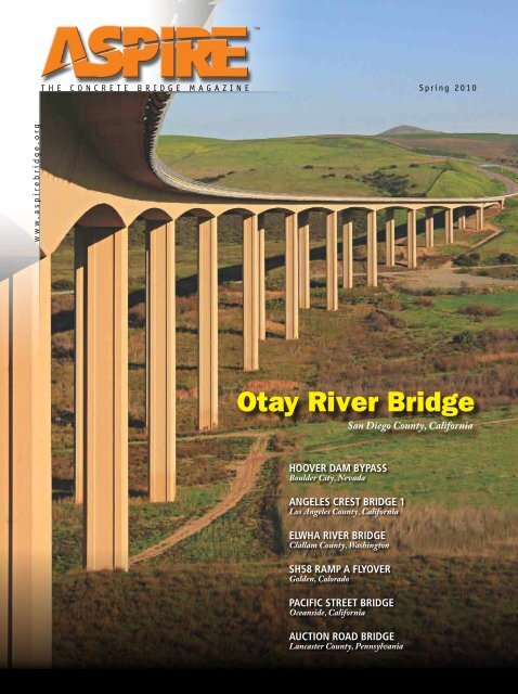
Otay River <strong>Bridge</strong><br />
San Diego County, California<br />
hoover dam bypass<br />
Boulder City, Nevada<br />
angeles crest bridge 1<br />
Los Angeles County, California<br />
elwha river bridge<br />
Clallam County, Washington<br />
SH58 Ramp a flyover<br />
Golden, Colorado<br />
pacific street bridge<br />
Oceanside, California<br />
auction road bridge<br />
Lancaster County, Pennsylvania
<strong>ASPIRE</strong>, <strong>Spring</strong> 20<strong>10</strong> | 3
Social, Economic, and Ecological Benefits<br />
of Sustainable <strong>Concrete</strong> <strong>Bridge</strong>s<br />
8<br />
Features<br />
C O N T E N T S<br />
International <strong>Bridge</strong> Technologies 8<br />
Focus on new concepts being used around the world keeps IBT<br />
growing in its <strong>10</strong>th year.<br />
Hoover Dam Bypass 16<br />
<strong>The</strong> Mike O’Callaghan–Pat Tillman Memorial <strong>Bridge</strong> at Hoover<br />
Dam set to open Fall 20<strong>10</strong>.<br />
Photo: International <strong>Bridge</strong> Technologies.<br />
12<br />
Angeles Crest <strong>Bridge</strong> 1 20<br />
Searching for a practical solution.<br />
Elwha River <strong>Bridge</strong> 24<br />
Battling the Terrain.<br />
SH58 Ramp A Flyover <strong>Bridge</strong> 28<br />
Colorado is using curved precast concrete U-girders to create<br />
cost-effective, long-span bridges where aesthetics and urban<br />
issues are key factors.<br />
Pacific Street <strong>Bridge</strong> 34<br />
Gracefully curved cast-in-place concrete bridge brings peace<br />
of mind to community.<br />
Auction Road <strong>Bridge</strong> Replacement 40<br />
Recreating an Historic Treasure.<br />
Preliminary rendering: Kiewit, HNTB, and FIGG.<br />
Rendering: Central Federal Lands Highway Division, Federal Highway Administration.<br />
16<br />
Departments<br />
Editorial 2<br />
Reader Response 4<br />
<strong>Concrete</strong> Calendar 6<br />
Perspective—Sustainable <strong>Bridge</strong>s 12<br />
Aesthetics Commentary 31, 36<br />
<strong>Concrete</strong> Connections 44<br />
FHWA—Ultra-High-Performance <strong>Concrete</strong> 46<br />
STATE—<strong>Concrete</strong> <strong>Bridge</strong>s in Oregon 48<br />
Safety and Serviceability 52<br />
COUNTY—<strong>The</strong> <strong>Bridge</strong> Replacement Program<br />
of Grant County, Washington 53<br />
AASHTO LRFD Specifications 56<br />
Photo: International <strong>Bridge</strong> Technologies.<br />
Advertisers Index<br />
<strong>Bridge</strong>scape .. . . . . . . . . . . . . . . . . . . . . . . . 27<br />
CABA . . . . . . . . . . . . . . . . . . . . . . . . . . . . . . . 3<br />
Campbell Scientific.. . . . . . . . . . . . . . . . . . 19<br />
Cortec Corporation .. . . . . . . . . . . . . . . . . . . 6<br />
DSI. . . . . . . . . . . . . . . . . . . . . . . . . . . . . . . . . 5<br />
Enerpac.. . . . . . . . . . . . . . . . . . . . . . . . . . . . 15<br />
FIGG .. . . . . . . . . . . . . . . . . Inside Front Cover<br />
Flatiron.. . . . . . . . . . . . . . . . . . . . . . . . . . . . 14<br />
Helser Industries .. . . . . . . . . . . . . . . . . . . . 45<br />
Holcim. . . . . . . . . . . . . . . . Inside Back Cover<br />
International <strong>Bridge</strong> Technologies Inc.. . . . 7<br />
Larsa.. . . . . . . . . . . . . . . . . . . . . . . . . . . . . . 55<br />
Mi-Jack Products Inc. .. . . . . . . . . . . . . . . . . 4<br />
PB.. . . . . . . . . . . . . . . . . . . . . . . . . Back Cover<br />
PCI. . . . . . . . . . . . . . . . . . . . . . . 32-33, 38, 51<br />
Poseidon Barge Corporation.. . . . . . . . . . . 37<br />
Safway .. . . . . . . . . . . . . . . . . . . . . . . . . . . . 39<br />
Shuttlelift.. . . . . . . . . . . . . . . . . . . . . . . . . . 54<br />
Splice Sleeve. . . . . . . . . . . . . . . . . . . . . . . . 27<br />
Summit Engineering .. . . . . . . . . . . . . . . . . 23<br />
T.Y. Lin International .. . . . . . . . . . . . . . . . . 43<br />
<strong>ASPIRE</strong>, <strong>Spring</strong> 20<strong>10</strong> | 1
E D I T O R I A L<br />
Photo: Ted Lacey Photography.<br />
Some of the excitement of being involved with<br />
<strong>ASPIRE</strong> magazine is receiving information<br />
about the unique and sometimes daring bridges that<br />
are being built around the country. Many of these<br />
designs would have been thought to be unbuildable a<br />
decade ago. Most of the solutions incorporate notable<br />
aesthetic provisions and long-term performance<br />
enhancements, and some are located where gaining<br />
access becomes one of the major engineering<br />
accomplishments. This issue features a mixture of<br />
such projects.<br />
As an example of the wonderful projects being<br />
presented, we asked Fred Gottemoeller to review<br />
the projects worthy of his insightful “Aesthetics<br />
Commentary.” He responded that the issue contains<br />
“an embarrassment of riches.” You can read his note<br />
in the Reader Responses on page 4.<br />
We endeavor to bring you the best and most<br />
innovative projects. We consider it our privilege to<br />
deliver the “riches” that are increasingly gracing the<br />
nation’s landscape. Further, we find it gratifying that<br />
the innovative designers, the owner agencies, and the<br />
builders eagerly share the designs and construction<br />
details that make these projects so interesting and the<br />
information so valuable.<br />
A firm that is creating such lasting designs<br />
is International <strong>Bridge</strong> Technologies (IBT) in<br />
San Diego, Calif. Just <strong>10</strong> years old, but originating<br />
from deeper roots, this group operates from six<br />
international offices and has already left its mark<br />
among noteworthy bridges. <strong>The</strong> designer FOCUS<br />
begins on page 8.<br />
<strong>The</strong> Hoover Dam Bypass, Colorado River <strong>Bridge</strong><br />
is taking shape to be one of the country’s most<br />
recognizable bridges and most amazing recent<br />
engineering accomplishments. David Goodyear of T.Y<br />
Lin International explains that, with an arch span of<br />
<strong>10</strong>60 ft, the project had many design and construction<br />
challenges to overcome. <strong>The</strong> article begins on page 16.<br />
Not far from Los Angeles, the Angeles Crest<br />
<strong>Bridge</strong> 1 was required to span a mountain wash.<br />
Precast/Prestressed<br />
<strong>Concrete</strong> Institute<br />
Silica Fume<br />
Association<br />
2 | <strong>ASPIRE</strong>, <strong>Spring</strong> 20<strong>10</strong><br />
“An Embarrassment of Riches…”<br />
John S. Dick, Executive Editor<br />
American Segmental<br />
<strong>Bridge</strong> Institute<br />
Expanded Shale Clay<br />
and Slate Institute<br />
Portland Cement<br />
Association<br />
But, to get 208-ft-long girders to the site required<br />
innovation every step of the way. Jose Higareda of the<br />
California Department of Transportation explains the<br />
development of the project beginning on page 20.<br />
<strong>The</strong> state of Oregon boasts some of the nation’s<br />
most scenic roads and bridges. Its history with<br />
concrete bridges goes back to the early part of the<br />
twentieth century. <strong>The</strong> history is chronicled starting<br />
on page 48 by Ray Bottenberg with the Oregon<br />
Department of Transportation.<br />
“If we could just curve those precast concrete<br />
girders…!” Well, the state of Colorado is doing just<br />
that. Together with innovative techniques brought to<br />
the challenge by Gregg Reese of Summit Engineering,<br />
the state is making use of curved girders to create<br />
durable, high-performing, cost-effective bridges and<br />
ramps. One of the latest, I-70 to SH58 Interchange<br />
Ramp A, is described beginning on page 28.<br />
Innovation can be found in many quarters. <strong>The</strong><br />
Federal Highway Administration’s (FHWA)’s “<strong>Bridge</strong><br />
of the Future” initiative has identified promising<br />
materials and technology. A material undergoing<br />
more development is ultra-high-performance concrete<br />
(UHPC). In the first of a two-part article, FHWA<br />
explains what UHPC is, how it may be useful in the<br />
future and where it has been used for bridges to date.<br />
See the article that starts on page 46.<br />
And there are more very interesting projects. <strong>The</strong><br />
Elwha River <strong>Bridge</strong> in Washington State (page 24), the<br />
Pacific Street <strong>Bridge</strong> in Oceanside, Calif. (page 34), and<br />
the Auction Road <strong>Bridge</strong> in Pennsylvania (page 40)<br />
round out this issue’s impressive bridges. Don’t pass<br />
up the profile of Grant County, Wash. (page 53) and its<br />
experience with concrete solutions as well.<br />
Be sure to tell us about your projects. We would love<br />
to hear about them. It’s easy to drop us a line from<br />
www.aspirebridge.org. You can help also by completing<br />
a brief survey there that will give us guidance about<br />
<strong>ASPIRE</strong>. All previous issues of <strong>ASPIRE</strong> can be viewed or<br />
downloaded from the website.<br />
Epoxy Interest Group<br />
Log on NOW at<br />
www.aspirebridge.org<br />
and take the <strong>ASPIRE</strong> Reader Survey.<br />
Executive Editor<br />
John S. Dick<br />
Managing Technical Editor<br />
Dr. Henry G. Russell<br />
Managing Editor<br />
Craig A. Shutt<br />
Editorial Administration<br />
James O. Ahtes Inc.<br />
Art Director<br />
Paul Grigonis<br />
Layout Design<br />
Tressa Park<br />
Ad Sales<br />
Jim Oestmann<br />
Phone: (847) 838-0500 • Cell: (847) 924-5497<br />
Fax: (847) 838-0555<br />
joestmann@arlpub.com<br />
Reprint Sales<br />
Paul Grigonis<br />
(312) 360-3217<br />
e-mail: pgrigonis@pci.org<br />
Publisher<br />
Precast/Prestressed <strong>Concrete</strong> Institute<br />
James G. Toscas, President<br />
Editorial Advisory Board<br />
Susan N. Lane, Portland Cement Association<br />
(PCA)<br />
John S. Dick, Precast/Prestressed <strong>Concrete</strong><br />
Institute (PCI)<br />
William R. Cox, American Segmental <strong>Bridge</strong><br />
Institute (ASBI)<br />
David McDonald, Epoxy Interest Group (EIG)<br />
Dr. Henry G. Russell, Managing Technical Editor<br />
POSTMASTER<br />
Send address changes to <strong>Aspire</strong>:<br />
200 W. Adams St., Suite 2<strong>10</strong>0<br />
Chicago, IL 60606<br />
Standard postage paid at Chicago, IL, and<br />
additional mailing offices.<br />
<strong>Aspire</strong> (Vol. 4, No. 2),<br />
ISSN 1935-2093 is published quarterly<br />
by the Precast/Prestressed <strong>Concrete</strong> Institute<br />
200 W. Adams St., Suite 2<strong>10</strong>0<br />
Chicago, IL 60606.<br />
Copyright 20<strong>10</strong>, Precast/Prestressed <strong>Concrete</strong><br />
Institute.<br />
If you have a project to be con sidered for <strong>Aspire</strong>,<br />
send information to <strong>Aspire</strong>,<br />
200 W. Adams St., Suite 2<strong>10</strong>0<br />
Chicago, IL 60606<br />
phone: (312) 786-0300<br />
www.aspirebridge.org<br />
e-mail: info@aspirebridge.org<br />
Cover<br />
Otay River <strong>Bridge</strong>, San Diego County, California<br />
Photo: Mike Palhegyi.
<strong>ASPIRE</strong>, <strong>Spring</strong> 20<strong>10</strong> | 3
R E A D E R R E S P O N S E<br />
Editor,<br />
Nice write up about Spencer Creek <strong>Bridge</strong> in<br />
<strong>ASPIRE</strong> [see <strong>ASPIRE</strong> Winter 20<strong>10</strong>, p. 16]. It<br />
turned out great and was a great job to be a<br />
part of. <strong>The</strong> article and pictures did a good job<br />
explaining the engineering and construction<br />
involved. Hope to work with both [the designer<br />
and the precaster] more in the future.<br />
Roger Silbernagel<br />
Slayden Construction Group Inc.<br />
Stayton, Ore.<br />
Editor,<br />
When you first sent me the list of projects<br />
for this issue I realized that the magazine<br />
would contain an embarrassment of riches.<br />
All of the bridges are worth comment. It’s clear<br />
that the competitions sponsored by PCA and<br />
PCI and that <strong>ASPIRE</strong> itself are encouraging<br />
better bridge design throughout the U.S. I’m<br />
honored to be a small part of it.<br />
With these riches in mind, I feel that I should<br />
say a word about why I have commented<br />
on the bridges that I did. <strong>The</strong> Hoover Dam<br />
Bypass <strong>Bridge</strong> is the obvious candidate for<br />
commentary in this issue. It is an excellent<br />
bridge and an impressive accomplishment.<br />
It will also get much attention from many<br />
directions over the next few years. <strong>The</strong><br />
more modest bridges also deserve attention,<br />
especially where they pioneer new ideas<br />
(the Ramp A Flyover) or fit perfectly into a<br />
sensitive environment (Pacific Street). So I<br />
have chosen to comment on them, with full<br />
confidence that the Hoover Dam Bypass will<br />
not be neglected.<br />
I can’t wait to see what you will be bringing<br />
to the next issue.<br />
Fred Gottemoeller<br />
<strong>Bridge</strong>scape LLC<br />
Columbia, Md.<br />
Editor,<br />
I have been following the Gratz [Route 22]<br />
<strong>Bridge</strong> [see <strong>ASPIRE</strong> Winter 20<strong>10</strong>, cover, and<br />
pp. <strong>10</strong>-11] closely as I am a bridge engineer<br />
at KTC. Great Article!!<br />
J. C. Pyles<br />
Kentucky Transportation Cabinet<br />
Frankfort, Ky.<br />
[Editor’s Reply]<br />
We expect to publish a more detailed article<br />
about this bridge in a future issue.<br />
Editor,<br />
I plan to use some articles from <strong>ASPIRE</strong><br />
<strong>Magazine</strong> as part of a bridge engineering<br />
course this spring. I was wondering if there is<br />
an easy mechanism for me to access previous<br />
issues of the magazine. <strong>The</strong> web link seems to<br />
only allow access back to <strong>Spring</strong> 2007. I am<br />
particularly interested in the AASHTO LRFD<br />
column authored by Professor Dennis Mertz.<br />
Brian D. Swartz<br />
Buchnell University<br />
Lewisburg, Pa.<br />
[Editor’s Reply]<br />
Professor…<br />
<strong>ASPIRE</strong> was launched with the Winter 2007 issue<br />
(the only one not on the web). I have attached the<br />
Dr. Mertz LRFD article from that issue.<br />
[Professor Swartz’ Response]<br />
Thanks for your quick reply. I didn’t realize<br />
<strong>ASPIRE</strong> was such a new magazine. I think<br />
<strong>ASPIRE</strong> is a great resource for the classroom. It<br />
contains a lot of reading available about new<br />
technologies and interesting aspects of bridge<br />
engineering. It is also a good source of case<br />
studies that get the students more excited—<br />
they enjoy seeing real-world applications of<br />
the textbook principles. I have particularly<br />
found Dr. Mertz’s column to cover complex<br />
concepts in straightforward language that is<br />
helpful for use in class. It’s great that it is on<br />
the web and easily accessible for the students!<br />
Editor’s Note<br />
Additional copies of <strong>ASPIRE</strong> may be purchased<br />
for a nominal price by writing to the Editor<br />
through “Contact Us” at the <strong>ASPIRE</strong> website,<br />
www.aspirebridge.org. A free subscription can be<br />
arranged there using the “Subscribe” tab.<br />
4 | <strong>ASPIRE</strong>, <strong>Spring</strong> 20<strong>10</strong>
<strong>ASPIRE</strong>, <strong>Spring</strong> 20<strong>10</strong> | 5
CONTRIBUTING AUTHORS<br />
M. Myint Lwin is director<br />
of the FHWA Office of <strong>Bridge</strong><br />
Technology in Washington, D.C.<br />
He is responsible for the National<br />
Highway <strong>Bridge</strong> Program direction,<br />
policy, and guidance, including<br />
bridge technology development,<br />
deployment and education, and the<br />
National <strong>Bridge</strong> Inventory and Inspection Standards.<br />
Dr. Benjamin A. Graybeal is a<br />
research structural engineer at the<br />
Federal Highway Administration’s<br />
Turner-Fairbank Highway<br />
Research Center in McLean,<br />
Va., where he manages the<br />
FHWA UHPC research program.<br />
Dr. Dennis R. Mertz is<br />
professor of civil engineering at the<br />
University of Delaware. Formerly<br />
with Modjeski and Masters Inc.<br />
when the LRFD Specifications<br />
were first written, he has continued<br />
to be actively involved in their<br />
development.<br />
Raymond Paul Giroux<br />
has spent 30 years with Kiewit<br />
Corporation and is district quality<br />
manager in Concord, Calif. Much<br />
of his work has been on heavy<br />
civil projects. He is a member<br />
of the American Society of Civil<br />
Engineers and the Transportation<br />
Research Board. He has also been involved with ASCE history and<br />
heritage efforts and chaired their committee celebrating the 125th<br />
anniversary of the Brooklyn <strong>Bridge</strong> in 2008<br />
April 12-13<br />
20<strong>10</strong> ASBI Grouting Certification<br />
Training<br />
J.J. Pickle Research Campus, <strong>The</strong> Commons<br />
Center, Austin, Tex.<br />
May 23-27<br />
AASHTO Subcommittee on <strong>Bridge</strong>s and<br />
Structures Annual Meeting<br />
Grand Sheraton Hotel, Sacramento, Calif.<br />
May 29 – June 2<br />
Third International fib Congress<br />
and Exhibition<br />
PCI Annual Convention<br />
PCI-FHWA National <strong>Bridge</strong> Conference<br />
Gaylord National Resort & Convention<br />
Center, National Harbor, Md.<br />
June 6-9<br />
International <strong>Bridge</strong> Conference<br />
David L. Lawrence Convention Center,<br />
Pittsburgh, Pa.<br />
June 14-19<br />
PCI Quality Control & Assurance<br />
Schools, Levels I, II & III<br />
Sheraton Music City Hotel, Nashville, Tenn.<br />
CONCRETE CALENDAR 20<strong>10</strong><br />
For links to websites, email addresses, or telephone numbers for these events, go to<br />
www.aspirebridge.org.<br />
June 22-23<br />
ASBI Construction Practices Seminar<br />
Orlando, Fla.<br />
July 11-15<br />
Fifth International Conference on<br />
<strong>Bridge</strong> Maintenance, Safety and<br />
Management<br />
International Association for <strong>Bridge</strong><br />
Maintenance and Safety (IABMAS)<br />
Loews Philadelphia Hotel, Philadelphia, Pa.<br />
September 23-26<br />
PCI Committee Days<br />
Westin Hotel, Chicago, Ill.<br />
October 11-12<br />
20<strong>10</strong> ASBI 22nd Annual Convention<br />
<strong>The</strong> Westin Bayshore, Vancouver,<br />
British Columbia, Canada<br />
October 24-28<br />
ACI Fall Convention<br />
<strong>The</strong> Westin Convention Center, Pittsburgh, Pa.<br />
December 1-3<br />
TRB-FHWA 7th International <strong>Bridge</strong><br />
Engineering Conference:<br />
Improving Reliability and Safety<br />
Grand Hyatt, San Antonio, Tex.<br />
Frederick Gottemoeller is<br />
an engineer and architect, who<br />
specializes in the aesthetic aspects<br />
of bridges and highways. He is the<br />
author of <strong>Bridge</strong>scape, a reference<br />
book on aesthetics and was deputy<br />
administrator of the Maryland State<br />
Highway Administration.<br />
MANAGING<br />
TECHNICAL EDITOR<br />
Dr. Henry G. Russell is an<br />
engineering consultant, who has<br />
been involved with the applications<br />
of concrete in bridges for over 35<br />
years and has published many<br />
papers on the applications of highperformance<br />
concrete.<br />
Photo: Ted Lacey Photography.<br />
6 | <strong>ASPIRE</strong>, <strong>Spring</strong> 20<strong>10</strong>
<strong>ASPIRE</strong>, <strong>Spring</strong> 20<strong>10</strong> | 7
F O C U S<br />
International <strong>Bridge</strong> Technologies<br />
Lives up to its Name<br />
by Craig A. Shutt<br />
<strong>The</strong> 2890-ft-long Second Vivekananda<br />
Crossing in Calcutta, India, uses the<br />
extradose concept, which features<br />
precast concrete box girders that work<br />
with low-angle stay cables. It provides<br />
a new and developing concept for<br />
medium-span bridges with clearance<br />
issues.<br />
Photos and renderings:<br />
International <strong>Bridge</strong> Technologies.<br />
Focus on new<br />
concepts being used<br />
around the world<br />
keeps IBT growing<br />
in its <strong>10</strong>th year<br />
International <strong>Bridge</strong> Technologies (IBT),<br />
celebrating its <strong>10</strong>th anniversary of<br />
operation this year, embodies its name<br />
in virtually every project it undertakes.<br />
Its record of accomplishments around<br />
the globe already has been notable, and<br />
it expects its approach to innovation and<br />
international work will continue. Some<br />
of that work will come via advancements<br />
in concrete material and construction<br />
techniques, which IBT uses in a high<br />
percentage of its projects.<br />
“We’ve found there’s a lot of value<br />
in trying to be ahead of the curve<br />
of creating new ideas for bridge<br />
construction,” says Chris Hall, one<br />
of IBT’s three founders. “We’ve had<br />
considerable success in our <strong>10</strong> years and<br />
have seen a lot of growth. We believe<br />
it derives from our willingness to be<br />
open to new solutions. Everyone wants<br />
to be innovative, of course, but we’ve<br />
had many opportunities, especially<br />
through the design-build process, to<br />
work outside the box with contractors<br />
and not be told ‘no.’ ”<br />
<strong>The</strong> company’s expertise with concrete<br />
construction techniques has a strong<br />
foundation. IBT was founded in San<br />
Diego by Daniel Tassin, Michael Smart,<br />
and Hall. <strong>The</strong> three gained experience<br />
at Jean Muller International Inc. (JMI),<br />
whose founder developed the technique<br />
of precast concrete segmental bridge<br />
construction. “His focus was always on<br />
marrying new construction techniques<br />
to efficient designs,” Hall says. Muller, in<br />
turn, studied under Eugene Freyssinet,<br />
the inventor of modern prestressing<br />
techniques.<br />
“Our historical relationship with designbuild<br />
contractors has really created the<br />
framework for practical innovation.”<br />
says Hall. “Being close to construction<br />
lets us understand the issues that<br />
need to be addressed in our designs.<br />
More important are the relationships<br />
built over time. Through successful<br />
collaborations, we have established<br />
the trust that allows our concepts to<br />
advance into practice.”<br />
Five International Offices<br />
In just one decade, the company<br />
has grown to encompass employees<br />
working from five offices around the<br />
world: San Diego, USA; Bangkok,<br />
Thailand; Mexico City, Mexico;<br />
Vancouver, Canada; and Abu Dhabi,<br />
United Arab Emirates. From those<br />
locations, the company has designed<br />
projects in Canada, Puerto Rico, India,<br />
Abu Dhabi, Mexico, Australia, Jamaica,<br />
and the United States.<br />
8 | <strong>ASPIRE</strong>, <strong>Spring</strong> 20<strong>10</strong>
“Our name was an intentional decision<br />
on our part to ensure we focused on<br />
technological aspects of construction,”<br />
Hall explains. “At JMI, our emphasis was<br />
specialty projects, and that has carried<br />
over.” <strong>The</strong> company’s first project, in<br />
Taiwan, was in partnership with JMI.<br />
<strong>The</strong> project consisted of a 120-mile-long<br />
elevated high-speed rail line, which was<br />
constructed with cast-in-place concrete.<br />
<strong>The</strong> project exemplifies the way IBT<br />
approaches its projects, says Hall. “<strong>The</strong><br />
owners had a prescribed solution using<br />
full-span precast concrete box girders,”<br />
he explains. “We studied the goals<br />
and the materials, and we found what<br />
we considered a more constructable<br />
alternative.” <strong>The</strong>y developed a Movable<br />
Scaffolding System (MSS) to cast the<br />
concrete superstructure. “It made<br />
construction of the spans more efficient<br />
and eliminated transportation issues of<br />
hauling large box girders to the site.”<br />
Another notable international project<br />
is the Second Vivekananda Crossing in<br />
Calcutta, India. A 2890-ft-long precast<br />
concrete segmental bridge with typical<br />
spans of 361 ft, it represents a relatively<br />
new concept: an extradosed bridge,<br />
which is described as a combination<br />
between a girder and a cable-stayed<br />
bridge, using a stiff box-girder that<br />
works with low-angle stay cables. “We<br />
were one of the first North American<br />
firms to have designed this bridge type,<br />
and maybe the first to have one open<br />
to traffic,” Hall says. “Although its<br />
application is fairly narrow, it represents<br />
a good concept for medium-span<br />
bridges that have clearance issues.”<br />
North American Projects<br />
One of the most honored of its<br />
American projects is the Otay River<br />
<strong>Bridge</strong> in IBT’s hometown of San<br />
Diego. <strong>The</strong> 3325-ft-long bridge was<br />
constructed 150 ft above grade over<br />
an environmentally sensitive river valley.<br />
<strong>The</strong> twin 12-span structures feature<br />
precast concrete variable-depth box<br />
girders constructed using the balancedcantilever<br />
method, the first such bridge<br />
to open to traffic in the state. More<br />
details of this project are provided in the<br />
<strong>Spring</strong> 2007 issue of <strong>ASPIRE</strong>.<br />
“Caltrans was concerned about the<br />
performance capabilities of this type of<br />
bridge in a high-seismic zone, as there<br />
wasn’t much history,” Hall explains.<br />
But tests conducted at the University of<br />
California–San Diego showed “precast<br />
concrete segmental designs are very<br />
desirable for these applications, with<br />
very good behavioral characteristics in<br />
high-seismic zones.” <strong>The</strong> state now is<br />
considering more projects built in this<br />
manner.<br />
Another project featuring precast<br />
concrete segmental box girders was<br />
completed at nearly the same time. <strong>The</strong><br />
Sound Transit Central Link Light Rail<br />
System in Seattle, Wash., featured in<br />
the Fall 2007 issue of <strong>ASPIRE</strong>, contains<br />
4.2 miles of elevated guideway<br />
carrying twin tracks with continuously<br />
welded rails fastened to the top of the<br />
structure. Two stations are located along<br />
the alignment, which passes through<br />
environmentally sensitive areas.<br />
<strong>The</strong> precast concrete girders feature<br />
a unique V-shaped triangular cross<br />
section developed specifically for this<br />
project, Hall notes. <strong>The</strong> design optimized<br />
superstructure quantities and reduced<br />
the visual impact when observed from<br />
ground level.<br />
“Precast concrete segmental construction<br />
is commonly used for elevated transit,<br />
especially overseas, because these<br />
projects often are constructed in<br />
congested corridors, where delivering<br />
precast components alleviates site<br />
disruption,” he explains. “But we realized<br />
that these designs use box sections that<br />
waste a lot of material in the bottom<br />
‘We’ve found<br />
there’s a lot of value in<br />
trying to be ahead of<br />
the curve.’<br />
half of the section. <strong>The</strong> V-shape design<br />
thinned down the concrete quantities<br />
significantly and improved the visual<br />
appearance. It was a good solution, both<br />
technically and aesthetically.”<br />
Several Vancouver Projects<br />
<strong>The</strong> firm also has done considerable<br />
international work in Vancouver, Canada,<br />
where it opened its newest office. <strong>The</strong><br />
city, which hosted the 20<strong>10</strong> Winter<br />
Olympics, committed to a number of<br />
large bridge and infrastructure projects<br />
as part of British Columbia’s Gateway<br />
Program. Begun in 2003, its aim is to<br />
facilitate movement of people, goods,<br />
and transit through the city. “Vancouver<br />
wants to become a key international port<br />
city, and they used the Olympics as a<br />
catalyst,” Hall says.<br />
Tassin and other IBT engineers, while at<br />
JMI, worked with Canadian officials on<br />
projects such as the Confederation <strong>Bridge</strong><br />
to Prince Edward Island, a landmark<br />
precast concrete segmental bridge<br />
and the Millennium Line extension to<br />
Vancouver’s light rail system. “We had<br />
a good presence in Canada, and a lot<br />
of good engineering work comes out of<br />
good relationships.”<br />
A project currently underway is the<br />
6801-ft-long Port Mann <strong>Bridge</strong> carrying<br />
the <strong>10</strong>-lane Trans Canada Highway<br />
across the Fraser River, which IBT is<br />
designing in collaboration with T.Y. Lin<br />
International. <strong>The</strong> crossing includes a<br />
2789-ft-long, cable-stayed bridge with a<br />
main span of 1542 ft and 4012-ft-long<br />
Precast concrete<br />
segmental designs<br />
offer good behavioral<br />
characteristics in highseismic<br />
zones.<br />
<strong>The</strong> 3325-ft-long Otay River <strong>Bridge</strong> in San Diego, Calif., features twin variable-depth box<br />
girders connected by a transverse diaphragm at the piers and cast-in-place slab along the<br />
bridge’s centerline. <strong>The</strong> 640 trapezoidal box girder segments, erected via the balancedcantilever<br />
method, used a self-launching overhead gantry to minimize site disruptions.<br />
<strong>ASPIRE</strong>, <strong>Spring</strong> 20<strong>10</strong> | 9
<strong>The</strong> Sound Transit Central Link Light Rail<br />
System in Seattle, Wash., uses precast<br />
concrete girders with a unique V-shaped<br />
triangular cross section developed<br />
specifically for this project. <strong>The</strong> design<br />
optimized superstructure quantities and<br />
reduced the visual impact when observed<br />
from ground level.<br />
‘A lot of good engineering work comes out of<br />
good relationships.’<br />
land supported on falsework, and a<br />
traveler used over the water. <strong>The</strong> floor<br />
beams are cast-in-place over the water<br />
whereas precast beams are used over<br />
land.<br />
precast concrete segmental box girder<br />
approaches built using balanced<br />
cantilever construction above the water<br />
and span-by-span construction over land.<br />
Cable-Stayed <strong>Bridge</strong>s Grow<br />
IBT has completed two other cable-stayed<br />
projects using this same combination of<br />
materials in the city, the Coast Meridian<br />
Overpass and the Pitt River <strong>Bridge</strong>.<br />
“<strong>The</strong>se are often called ‘steel’ cablestayed<br />
bridges because the main bridge<br />
structure has steel girders, but there’s<br />
a large amount of concrete included in<br />
them, with precast concrete deck panels<br />
and cast-in-place concrete pylons and<br />
foundations,” Hall notes. “It’s a bit of<br />
a misnomer to call them ‘steel’ when<br />
concrete plays such a critical role. You<br />
really can’t beat concrete, particularly for<br />
compression elements.”<br />
Together with AECOM, the company<br />
recently completed the design of an<br />
all-concrete cable-stayed structure<br />
for the 2600-ft-long Indian River Inlet<br />
replacement bridge near Delaware<br />
Seashore State Park. <strong>The</strong> design features<br />
two 240-ft-tall concrete pylons on<br />
either side of the deck, each supporting<br />
a single plane of stays. It will provide a<br />
950-ft-long main span over the inlet with<br />
1650 ft of bridge deck over the land. All<br />
supports will be placed out of the water,<br />
due to the extreme scour experienced<br />
by the existing bridge. <strong>The</strong> bridge will<br />
be supported by 36-in.-square precast<br />
concrete piles.<br />
<strong>The</strong> design provides a minimum <strong>10</strong>0-<br />
year service life, a critical component<br />
for officials and the key reason for<br />
the all-concrete design. Achieving<br />
this goal required adding several<br />
features, including epoxy-coated<br />
steel reinforcement, stainless-steel<br />
embedments, low-permeability concrete,<br />
and a latex-modified overlay. In addition,<br />
the superstructure was designed for zero<br />
tensile stress under service loads.<br />
“Long-term maintenance costs were a<br />
major concern, and the owner decided<br />
upfront that maintaining a steel structure<br />
would be too costly.” <strong>The</strong> design<br />
incorporates innovative construction<br />
methods, with the deck sections above<br />
“Using concrete for all of the<br />
components produces a slight premium<br />
on initial costs,” Hall says. “But when<br />
owners are looking at the total lifecycle<br />
costs, then concrete cable-stayed<br />
designs are very competitive.” Owners,<br />
unfortunately, are forced to put a<br />
premium on initial costs instead of being<br />
able to factor costs over a longer horizon.<br />
“It’s hard to get past the initial cost,” he<br />
says. “But there’s an evolution occurring,<br />
and owners are becoming more aware<br />
of the positive impact that cable-stayed<br />
designs can have.” <strong>The</strong>y’re still gaining a<br />
foothold in the United States though, so<br />
‘Owners are<br />
becoming more aware<br />
of the positive impact<br />
that cable-stayed<br />
designs can have.’<br />
<strong>The</strong> 2600-ft-long Indian River Inlet<br />
replacement bridge features an<br />
all-precast concrete cable-stayed<br />
superstructure with a projected <strong>10</strong>0-<br />
year minimum service life. Owners<br />
required concrete to ensure low longterm<br />
maintenance costs throughout the<br />
structure’s life.<br />
<strong>10</strong> | <strong>ASPIRE</strong>, <strong>Spring</strong> 20<strong>10</strong>
states are still hesitant to consider them.<br />
Cable-stayed designs also must fight their<br />
reputation. “<strong>The</strong>y’re often considered<br />
‘landmark’ designs, which equates to<br />
being fancy—which means expensive.”<br />
In fact, the concept was developed in<br />
post-war Germany to exploit material<br />
efficiencies. “<strong>The</strong> market for stays and<br />
stay hardware is robust, and increasingly<br />
competitive, which can create a very costeffective<br />
and efficient design, especially<br />
for spans longer than 500 ft. This has<br />
added advantages where slightly longer<br />
spans can help mitigate impacts to a<br />
sensitive environment.”<br />
Owners Demand Speed<br />
Owners are studying options more<br />
closely as designs are proven in the<br />
field and costs are reconsidered. <strong>The</strong>y<br />
also are demanding one other element:<br />
faster construction. “Speed has taken a<br />
huge leap forward,” Hall says. In part,<br />
the design-build delivery approach has<br />
been a factor. “Design-build teams have<br />
proven the process can be sped up and<br />
demonstrates that schedules can be<br />
compressed,” he explains. “Now, owners<br />
are seeing that high-quality bridges<br />
can be safely constructed a lot quicker<br />
than they realized—and they want that<br />
compressed time.”<br />
That expectation leaves little room for<br />
maneuvering. “It’s reaching a point of<br />
equilibrium, where the push for speed<br />
has begun to obscure potential cost<br />
efficiencies,” he notes. “<strong>The</strong>re is a sweet<br />
spot between cost and speed that has<br />
to be acknowledged, and squeezing<br />
too tightly can have an impact on cost<br />
that isn’t worth the time gained. It’s a<br />
judgment call on each project.”<br />
‘<strong>The</strong>re is a sweet spot between cost and speed<br />
that has to be acknowledged.’<br />
channel bridge is being designed with<br />
precast concrete components to replace<br />
a four-span steel girder structure. <strong>The</strong><br />
short-span bridge features two large<br />
edge girders that will serve as the<br />
roadway barriers, reducing material and<br />
increasing vertical clearance. <strong>The</strong> bridge’s<br />
total depth will be 5 ft 4 in., including<br />
barriers. “It offers an opportunity for<br />
a quick replacement on a small span<br />
by bringing in a few precast concrete<br />
components and assembling them<br />
quickly on site,” he explains.<br />
New concrete technologies are aiding<br />
new designs. “<strong>Concrete</strong> is both science<br />
and art,” Hall says. “More and more is<br />
being done to improve its capabilities.”<br />
For instance, significant efforts are<br />
underway to enhance performance of<br />
concrete decks by expanding and refining<br />
concrete properties to create more<br />
durable structures with lower concrete<br />
permeability.<br />
“<strong>The</strong> condition of decks is the most<br />
visible aspect of the bridge’s condition to<br />
users, and it’s the first part to go because<br />
of the wear and exposure,” he says.<br />
“Modifications to the mix designs can<br />
really aid that aspect and provide better<br />
concrete products.” Self-consolidating<br />
concrete also is producing new solutions<br />
and its use will continue to grow, he<br />
adds.<br />
Hall expects more concrete technologies<br />
to arrive in the future. “<strong>Concrete</strong><br />
segmental bridge projects have seen a<br />
lot of success,” he notes. “<strong>The</strong> DOTs<br />
and bridge owners are still building their<br />
level of comfort with the capabilities of<br />
segmental construction as more are built<br />
and a record of their service life grows.<br />
We believe precast segmental designs still<br />
have a lot of potential for expanding even<br />
further.”<br />
“<strong>The</strong>re is still a lot of opportunity to<br />
innovate and explore new design and<br />
construction options,” Hall says. “We<br />
honestly didn’t know for certain how<br />
true that would be when we started out<br />
<strong>10</strong> years ago. But we found there are<br />
definitely ways to take bridge concepts<br />
to the next generation so that owners<br />
benefit, time is saved, and projects are<br />
delivered at a lower cost.”<br />
‘<strong>The</strong>re is still a<br />
lot of opportunity to<br />
innovate and explore<br />
new design and<br />
construction options.’<br />
<strong>The</strong> motivation to finish bridges quickly<br />
is easy to understand, he adds. Much<br />
of America’s aging infrastructure—<br />
built in the 1950s with a 50-year life<br />
span—is reaching the end of its service<br />
life. But swapping old for new can be<br />
difficult with communities built around<br />
these access points. “<strong>Bridge</strong>s, especially<br />
concrete ones, have shown a lot of<br />
resilience to date, but you can squeeze<br />
out extra service life for only so long.”<br />
New Designs Tested<br />
IBT is currently testing a technology in<br />
Massachusetts, where the 248-ft-long<br />
Randolph Department of Conservation<br />
and Recreation (DCR) Access Road<br />
<strong>The</strong> DCR Access Road over Route 24 <strong>Bridge</strong> in Randolph, Mass., now underway, uses<br />
two large edge girders as roadway barriers, reducing materials and increasing vertical<br />
clearance. <strong>The</strong> low profile adds 2.5 ft to the vertical clearance without altering the<br />
approach grade.<br />
<strong>ASPIRE</strong>, <strong>Spring</strong> 20<strong>10</strong> | 11
P E R S P E C T I V E<br />
Denver’s T-Rex Project resulted from the Colorado<br />
Department of Transportation and the Regional<br />
Transportation District teaming to deliver the nation’s<br />
first multimodal project to use the design-build delivery<br />
method. Seventy-five bridges and tunnels were built<br />
as part of the project, which has enhanced national,<br />
regional, and local mobility along the I-25 and I-225<br />
corridors. Photo: Kiewit Corporation.<br />
sustainable bridges<br />
A Contractor’s<br />
Perspective<br />
<strong>The</strong> entire<br />
construction team<br />
must do its part to<br />
ensure sustainable<br />
design is effective<br />
by Raymond Paul Giroux,<br />
Kiewit Pacific Co.<br />
For generations, building good bridges<br />
has proved to be a moving target, as<br />
design criteria and standards evolve to<br />
meet society’s changing needs. Recently,<br />
designs have been further complicated<br />
by society’s increasing demands on<br />
bridge infrastructure in the face of<br />
dwindling resources. As a result, we<br />
hear more and more about the need<br />
for “sustainable solutions” in the bridge<br />
market. To achieve this goal, all on the<br />
construction team must do their part.<br />
Those efforts are complicated by the<br />
lack of a generally accepted definition<br />
of a “sustainable bridge” or a simple<br />
litmus test to determine if a bridge<br />
design is sustainable. Criteria for<br />
sustainable bridges have proven to be<br />
somewhat complicated, vague, and<br />
at times controversial. Yet sustainable<br />
bridge development is essentially about<br />
stewardship of our resources and<br />
making smart bridge decisions that not<br />
only meet society’s current needs but<br />
also their needs in the future.<br />
We face the challenge of maximizing<br />
transportation funding in difficult<br />
economic times, with an ever-aging<br />
bridge inventory and a growing demand<br />
for infrastructure. While bridges are<br />
built locally, each plays a role in the<br />
bigger picture of strategic regional<br />
and national infrastructure planning.<br />
Accordingly, proper management of<br />
our bridges is essential to achieving<br />
sustainable bridge solutions on a<br />
national, regional, and local level.<br />
We all need to be aware of the big<br />
picture, but we each can do more<br />
to achieve the final goal. First and<br />
foremost, everyone involved must stress<br />
“life-cycle” costs and economy as the<br />
primary goal in bridge design.<br />
Sustainable Examples<br />
Abound<br />
We are beginning to see this “bigpicture<br />
strategic” thinking around the<br />
country. Denver’s I-25 Transportation<br />
Expansion provides an excellent<br />
example of sustainable infrastructure<br />
development. Known as the “T-Rex”<br />
project, it used a unique collaboration<br />
between the Colorado Department<br />
of Transportation and the Regional<br />
Transportation District to become the<br />
nation’s first multimodal project to use<br />
the design-build delivery method.<br />
Completed in 2006, the $1.28-billion<br />
Kiewit Corporation-led joint venture<br />
reconstructed 17 miles of I-25 and I-225<br />
and constructed 19 miles of doubletrack,<br />
light-rail transit lines, 13 lightrail<br />
stations, three parking structures,<br />
eight interchanges, and more than 75<br />
bridges and tunnels. All construction<br />
was performed to minimize disruption<br />
to the public and the environment.<br />
12 | <strong>ASPIRE</strong>, <strong>Spring</strong> 20<strong>10</strong>
Missouri’s “Safe and Sound” initiative,<br />
an ambitious upgrade to the state’s<br />
<strong>10</strong>,000-plus bridges, focuses on<br />
approximately 1<strong>10</strong>0 structures in<br />
poor to serious condition. With an<br />
emphasis on safety, mobility, efficiency,<br />
and value, Missouri Department of<br />
Transportation officials packaged 554<br />
bridge replacements into a single<br />
design-build contract. <strong>The</strong> $487-million<br />
contract was awarded in May 2009 to<br />
KTU Constructors, comprising Kiewit<br />
Corporation, Traylor Bros. Inc., United<br />
Contractors Inc., HNTB Corp., and <strong>The</strong><br />
LPA Group Inc.<br />
More and more we see owners placing<br />
emphasis on sustainable solutions as<br />
part of a well planned infrastructure<br />
program. In planning Honolulu’s new<br />
20-mile-long elevated rail line that will<br />
connect West Oahu with downtown<br />
Honolulu, the City and County of<br />
Honolulu placed an emphasis on<br />
sustainable solutions. In Kiewit Pacific’s<br />
2009 winning design/build proposal,<br />
concrete piers and precast concrete<br />
guideways provided many sustainable<br />
elements and opportunities for aesthetic<br />
treatments.<br />
<strong>Concrete</strong>: A Green Solution<br />
Materials used in bridges need to be<br />
continually evaluated and researched<br />
to create improvements. In this regard,<br />
concrete proves to be a “green” bridge<br />
material by almost any measure:<br />
• T h e u s e o f s u p p l e m e n t a r y<br />
cementitious materials such as fly ash,<br />
slag, and silica fume<br />
• Carbon dioxide (CO 2<br />
) sequestration<br />
capability (ability to absorb CO 2<br />
)<br />
• <strong>The</strong> energy cost of production<br />
(reinforced concrete is 2.5 Gigajoules/<br />
metric ton (GJ/t); steel: 30 GJ/t)<br />
• Low solar reflectance compared to<br />
asphalt, creating reduced heat-island<br />
effect in urban areas<br />
• <strong>The</strong> recyclability of concrete and<br />
reinforcing steel<br />
Other advanced bridge materials may also<br />
improve the sustainability of our bridges:<br />
• Ultra-high-performance concrete (UHPC),<br />
offering 25,000 to 30,000 psi with<br />
correspondingly high tensile strength<br />
• Self-consolidating concrete and<br />
lightweight concrete<br />
• Improved reinforcing steels (high strength<br />
and corrosion resistant)<br />
• Carbon dioxide-absorbing materials<br />
• Recycled materials and recyclability of<br />
materials<br />
Improvements in sustainability will<br />
also come from improving means and<br />
methods to build our bridges, which<br />
will reduce environmental impacts<br />
and road-user impacts. Some of these<br />
methods will include the use of erection<br />
trusses, balanced-cantilever methods,<br />
prefabricated assemblies, and selfpropelled<br />
modular transporters (SPMTs).<br />
Focus on Life Span<br />
<strong>Bridge</strong>s currently provide an average<br />
life span of 40 to 45 years, with decks<br />
replaced every 20 years. Doubling this<br />
life span would dramatically improve the<br />
overall sustainability of bridges. Extending<br />
service life will start with adoption of<br />
various options for improved design details:<br />
• Simplification of details<br />
• Adaptable substructure designs<br />
• Consideration for bridge inspection,<br />
monitoring, and maintenance<br />
• Allowance for future modifications<br />
and retrofitting mass transit<br />
• Consideration of utility corridors<br />
along bridge alignments<br />
• Focus on context-sensitive solutions<br />
Extending service<br />
life will start with<br />
adoption of improved<br />
design details.<br />
Key Questions to Answer<br />
<strong>The</strong> February 2009 issue of Civil<br />
Engineering featured a special section<br />
suggesting “Guiding Principles<br />
for Critical Infrastructure.” <strong>The</strong><br />
authors noted, “We tend to take<br />
our infrastructure for granted until<br />
something goes wrong—often terribly<br />
wrong.” To that end, it suggested some<br />
hard questions for all of us to consider:<br />
• Have we ignored the need to<br />
manage and communicate risks?<br />
• Have we failed to consider critical<br />
infrastructure as part of a complex<br />
system?<br />
• Have we neglected to call for<br />
upgrades as conditions have<br />
changed?<br />
• Have we allowed the intertwined<br />
pressures of cutting time from<br />
schedules and reducing costs to<br />
prevail over the principle purpose of<br />
our built infrastructure—to protect<br />
the safety, health, and welfare of the<br />
public?<br />
Improving the sustainability of our<br />
bridges will not come from one change<br />
in federal regulations, nor from one<br />
new structural analysis, one new super<br />
bridge material, one new design detail,<br />
one new construction method, nor one<br />
new maintenance procedure. Clear<br />
vision and improved sustainability for<br />
bridge projects will come from all of us<br />
in the bridge industry working toward a<br />
common goal.<br />
___________<br />
This article was taken from a more<br />
detailed paper presented by the<br />
author at the Construction Research<br />
Congress, “Building a Sustainable<br />
Future,” held in Seattle, Wash.,<br />
April 5-7, 2009. <strong>The</strong> full paper can<br />
be downloaded from the <strong>ASPIRE</strong><br />
website: www.aspirebridge.org,<br />
click on “Resources” and select<br />
“Referenced Papers.”<br />
<strong>The</strong> City and County of Honolulu placed an emphasis on sustainable solutions for<br />
Honolulu’s new 20-mile elevated rail line. <strong>Concrete</strong> offered many advantages to meet<br />
the needs of the project. Preliminary rendering: Kiewit, HNTB, and FIGG.<br />
Paul Giroux can be reached at<br />
paul.giroux@kiewit.com.<br />
<strong>ASPIRE</strong>, <strong>Spring</strong> 20<strong>10</strong> | 13
14 | <strong>ASPIRE</strong>, <strong>Spring</strong> 20<strong>10</strong>
<strong>ASPIRE</strong>, <strong>Spring</strong> 20<strong>10</strong> | 15
P R O J E C T<br />
hoover dam bypass<br />
by David Goodyear, T.Y. Lin International<br />
<strong>The</strong> Mike<br />
O’Callaghan–Pat<br />
Tillman Memorial<br />
<strong>Bridge</strong> at Hoover<br />
Dam set to open Fall<br />
20<strong>10</strong><br />
A project team of five U.S. government<br />
agencies, lead by the Central Federal<br />
Lands Highway Division of the Federal<br />
Highway Administration (CFLHD)<br />
collaborated to develop a highway bypass<br />
to the existing U.S. Highway 93 over the<br />
Hoover Dam. <strong>The</strong> existing highway route<br />
over the dam mixed the throng of tourists<br />
for whom the dam is a destination with<br />
heavy highway traffic and commercial<br />
trucking. <strong>The</strong> blend of these two created<br />
hazards and hardships for both, and<br />
served as a bottleneck for commerce<br />
along this major north-south route.<br />
Project Development<br />
A consortium of firms working under the<br />
moniker of HST (HDR, Sverdrup, and T.Y.<br />
Lin International) teamed with specialty<br />
sub-consultants and CFLHD to deliver<br />
<strong>The</strong> <strong>10</strong>60-ft-span twin rib arch of the Mike O’Callaghan–Pat Tillman Memorial <strong>Bridge</strong><br />
spanning the Colorado River near the Hoover Dam.<br />
Photos: Central Federal Lands Highway Division, Federal Highway Administration.<br />
the final design for 1.6 km (1 mile)* of<br />
approach roadway in Arizona, 3.5 km<br />
(2.2 miles) of roadway in Nevada, and a<br />
major 6<strong>10</strong>-m (2000-ft) -long Colorado<br />
River crossing about 450 m (1475 ft)<br />
downstream of the historic Hoover Dam.<br />
<strong>Bridge</strong> Type Screening<br />
Process<br />
With the selection of an alignment so<br />
close to Hoover Dam, the new bridge<br />
will be a prominent feature within the<br />
Hoover Dam Historic District, sharing the<br />
view-shed with one of the most famous<br />
engineering landmarks in the United<br />
States. <strong>The</strong> environmental document set<br />
a design goal to minimize the height of<br />
the new bridge crossing on the horizon<br />
when viewed from both the dam and<br />
Lake Mead. <strong>The</strong> State Historic Preservation<br />
Officers for both Nevada and Arizona—<br />
both members of the Design Advisory<br />
Panel—emphasized the need to<br />
complement and not compete with the<br />
architecture of the dam.<br />
____________<br />
* <strong>The</strong> Mike O’Callaghan–Pat Tillman Memorial<br />
<strong>Bridge</strong> at Hoover Dam was designed using SI<br />
units. Conversions are included for the benefit<br />
of the reader.<br />
CFLHD took full advantage of prior<br />
studies and public processes to focus on<br />
the alternatives that met all the design<br />
objectives. As a result of this screening<br />
process, the type study proceeded with<br />
only deck arch options.<br />
Major Design Features<br />
<strong>The</strong> final design went through an evolution<br />
of form dictated by the engineering<br />
demands on the structure to arrive at the<br />
twin rib-framed structure. At the outset<br />
of design it was assumed that earthquake<br />
loading would control the lateral design of<br />
the bridge. A project specific probabilistic<br />
seismic hazards analysis was conducted<br />
in order to assess the range of ground<br />
motion associated with return periods<br />
appropriate for design. A <strong>10</strong>00-year return<br />
period was selected resulting in a design<br />
basis peak ground acceleration of 0.2g.<br />
Wind was also a major environmental<br />
loading condition from the outset of<br />
design. During the preliminary design<br />
phase, a site wind study was conducted<br />
to correlate the wind speeds at the bridge<br />
site with those at the Las Vegas Airport in<br />
the valley. With this correlation, the longterm<br />
statistics from the airport were used<br />
to develop site wind speeds for design. As<br />
profile<br />
mike o'callaghan–pat tillman memorial bridge<br />
(hoover dam bypass, colorado river bridge) / boulder city, NEVADA<br />
bridge design ENGINEER: T.Y. Lin International, Olympia, Wash., in collaboration with HDR Engineering, Omaha, Neb.<br />
construction ENGINEERs: OPAC, San Francisco, Calif., and McNary Bergeron, Denver, Colo.<br />
project delivery: Central Federal Lands Highway Division, Federal Highway Administration, Denver, Colo.<br />
PRIME CONTRACTOR: Obayashi PSM, JV; San Francisco, Calif.<br />
concrete supplier: Casino Redi-Mix, Las Vegas, Nev.<br />
POST-TENSIONING CONTRACTOR: Schwager-Davis, San Jose, Calif.<br />
bridge bearings: R.J. Watson, Buffalo, N.Y.<br />
16 | <strong>ASPIRE</strong>, <strong>Spring</strong> 20<strong>10</strong>
A consortium of<br />
firms teamed with<br />
specialty subconsultants<br />
and Central<br />
Federal Lands Highway<br />
Division to deliver the<br />
final design.<br />
a result, the 3-second wind speed of 56 m/<br />
sec (125 mph) was used. Dynamic studies<br />
resulted in a gust loading factor of 2.4,<br />
which collectively resulted in wind controlling<br />
the design for lateral forces. <strong>The</strong>refore, the<br />
ensuing design for seismic resistance was<br />
based on essentially elastic criteria.<br />
Arch Framing<br />
<strong>The</strong> <strong>10</strong>60-ft-span, 70 MPa (<strong>10</strong>,<strong>10</strong>0 psi)<br />
concrete arch is an efficient element for<br />
gravity loads in its final form. <strong>The</strong>re were<br />
two aspects of design that resulted in<br />
twin ribs instead of a typical single box<br />
section for this arch. <strong>The</strong> first is one of<br />
practical construction. A single box would<br />
be almost 20 m (66 ft) wide, and weigh<br />
approximately 30 metric tons/m (20 kip/ft).<br />
This section size would rule out a precast<br />
segmental option.<br />
<strong>The</strong> second aspect is the matter of<br />
performance under extreme lateral forces.<br />
At the time the framing plan was devised,<br />
the level of seismic ground motion had not<br />
been determined. A single arch rib would<br />
leave no opportunity for tuning stiffness or<br />
for providing for frame ductility, whereas<br />
twin ribs could provide an excellent means<br />
of creating ductile Vierendeel links that<br />
could otherwise fully protect the gravity<br />
system of the arch.<br />
Spandrel Framing<br />
T h e c o m p o s i t e s t e e l - c o n c r e t e<br />
superstructure was selected for speed<br />
Following closure of the arch, the spandrel columns were set using the high-line crane.<br />
Superstructure girders are shown being erected.<br />
of erection and to reduce the weight on<br />
the arch. <strong>The</strong> spacing of spandrels was<br />
an extension of the concept to erect the<br />
bridge using a highline (tramway) crane<br />
system. Above <strong>10</strong>0 kips, there is a jump<br />
in highline cost, so the decision was made<br />
to target a <strong>10</strong>0 kip maximum weight for<br />
major superstructure elements. <strong>The</strong> span<br />
was set in the range that a high-line crane<br />
could deliver the steel box sections, which<br />
resulted in a nominal 37-m (121-ft) span.<br />
This span also allows steel girders to be<br />
set within the range of most conventional<br />
cranes, if an alternative erection system<br />
had been selected. <strong>The</strong> statical system<br />
includes sliding bearings for the short, stiff<br />
piers over the arch crown, and similar piers<br />
near the abutments. This was necessary<br />
due to the large secondary moments<br />
developed in these piers from creep<br />
deflections of the arch, and also produced<br />
a more even distribution of longitudinal<br />
seismic forces among the piers.<br />
Pier Cap Framing<br />
Integral concrete pier caps were selected<br />
over steel box cap sections. <strong>The</strong>se<br />
provided lateral bracing of the spandrel<br />
columns and ultimate stability to the<br />
flexible columns in the longitudinal<br />
direction. <strong>Concrete</strong> was selected over<br />
steel due to the higher maintenance and<br />
inspection costs associated with fracture<br />
critical steel diaphragms, even though<br />
steel caps might have a lower first cost.<br />
Open Spandrel Crown<br />
An open spandrel crown was selected<br />
over the option of an integral crown.<br />
A special consideration was that the<br />
CAST-IN-PLACE CONCRETE SEGMENTAL ARCH WITH PRECAST CONCRETE SEGMENTAL COLUMNS / NEVADA AND<br />
ARIZONA DEPARTMENTS OF TRANSPORTATION, OWNERS<br />
REINFORCement SUPPLIER: Harris Rebar, Phoenix, Ariz.<br />
form traveler: NRS, Bangkok, Thailand<br />
BRIDGE DESCRIPTION: A 1900-ft-long bridge over the Colorado River at Hoover Dam, with a <strong>10</strong>60-ft-long concrete arch main span, up to 302-ft-tall<br />
precast concrete segmental columns, and cast-in-place concrete deck.<br />
structural components: <strong>The</strong> arch is a twin rib hollow box section with Vierendeel struts connecting the twin ribs. Columns are twin precast<br />
concrete segmental box structures. <strong>The</strong> roadway deck is a steel-concrete composite box girder frame with integral post-tensioned, cast-in-place concrete<br />
pier caps.<br />
BRIDGE CONSTRUCTION COST: $114 million<br />
<strong>ASPIRE</strong>, <strong>Spring</strong> 20<strong>10</strong> | 17
the typical approach could prove<br />
counterproductive in several respects. A<br />
substantial length of time for reviewing<br />
and approving an erection scheme might<br />
delay the project. <strong>The</strong> management<br />
team also believed that more informed<br />
bids could be developed if there was a<br />
more complete erection scheme shown<br />
with the plans. <strong>The</strong>refore, the decision<br />
was made to show a complete erection<br />
scheme for dead load on the plans and<br />
allow the contractors to use that scheme<br />
or their own.<br />
This is a typical section through the twin-rib<br />
arch and roadway showing the piers and<br />
integral pier cap.<br />
composite steel deck would result<br />
in a very abrupt, mechanical looking<br />
connection with an integral crown.<br />
Equally significant was the high rise of the<br />
arch. When studied in either concrete or<br />
steel, an integral crown solution looked<br />
blocky and massive at the crown, and<br />
ran counter to the architectural goal of<br />
lightness and openness when viewed<br />
from Lake Mead.<br />
Cross Section Forms<br />
<strong>The</strong> height of the tallest tapered<br />
spandrel columns is almost 92 m (302<br />
ft). Wind studies included considerations<br />
of drag and vortex shedding on the<br />
main structural sections exposed to<br />
the long canyon fetch from over Lake<br />
Mead. Studies showed that substantial<br />
advantage could be gained both in terms<br />
of vibration and drag by chamfering the<br />
corners of both the columns and the<br />
arch. While this adds somewhat to the<br />
complexity of construction, the benefit in<br />
terms of reduced demand and material<br />
savings were substantial.<br />
Construction Methods<br />
As with any large bridge structure, the<br />
dead load design is dominated by the<br />
assumptions of a construction scheme.<br />
<strong>The</strong> typical approach in the United States<br />
is to select an erection scheme, but to<br />
show it in the plans only schematically,<br />
and defer responsibility for both the<br />
scheme and the details to the contractor.<br />
<strong>The</strong> design management team decided<br />
that this structure was so unique that<br />
Both precast and cast-in-place concrete<br />
methods were permitted for the arch<br />
and spandrel columns. <strong>The</strong> contract was<br />
written to allow alternative methods of<br />
erection, however the columns across<br />
the entire bridge were to be of a single<br />
type (precast or cast in place) in order<br />
to conform to the time-dependent<br />
assumptions inherent in design.<br />
Construction<br />
<strong>The</strong> first challenge for the construction<br />
team was creating a foothold for<br />
foundation construction. Climbing on<br />
the side of the cliff 800 ft over the river<br />
below was difficult enough, but excavating<br />
(and doing so within the loss limits in the<br />
specification) was an incredible challenge.<br />
<strong>The</strong> subcontractor who met this challenge<br />
was Ladd Construction from Redding, Calif.<br />
<strong>The</strong>y not only met the tight schedule for<br />
this work, but completed the excavation<br />
allowing about half of the rockfall into the<br />
river that was permitted.<br />
Initial bridge construction began with<br />
footing and abutment work, and in the<br />
precast yard outside of Boulder City where<br />
the contractor set up their own facility to<br />
precast the columns. Column segments<br />
were trucked to the site as needed for<br />
erection, and set into place using both the<br />
high-line crane and conventional cranes<br />
located at the highway hairpin in Nevada.<br />
<strong>The</strong> first precast pier segment, supported by<br />
the high-line crane is erected on its footing.<br />
Four form traveler headings were operated<br />
in concert for the cast-in-place concrete<br />
arch. After an initial learning curve, the<br />
contractor reached a reliable cycle of<br />
2 weeks, and often exceeded that on<br />
segments that did not contain a temporary<br />
stay for erection.<br />
<strong>The</strong> arch was closed in August 2009<br />
within an impressive ¾-in. tolerance<br />
at closure. Spandrel columns were<br />
erected using the high-line crane, and<br />
superstructure girders continue to be set.<br />
<strong>The</strong> bridge is scheduled for opening in the<br />
Fall 20<strong>10</strong>.<br />
____________<br />
David Goodyear is senior vice president at<br />
T.Y. Lin International, Olympia, Wash.<br />
Progress on construction and additional<br />
background can be viewed online at<br />
www.hooverdambypass.org.<br />
<strong>The</strong> tallest of<br />
the tapered spandrel<br />
columns is almost 92 m<br />
(302 ft) tall.<br />
An illustration to show the use of cable stays to construct the arch segments and the<br />
position of the high-line crane.<br />
18 | <strong>ASPIRE</strong>, <strong>Spring</strong> 20<strong>10</strong>
<strong>ASPIRE</strong>, <strong>Spring</strong> 20<strong>10</strong> | 19
Searching for a<br />
practical solution<br />
Angeles Crest<br />
<strong>Bridge</strong> 1<br />
by Jose Higareda, California Department of Transportation<br />
Heavy runoff along with sliding debris<br />
overwhelmed drainage systems and<br />
caused major damage to the roadway<br />
along scenic Route 2 northeast of the<br />
city of Los Angeles within the Angeles<br />
National Forest. Much of the damage<br />
occurred during the spring thaws of<br />
2006 and 2007.<br />
Transportation officials with the<br />
California Department of Transportation<br />
(Caltrans) looked for economical and<br />
more durable repairs for the route. At<br />
the Angeles Crest <strong>Bridge</strong> 1 location<br />
where the roadway was washed out,<br />
they were faced with limited practical<br />
solutions. From the onset, the steep and<br />
loose terrain made it difficult to perform<br />
adequate subsurface investigations.<br />
Geologists were confined to work<br />
within the reach of their drill rig and<br />
from where the roadway was sturdy<br />
enough to support the equipment.<br />
<strong>The</strong> girders were<br />
shipped to the site in<br />
three segments and<br />
spliced together on the<br />
ground.<br />
Several alternatives were considered<br />
but ultimately, Caltrans opted to use<br />
208-ft-long spliced precast, prestressed<br />
concrete girders to bridge the gap in<br />
the roadway. <strong>The</strong> girders were shipped<br />
to the site in three segments and<br />
spliced together on the ground near<br />
the bridge location. This avoided the<br />
need to construct temporary bents on<br />
the unstable slope in order to splice<br />
the girders in place. <strong>The</strong> long-span<br />
girders allowed the structure to bypass<br />
the area of geotechnical uncertainty.<br />
<strong>The</strong> abutments were placed away from<br />
known fracture planes in the rock and<br />
were founded on stable ground. <strong>The</strong><br />
intent was also to create a gap between<br />
the structure and the natural chute of<br />
sliding debris allowing the debris to slide<br />
under the structure.<br />
<strong>The</strong> single-span, simply-supported<br />
structure provides the added benefit<br />
of not having intermediate supports<br />
that could transmit earth loads to the<br />
structure during a seismic event. This<br />
is important given that the bridge<br />
location is situated in a high seismic area<br />
(peak ground acceleration of 0.7g and<br />
maximum credible earthquake of 8.0).<br />
Engineers needed only to confine the<br />
structure laterally at the abutments and<br />
provide sufficient seat length to prevent<br />
the girders from being dislodged.<br />
Construction Logistics<br />
Caltrans felt it was essential to consult<br />
with the precast concrete industry<br />
early on to study the construction<br />
challenges that this type of structure<br />
presented. <strong>The</strong> industry was represented<br />
by the Precast/Prestressed <strong>Concrete</strong><br />
Manufacturers Association of California<br />
(PCMAC) who provided assistance with<br />
feasibility studies.<br />
Two of the chief concerns were the<br />
transportation and erection of the<br />
girders. <strong>The</strong> girders spliced and fully<br />
loaded with rigging weigh nearly 180<br />
tons each. PCMAC confirmed that<br />
erection was feasible if cranes could<br />
be staged at each abutment. It was<br />
determined that to install the girders,<br />
a 500-ton-capacity hydraulic crane at<br />
91% margin and a 330-ton-capacity<br />
conventional crane at 88% margin<br />
would be required.<br />
It was not, however, feasible for<br />
either crane to reach across from one<br />
abutment to the other while lifting one<br />
end of a girder. <strong>The</strong> swing radius for<br />
the cranes had to remain as short as<br />
<strong>The</strong> Angeles Crest <strong>Bridge</strong> 1 northeast of the city of Los Angeles within the Angeles National Forest. Photos: Caltrans.<br />
profile<br />
20 | <strong>ASPIRE</strong>, <strong>Spring</strong> 20<strong>10</strong><br />
ANGELES CREST BRIDGE 1 / LOS ANGELES COUNTY, CALIFORNIA<br />
<strong>Bridge</strong> Design Engineer: California Department of Transportation, Sacramento, Calif.<br />
Prime Contractor: Griffith Company, Brea, Calif.<br />
Precaster: Pomeroy, Perris, Calif., a PCI-certified producer<br />
<strong>Concrete</strong> Supplier: Cornerstone Materials, Palmdale, Calif.<br />
awards: PCI 2009 Design Award for Best <strong>Bridge</strong> Project (Spans More than 150 ft)
Typical cross section of the Angeles Crest <strong>Bridge</strong> 1.<br />
<strong>The</strong> girder is shown in the Pomeroy<br />
casting yard prior to installing the steel<br />
side form. All three segments for one<br />
girder were cast at one time.<br />
possible. This meant the girders needed<br />
to be either spliced adjacent to the<br />
bridge location one at a time, launched<br />
across the gap on a truss positioned<br />
on both abutments, or hauled close<br />
enough to both abutments so they<br />
could be lifted by the cranes from each<br />
end. Finally, a plan was developed to<br />
temporarily shore up what remained of<br />
the existing roadway just enough to be<br />
able to haul the assembled girders close<br />
to both abutments.<br />
A staging area was established less than<br />
a mile downhill from the bridge site to<br />
receive the individual girder segments<br />
that arrived from the precasting yard.<br />
At the staging area less than a mile<br />
downhill from the bridge, girder<br />
segments were aligned and forms placed<br />
for the closure joints.<br />
Here the girders were braced on<br />
supports, aligned, and spliced. When<br />
concrete in the splices cured to the<br />
specified strength, the girders were<br />
loaded onto specialized equipment used<br />
to move the assembled girders from the<br />
staging area to the bridge. A Goldhofer<br />
six-line, single-wide hydraulic platform<br />
trailer was used to support each end of<br />
a girder. A prime mover (tractor) pulled<br />
the girders up the hill with 55,000 lb<br />
of force. Using hydraulics, the trailers<br />
were individually controlled to keep the<br />
girders plumb and as level as possible<br />
during transport.<br />
At the bridge site, the abutments<br />
were constructed and one end of<br />
each partially buried to allow the haul<br />
truck to drive over them and move the<br />
girders into position near the cranes.<br />
<strong>The</strong> girders were unloaded onto the<br />
abutment seats with flanges nearly<br />
touching one another. After placing<br />
all the girders on the exposed portions<br />
of abutments, the buried portion was<br />
cleared. Next, the temporary haul road<br />
which occupied the same space as part<br />
of the abutments and superstructure<br />
was removed. Finally, the cranes spaced<br />
the girders in their final positions along<br />
the abutments.<br />
<strong>The</strong> first stage post-tensioning was done<br />
in the staging area. <strong>The</strong> bottom tendons<br />
needed to be stressed simultaneously<br />
from opposite ends of the girder to<br />
prevent eccentricity.<br />
Structural Components<br />
<strong>The</strong> bridge measures 208 ft long by 42<br />
ft wide with a structure depth of 8.9<br />
ft. It has a 2% cross slope and 5.4%<br />
longitudinal slope. A cast-in-place,<br />
composite concrete deck was placed<br />
over the six bulb-tee girder lines.<br />
<strong>The</strong> abutments are each founded on<br />
a single row of 4-ft-diameter, cast-indrilled-hole<br />
(CIDH) piles. Recognizing<br />
that the abutments would need<br />
to be constructed in cut and in rock,<br />
the footprint of the abutment was<br />
minimized to limit the amount of<br />
excavation by allowing the stem of the<br />
seat-type abutment to act as a cap for<br />
the CIDH piles.<br />
SINGLE-SPAN, PRECAST, PRESTRESSED CONCRETE SPLICED BULB-TEE GIRDER BRIDGE / CALIFORNIA<br />
DEPARTMENT OF TRANSPORTATION, OWNER<br />
Post-Tensioning Contractor: DSI, Long Beach, Calif.<br />
bridge description: A simple-span bridge with 208-ft-long, precast, prestressed concrete bulb-tee girders spliced together from three segments<br />
at a remote site in the Angeles National Forest<br />
<strong>Bridge</strong> Construction Cost: $2,376,192; $272/ft 2 of deck area<br />
<strong>ASPIRE</strong>, <strong>Spring</strong> 20<strong>10</strong> | 21
A special tractor and trailer were<br />
required to transport the girders from<br />
the staging area to the bridge site<br />
through several sharp turns.<br />
<strong>The</strong> bridge clear span length of 204 ft<br />
warranted a structure depth of about <strong>10</strong><br />
ft using the guide depth-to-span ratio<br />
of 0.05 for a simply-supported bulbtee<br />
girder structure. <strong>The</strong> girders should<br />
ideally have had a depth of about 9 ft.<br />
However due to the weight limitations,<br />
8-ft-deep girders were used instead. <strong>The</strong><br />
use of a shallower girder resulted in<br />
reducing the spacing between girders to<br />
support the design loads.<br />
Shallower girders required a concrete<br />
compressive strength of 8500 psi (at<br />
56 days). <strong>The</strong> concrete strength<br />
requirement of 8000 psi (at 56 days) for<br />
the closure pours was higher as well.<br />
Achieving this strength is typically not<br />
a problem. However, the structure is<br />
located at an elevation of 6500 ft above<br />
sea level in a freeze-thaw environment<br />
so there was the additional requirement<br />
for 6% (±1.5%) air entrainment. Air<br />
entrainment reduces the strength of<br />
high strength concrete. While it was<br />
not an easy task, both the committed<br />
precast concrete manufacturer and the<br />
general contractor managed to provide<br />
the required concrete for the girders and<br />
closure pours.<br />
closure concrete achieved the required<br />
strength at the staging area. During<br />
the first stage, four of the six ducts<br />
per girder were stressed to 2330 kips<br />
total. Final stressing took place once<br />
the girders were on the abutments and<br />
securely braced. <strong>The</strong> final force was<br />
3560 kips per girder. End diaphragms<br />
and intermediate diaphragms were cast<br />
after stressing was complete.<br />
__________<br />
Jose Higareda is a senior bridge engineer<br />
with the California Department of<br />
Transportation, Sacramento, Calif.<br />
For more information on this or other<br />
projects, visit www.aspirebridge.org.<br />
An assembled spliced girder is shown<br />
being driven over Abutment 1.<br />
<strong>The</strong> temporary haul road crosses the<br />
uphill end of the abutments to allow<br />
delivery of materials including the<br />
assembled girders.<br />
<strong>The</strong> individual girder segments were<br />
pretensioned for transportation. <strong>The</strong><br />
assembled spliced girders were posttensioned<br />
in two stages. <strong>The</strong> first stage<br />
of post-tensioning took place after the<br />
Caltrans felt it was<br />
essential to consult with<br />
the precast concrete<br />
industry early on to<br />
study the construction<br />
challenges.<br />
<strong>The</strong> temporary haul road crosses the uphill end of the abutments to allow delivery<br />
of materials including the assembled girders. Note the braced forms and bridge over<br />
the forms. Once girders were delivered, the road was removed and the full abutment<br />
unearthed.<br />
Cranes were positioned over abutments<br />
and lifted the girders from trailers that<br />
were pulled across the temporary haul<br />
road.<br />
22 | <strong>ASPIRE</strong>, <strong>Spring</strong> 20<strong>10</strong>
<strong>ASPIRE</strong>, <strong>Spring</strong> 20<strong>10</strong> | 23
Battling the Terrain<br />
by Greg Bennett, Warren Hallam, and Scott Nelson, Parsons Construction Group<br />
<strong>The</strong> Elwha River <strong>Bridge</strong> in Clallam County, Wash., used cast-in-place segmental concrete to meet significant challenges of terrain.<br />
<strong>The</strong> bridge includes a lower pedestrian deck consisting of precast concrete bulb-tee girders and deck panels.<br />
Photos: Parsons Construction Group.<br />
Constructing<br />
the new Elwha<br />
River <strong>Bridge</strong> in<br />
Washington State<br />
required confronting<br />
steep, rocky banks,<br />
as well as flooding<br />
and environmental<br />
restraints<br />
<strong>The</strong> terrain<br />
surrounding the remote<br />
site posed considerable<br />
challenges.<br />
Replacing the deteriorated Elwha River<br />
<strong>Bridge</strong> in Clallam County, Wash., with<br />
a new segmental cast-in-place concrete<br />
design gave rise to a variety of challenges<br />
to ensure the project balanced the<br />
needs of the local community, historicpreservation<br />
groups, and the tribal<br />
jurisdictions. Foremost was the need<br />
to overcome severe terrain and other<br />
natural obstacles. Another constraint<br />
included suspending a pedestrian deck<br />
beneath the superstructure. <strong>The</strong>se sitespecific<br />
challenges required a tremendous<br />
effort even before construction of the<br />
bridge could be addressed.<br />
<strong>The</strong> $19.7-million structure replaced<br />
a 1914 steel-truss bridge closed to<br />
traffic in 2007 because of advanced<br />
deterioration. Listed on the National<br />
Register of Historic Places, the onelane<br />
Elwha River structure had been<br />
downgraded to load-restricted after<br />
serious structural deficiencies were<br />
found in 1992. In 2003, the county<br />
hired BergerABAM Engineers to begin<br />
the design process. Bids submitted<br />
exceeded the original budget and an<br />
innovative combination of funding<br />
sources was needed before construction<br />
could proceed.<br />
Design of the replacement bridge<br />
included a main vehicular structure<br />
and a separate pedestrian and bicycle<br />
deck. <strong>The</strong> main structure is 589 ft long<br />
and features cast-in-place concrete box<br />
girders built using the balanced cantilever<br />
and cast-on-falsework construction<br />
methods. <strong>The</strong> cantilever technique<br />
minimized disturbances to sensitive<br />
environmental areas along the river.<br />
Access Proved Difficult<br />
<strong>The</strong> terrain surrounding the remote site<br />
posed considerable challenges. Access<br />
to Pier 3 on the east bank required<br />
construction of a 2-mile-long access<br />
road that utilized an old railroad rightof-way.<br />
Access to Pier 2 on the west<br />
bank proved to be one of the most<br />
difficult aspects of the project. Situated<br />
on a rocky knoll approximately 50<br />
vertical ft down a steep embankment<br />
from the existing west abutment, it<br />
was bounded to the north and east<br />
by vertical drop-offs and to the south<br />
by an existing crib wall of unknown<br />
stability that retained a previous<br />
landslide area.<br />
Contract documents were silent about<br />
access means. As a result, Parsons had<br />
to design-build a ramp and work pad.<br />
Environmental constraints prohibited<br />
blasting, so specialized rock-grinding<br />
equipment was used in addition to<br />
conventional excavation methods. A<br />
provision to facilitate continuous access<br />
required a split-ramp design.<br />
profile<br />
24 | <strong>ASPIRE</strong>, <strong>Spring</strong> 20<strong>10</strong><br />
ELwhA RIVER BRIDGE / CLALLAM COUNTY, WASHINGTON<br />
Design Engineer: BergerABAM Engineers, Seattle, Wash.<br />
construction engineer: International <strong>Bridge</strong> Technologies, San Diego, Calif.<br />
traveler engineer: John Parkin & Associates, Vancouver, Wash.<br />
faslework engineer: VAK Engineering, Beaverton, Ore.<br />
prime Contractor: Parsons Construction Group, Sumner, Wash.<br />
precaster (pedestrian bridge): <strong>Concrete</strong> Technology, Tacoma, Wash., a PCI-certified plant
<strong>The</strong> pedestrian bridge features 56 precast concrete deck segments below the main bridge and four deck bulb-tee approach girders<br />
along the river bank to transition to the Olympic Discovery Trail.<br />
Substructure Design<br />
With bridge demolition complete, work<br />
commenced on the substructure, which<br />
consisted of four piers. Piers 1 and 4<br />
served as abutments and included pile<br />
caps supported by 4-ft-diameter drilled<br />
shafts ranging in depth from 21 ft to 35<br />
ft. <strong>The</strong> Pier 4 cap was a stepped design<br />
to accommodate the sloping terrain.<br />
Piers 2 and 3 featured twin columns<br />
connected at mid-height by a stabilizing<br />
arch tie beam and supported below by<br />
<strong>10</strong>-ft-diameter drilled shafts with depths<br />
of 59 ft and 80 ft, respectively.<br />
A record-setting flood on December 3,<br />
2007, briefly delayed the start of work at<br />
Pier 3. With the waters receded and cleanup<br />
complete, work proceeded with installing<br />
the drilled shafts. A 3-meter oscillator<br />
was used to drill at the interior piers and<br />
conventional drill rigs at Piers 1 and 4.<br />
Construction of the above ground<br />
portion of the work began with the<br />
columns at Pier 3. <strong>The</strong>y rose 70 ft<br />
from a base elevation near river level.<br />
Logistical concerns, along with splicing<br />
constraints for reinforcing steel,<br />
presented challenges during preplanning<br />
and construction stages. <strong>The</strong> steel cages<br />
were constructed full length (95 ft) on<br />
the ground and then placed via twocrane<br />
picks. A <strong>10</strong>0-kip shoring tower<br />
was placed between the columns to<br />
support the formwork and steel cages.<br />
Superstructure Design<br />
<strong>The</strong> superstructure comprises four<br />
main sections: Pier 1 segments, Pier 2<br />
cantilevers, Pier 3 cantilevers, and six<br />
segments in Span 3 including Pier 4. <strong>The</strong><br />
first and fourth sections were placed<br />
using the cast-on-falsework method.<br />
<strong>The</strong> two cantilever sections, other than<br />
the pier tables, were placed with a form<br />
traveler system.<br />
Work on the superstructure began with<br />
the Pier 3 pier table. Steel forms were<br />
employed and placed on a work deck<br />
supported by <strong>10</strong>0-kip shoring towers.<br />
<strong>The</strong> pier tables were designed and<br />
built one-half segment out of balance<br />
to accommodate the subsequent<br />
traveler construction sequence. Overall<br />
dimensions are 30 ft 8 in. long and 31<br />
ft 4 in. wide at the bridge deck with a<br />
depth of 15 ft at the centerline.<br />
<strong>The</strong> pairs of cantilevers from Piers 2 and<br />
3 include 15 segments each and extend<br />
127 ft 6 in. from each of the piers.<br />
Typical segments were 14 ft 8 in. long.<br />
A final half-length segment included in<br />
each provides balance prior to placement<br />
of closure segments. Initial launches<br />
were difficult due to interference<br />
between the traveler system and external<br />
columns alongside the box’s exterior.<br />
At the same time, crews were working<br />
on the 78-ft-long cast-on-falsework<br />
section of Span 3. Initial plans called for<br />
placement of six separate segments.<br />
To simplify the work, site management<br />
opted to cast the entire span in three<br />
placements. <strong>The</strong> first closure segment<br />
was placed to connect Pier 3 cantilever<br />
and the cast-on-falsework section of<br />
Span 3. <strong>The</strong> two sides were aligned<br />
using a combination of the traveler<br />
system and steel beams set over the web<br />
walls and locked in place.<br />
When it was no longer possible to pump<br />
concrete to the eastern heading of the<br />
Pier 2 cantilever from the excavated<br />
laydown area, Parsons worked with the<br />
design and construction engineers for<br />
approval to place the pump and concrete<br />
trucks near the end of the completed<br />
Pier 3 cantilever and reach across with<br />
the concrete pump boom.<br />
Another challenge came with the<br />
superelevated, 185-ft-radius horizontal<br />
curve on the west end of the cantilever.<br />
A tight radius by form-traveler standards,<br />
it required altering the rear tie-down<br />
method and modifying the typical sleeve<br />
pattern for the connection rods.<br />
Pedestrian <strong>Bridge</strong> Added<br />
With the superstructure substantially<br />
complete, work began on the pedestrian<br />
bridge, which serves as the Elwha River’s<br />
crossing for the Olympic Discovery Trail.<br />
<strong>The</strong> bridge is divided into two sections.<br />
CAST-IN-PLACE CONCRETE BOX GIRDER BRIDGE WITH A SUSPENDED PEDESTRIAN BRIDGE THAT USED PRECAST<br />
FLAT PANELS AND PRECAST CONCRETE BULB-TEE GIRDER APPROACHES / CLALLAM COUNTY, WASH., OWNER<br />
concrete supplier: Fred Hill Materials, Sequim, Wash.<br />
bridge description: Cast-in-place concrete box-girder bridge built using the balanced cantilever and cast-on-falsework methods, consisting of<br />
three spans: 133 ft, 255 ft, and 201 ft<br />
post-Tensioning materials supplier: Dywidag Systems Inc., Long Beach, Calif.<br />
<strong>Bridge</strong> Construction Cost: $16.4 million<br />
<strong>ASPIRE</strong>, <strong>Spring</strong> 20<strong>10</strong> | 25
Cast-in-place concrete for the Pier 2 cantilever<br />
was pumped from the Pier 3 cantilever.<br />
Throughout the<br />
work, safety was a key<br />
focus.<br />
Section A consists of precast concrete<br />
panels suspended from the main<br />
superstructure where it spans the river.<br />
Section B, which runs perpendicular<br />
to the main structure, consists of four<br />
precast concrete deck bulb-tee girders<br />
on each side supported by drilled shafts,<br />
pile caps, and columns.<br />
Section A comprises 56 precast concrete<br />
deck panels 8 ft long, 15 ft wide, and<br />
<strong>10</strong> in. deep connected to the main soffit<br />
above with steel rods and intermediate<br />
brace frames. <strong>The</strong> original joint design<br />
included 16 grout-injected reinforcement<br />
bar couplers at each panel. Concerns<br />
regarding constructability and schedule<br />
prompted Parsons to work with<br />
the design engineer to develop an<br />
alternative design using mechanical<br />
couplers to cut the number in half. Four<br />
intermediate brace frames consisting<br />
of 14 in. by 14 in. steel tube sections<br />
provide additional lateral support.<br />
To place the precast segments, Parsons<br />
used an erection buggy. <strong>The</strong> top<br />
section included transverse steel beams<br />
supported by truck dollies and extending<br />
just beyond the width of the deck. <strong>The</strong><br />
bottom section was a steel-beam-cradle<br />
assembly that carried a single precast<br />
panel. <strong>The</strong> two sections were connected<br />
via vertical steel cables, with hydraulic<br />
drums used to raise and lower the cradle.<br />
Once in place, crews positioned on<br />
the previously set panel made the joint<br />
connection with reinforcement couplers<br />
and welded tabs. A two-man crew in a<br />
125-ft extension manlift made the clevispin<br />
connection at the bridge soffit.<br />
Throughout the work, safety was a<br />
key focus, owing to the complexity of<br />
the project and the number of new<br />
and unknown factors involved. <strong>The</strong><br />
construction team prided itself on its<br />
consistent reinforcement of a culture<br />
of safety, including emphasizing the<br />
need to plan each day’s activities and<br />
identify specific hazards. This was an<br />
exceptional feat for a crew that began<br />
the project unfamiliar with balancedcantilever<br />
procedures.<br />
<strong>The</strong> efforts paid off with an attractive<br />
and efficient bridge that provides safe<br />
passage for hikers and a long-lasting<br />
structure for vehicles. <strong>The</strong> official<br />
opening took place on September<br />
25, 2009, and nearly 200 spectators<br />
participated in the ceremonies. Among<br />
the event’s highlights was a blessing from<br />
the Lower Elwha Clallam tribal leaders<br />
before the first cars crossed the river.<br />
Greg Bennett and Warren Hallam are<br />
senior construction managers, and Scott<br />
Nelson is senior project engineer with<br />
Parsons Construction Group in Sumner,<br />
Wash.<br />
For more information on this or other<br />
projects, visit www.aspirebridge.org.<br />
After the Pier 3 cantilevers were<br />
complete, cranes were used to break the<br />
form travelers into 21 segments, which<br />
were transported across the river and<br />
reassembled so the segments for Pier 2<br />
could be constructed.<br />
26 | <strong>ASPIRE</strong>, <strong>Spring</strong> 20<strong>10</strong>
Now on sale at Amazon.com!<br />
<strong>Bridge</strong>scape: <strong>The</strong> Art of Designing <strong>Bridge</strong>s<br />
by Frederick Gottemoeller<br />
• Highly visual 8” x 11” guide to understanding and achieving elegance in the design<br />
of bridges.<br />
• Numerous photographs and diagrams.<br />
• Detailed case studies emphasize relationship between community aspirations,<br />
sensitive solutions, engineering challenges and cost.<br />
• Its insights are invaluable to bridge designers as well as community leaders,<br />
elected officials and others resolving bridge design issues in their communities.<br />
• <strong>The</strong> standard reference on aesthetics for bridge designers.<br />
“...a must-have for bridge designers and for anyone who aspires to be one.”<br />
– Civil Engineering <strong>Magazine</strong><br />
“...well written, opinionated and, above all, useful.”<br />
– <strong>Bridge</strong> Design & Engineering <strong>Magazine</strong><br />
Author, Frederick Gottemoeller, PE, RA, is a world-recognized expert and consultant<br />
on the aesthetics of bridge design. His celebrated bridges include the new Woodrow<br />
Wilson <strong>Bridge</strong> in Washington, D.C., and the Clearwater Memorial Causeway in<br />
Clearwater, Fla.<br />
Available from www.amazon.com or direct from the author at www.bridgescape.net.<br />
<strong>ASPIRE</strong>, <strong>Spring</strong> 20<strong>10</strong> | 27
Colorado is using<br />
curved precast<br />
concrete U-girders<br />
to create costeffective,<br />
long-span bridges<br />
where aesthetics<br />
and urban issues are<br />
key factors<br />
SH58 Ramp A<br />
Flyover <strong>Bridge</strong><br />
by Gregg A. Reese, Summit Engineering Group Inc.<br />
This approach<br />
provided efficiencies to<br />
both the contractor and<br />
precaster.<br />
<strong>The</strong> SH58 Ramp A <strong>Bridge</strong> in Golden,<br />
Colo., is the state’s longest span using<br />
constant depth, precast U-girder<br />
construction.<br />
Photos: Summit Engineering Group.<br />
<strong>The</strong> State Highway (SH)58 Ramp A<br />
<strong>Bridge</strong> in Golden, Colo., features a<br />
state-of-the-art design using curved<br />
precast concrete bridge girders to<br />
overcome serious challenges that arise<br />
when creating complex interchange<br />
projects. This latest project, the fifth of<br />
six projects to date to use this technique<br />
in the state, demonstrates the benefits<br />
of this approach to construct costeffective,<br />
complex, long-span structures<br />
in high-profile locations where<br />
aesthetics and urban geometrics are<br />
significant design considerations.<br />
<strong>The</strong> ramp connects eastbound I-70<br />
traffic to westbound SH58. As originally<br />
designed by CH2M Hill, the bridge was<br />
to feature curved, precast concrete<br />
girders with unique detailing. Summit<br />
Engineering value-engineered the design<br />
to feature details and cross-sections similar<br />
to those developed for previous projects.<br />
This approach provided efficiencies to<br />
both the contractor and precaster, which<br />
helped meet the numerous construction<br />
challenges presented by the difficult urban<br />
site. <strong>The</strong> 11-span bridge crosses Clear<br />
Creek, a bike path, three traffic openings,<br />
eastbound and westbound I-70, and<br />
eastbound SH58.<br />
T h e C o l o r a d o D e p a r t m e n t o f<br />
Transportation (CDOT) has promoted<br />
precast concrete as a viable alternative<br />
to structural steel and cast-in-place<br />
concrete, which typically have been<br />
used for complex interchanges. This<br />
project shows how that effort can pay<br />
off. Many of the innovative precast<br />
concrete design details used on Ramp<br />
A were devised for earlier Colorado<br />
projects and were further developed<br />
and refined during design.<br />
<strong>The</strong> roadway consists of a 38-ft-wide<br />
deck that currently accommodates one<br />
traffic lane and two large shoulders,<br />
but was designed for three traffic lanes.<br />
Grades vary from +5.0% to -5.0% and<br />
cross slopes vary from +6.0% to -2.0%<br />
along the length of the structure.<br />
<strong>The</strong> project includes the state’s longest<br />
span using constant depth, precast<br />
concrete U-girder construction. Its<br />
superstructure features two lines of<br />
spliced, post-tensioned, precast concrete<br />
girders, divided into three units. Unit 1<br />
consists of four continuous spans (153,<br />
205, 235, and 186 ft) that cross Clear<br />
Creek, the bike path, and eastbound<br />
and westbound I-70. Unit 2 has three<br />
spans (147.5, 205, and 186 ft) that<br />
cross eastbound SH58. Unit 3 consists<br />
of four spans (187.5, 200, 200, and 188<br />
ft). <strong>The</strong> bridge begins in a spiral curve<br />
in Unit 1, which continues through Unit<br />
2 and transitions in Unit 3 to a straight<br />
section at the end of the bridge.<br />
profile<br />
SH58 RAMP A FLYOVER BRIDGE / GOLDEN, COLORADO<br />
<strong>Bridge</strong> Engineer of record: Summit Engineering Group Inc., Littleton, Colo.<br />
project engineer of record: CH2M Hill, Englewood, Colo.<br />
Prime contractor: Ames Construction Inc., Aurora, Colo.<br />
precaster: EnCon <strong>Bridge</strong> Co. LLC, Denver, Colo., a PCI-certified producer<br />
post-tensioning contractor (longitudinal): VSL, Wheat Ridge, Colo.<br />
28 | <strong>ASPIRE</strong>, <strong>Spring</strong> 20<strong>10</strong>
Substructure Design<br />
Features<br />
<strong>The</strong> superstructure is supported on<br />
expansion bearings at the abutments<br />
and interior expansion piers at each end<br />
of the superstructure units. Abutments,<br />
supported on a single line of 36-in.-<br />
diameter caissons, were designed as a<br />
traditional cap and back wall. Expansion<br />
piers, 13 ft x 6 ft, are supported on<br />
footings and a group of four 48-in.-<br />
diameter caissons.<br />
Fixed interior piers were founded on<br />
two, side-by-side drilled shafts 48 in.<br />
in diameter to balance strength and<br />
longitudinal flexibility. Substructure<br />
flexibility and soil-structure interaction<br />
in the foundations were considered in<br />
the design thus eliminating the need<br />
for bearings at interior piers while<br />
accommodating creep, shrinkage, and<br />
thermal movements. Drilled shafts<br />
varied in length from 65 ft to 80 ft, with<br />
a minimum of 25 ft of embedment into<br />
bedrock. Fixed interior piers consisted<br />
of 13 ft x 4 ft rectangular shafts with<br />
48-in.-diameter semi-circular ends. Pier<br />
heights varied from 16 ft to 45 ft.<br />
Integral pier caps on all fixed interior<br />
piers resolved clearance issues and<br />
presented a lighter, consistent visual<br />
appearance. All integral pier caps were<br />
transversely post-tensioned and fully<br />
fixed to the superstructure. Expansion<br />
piers used a conventional hammerhead<br />
cap post-tensioned to enhance<br />
durability and provide a shallower<br />
design that blended aesthetically with<br />
the interior pier caps.<br />
Precast Girder Designs<br />
<strong>The</strong> superstructure consists of two lines of<br />
86-in.-deep modified CDOT U84 concrete<br />
girders spliced near the quarter points of the<br />
typical span. <strong>The</strong> first and last pairs of girders<br />
in the spiral curve were cast at varying radii.<br />
<strong>The</strong> remaining girders in the central curve<br />
were cast with an 809-ft radius for both<br />
girder lines. <strong>The</strong> straight girders in Unit 3<br />
were cast in a conventional girder form.<br />
<strong>The</strong> superstructure contains 38 precast<br />
concrete girders (30 curved and eight<br />
straight) and 265 precast concrete deck<br />
panels. <strong>The</strong> curved girders were cast in<br />
special curved forms that conformed<br />
to the design radii. <strong>The</strong> forms were<br />
designed in discreet panels that had<br />
break points at each end adjusted to<br />
the necessary curvature. Girder lengths<br />
varied from 93 ft 2 in. to 119 ft 7 in.<br />
and weighed from 220 kips to 265 kips.<br />
<strong>The</strong> project represented the third such<br />
project cast by EnCon <strong>Bridge</strong> Co. Vice<br />
President Jim Fabinski noted that this<br />
project went quite well, as everyone<br />
from all of the agencies involved<br />
understood the process by now, so they<br />
could focus more attention on honing<br />
details than on the process of casting<br />
the curved girder segments.<br />
<strong>The</strong> girders were designed with varying<br />
levels of prestress in the bottom slab<br />
for handling and erection. Curved<br />
girders used post-tensioning tendons,<br />
while straight girders used conventional<br />
pretensioning. Bottom-slab prestress varied<br />
from fourteen to twenty-eight 0.6-in.-<br />
diameter strands. Bottom slab tendons in<br />
curved girders were stressed and grouted<br />
in the casting yard prior to shipping.<br />
All girders were cast with diaphragms at<br />
each end incorporating access openings.<br />
<strong>The</strong> diaphragms provided anchorage<br />
locations for intermediate and bottom<br />
slab tendons. In addition, they provided<br />
a strengthened section for handling,<br />
as a temporary support, and to serve<br />
as an anchor location for torsional<br />
bracing during erection. Midspan girder<br />
segments were cast with 3-ft-thick<br />
diaphragms to accommodate top flange<br />
longitudinal tendons. Pier girder end<br />
diaphragms were 1 ft thick. Cast-inplace<br />
concrete splices, which matched<br />
the shape of the diaphragm section,<br />
were cast between girder ends.<br />
<strong>The</strong> 11-span bridge, which crosses<br />
Clear Creek, a bike path, and three<br />
traffic openings, plus eastbound and<br />
westbound I-70, and eastbound SH58,<br />
features a circular curve with a radius of<br />
809-ft that transitions through a spiral<br />
curve to a tangent section.<br />
Integral pier caps on all fixed interior<br />
piers resolved clearance issues and<br />
presented a lighter, consistent visual<br />
appearance.<br />
2115-FT-LONG PRECAST CONCRETE FLYOVER RAMP WITH MODIFIED CDOT U84 CURVED GIRDERS / colorado<br />
department of transportation, owner<br />
post-tensioning contractor (pier caps): DSI, Long Beach, Calif.<br />
bridge description: Eleven-span bridge constructed with 30 curved and eight straight precast concrete girders with integral piers, 265 precast<br />
concrete deck panels spanning between girder webs, and a cast-in-place concrete deck<br />
<strong>Bridge</strong> Construction Cost: $30.8 million<br />
<strong>ASPIRE</strong>, <strong>Spring</strong> 20<strong>10</strong> | 29
<strong>The</strong> design<br />
provides the option of a<br />
full deck replacement in<br />
the future.<br />
Post-Tensioning Details<br />
<strong>The</strong> primary longitudinal post-tensioning<br />
tendons were placed in parabolic<br />
profiles along the full length of each<br />
unit. Ducts were centered in the precast<br />
concrete girder webs and continued<br />
through the cast-in-place closures.<br />
<strong>The</strong>se ducts were difficult to position,<br />
Fabinski noted, to ensure clearance to<br />
the faces of the webs. To ensure proper<br />
alignment of the tendons, the company<br />
incorporated a special plastic chair that<br />
holds the ducts in the correct position<br />
and spacing during casting. That<br />
technique improved the casting of these<br />
pieces—and will continue to aid future<br />
projects.<br />
Typical longitudinal post-tensioning<br />
consisted of four tendons of twelve<br />
0.6-in.-diameter strands per web,<br />
which were anchored in cast-in-place<br />
concrete diaphragms at the abutments<br />
and expansion piers. In addition, 19<br />
strand tendons were placed in the<br />
top flange of Unit 1 over the piers on<br />
both ends of the 235-ft-long span to<br />
increase the negative moment capacity.<br />
<strong>The</strong> top flanges were thickened in the<br />
typical section to provide room for 4-in.-<br />
diameter ducts for these tendons.<br />
Negative moment tendon anchorages<br />
were placed in the inside face of the<br />
end diaphragms of the precast girders.<br />
<strong>The</strong> top-flange tendons were placed<br />
through the cast-in-place closures and<br />
additional reinforcing steel was added<br />
to resist anchorage forces. <strong>The</strong> 8 ¼-in.-<br />
thick bottom slab was thickened over<br />
the piers to 21 in. to improve the<br />
section efficiency and provide a larger<br />
compression block for ultimate strength.<br />
Following erection, the precast girders<br />
were cast into the pier caps at all<br />
interior piers. Ducts were placed<br />
through the webs of the girders over<br />
the piers to provide for transverse posttensioning<br />
of the caps. Shear keys were<br />
placed in both faces of the girders over<br />
the piers to enhance shear transfer in<br />
the interior pier diaphragms.<br />
<strong>The</strong> precast girder sections at the end<br />
of each unit were notched to allow<br />
placement of a cast-in-place diaphragm<br />
at the abutments and expansion piers.<br />
A concrete diaphragm, 1 ft thick<br />
with an access opening, was used to<br />
transition from an 8 ¼-in.-thick bottom<br />
slab to a 21-in. section at the notch.<br />
This thickened “tongue” anchored<br />
the bottom slab post-tensioning in the<br />
curved girders and provided support<br />
during erection. Embedded bearing<br />
plates were precast into the bottom of<br />
the tongue section to facilitate bearing<br />
installation during erection.<br />
Superstructure Erection<br />
<strong>The</strong> girders were shipped on highcapacity<br />
trailers and set on falsework<br />
with large hydraulic and crawler cranes<br />
to handle the pieces with minimal<br />
disruption to traffic. <strong>The</strong> majority of the<br />
erection took place during road closures<br />
at night.<br />
Falsework accommodated a variety of<br />
site conditions, including locations along<br />
Clear Creek and the bike path, which<br />
required benching into the existing<br />
stream bank to provide foundations<br />
for shoring towers. Three temporary<br />
straddle bents supported the girders<br />
at traffic openings over I-70 and<br />
SH58 due to the sharp skews at these<br />
locations. Temporary shoring of existing<br />
bridges over Clear Creek was required<br />
to support the cranes used to set the<br />
girders during erection.<br />
Primary post-tensioning tendons were<br />
anchored in cast-in-place diaphragms at<br />
each end of a unit. <strong>The</strong> tongue section<br />
at the notched ends of the precast<br />
girders allowed a continuous diaphragm<br />
to be placed across the bridge’s width.<br />
<strong>The</strong> end diaphragms were 4 ft thick<br />
and mildly reinforced. <strong>The</strong> diaphragms<br />
transversely connected the two girder<br />
lines at the abutments and expansion<br />
piers. <strong>The</strong> cast-in-place diaphragms<br />
became integral with the girder lines<br />
after longitudinal post-tensioning.<br />
When erected, the precast girder<br />
tongue section supported the girders’<br />
weight on the permanent bearings.<br />
This detail greatly simplified erection<br />
and eliminated shoring towers at<br />
the abutments and expansion piers.<br />
<strong>The</strong> expansion pier diaphragms were<br />
detailed to allow stressing of both ends<br />
of the tendons using a short-stroke<br />
ram. After placement of pier caps,<br />
closures, diaphragms, and lid slabs, the<br />
superstructure became a continuous<br />
closed-cell box for the full length of<br />
Two lines of 86-in.-deep modified CDOT<br />
U84 girders spliced near the quarter<br />
points of the typical span were used to<br />
construct the superstructure.<br />
30 | <strong>ASPIRE</strong>, <strong>Spring</strong> 20<strong>10</strong>
<strong>The</strong> project<br />
includes the state’s<br />
longest span using<br />
constant depth, precast<br />
concrete U-girder<br />
construction.<br />
each unit ready for post tensioning.<br />
After all longitudinal stressing was<br />
complete, tendons were grouted,<br />
falsework was removed, and the girders<br />
were prepared for the deck slab.<br />
<strong>The</strong> superstructure girders support the<br />
fluid weight of the fresh concrete for<br />
the cast-in-place deck in an unshored<br />
condition. This approach reduces deck<br />
cracking in negative moment regions<br />
and provides the option of a full deck<br />
replacement in the future.<br />
<strong>The</strong> success of this project and similar<br />
ones in Colorado over the last 5 years<br />
validates CDOT’s vision of developing<br />
precast concrete as a viable option<br />
for complex, long-span interchange<br />
construction. CDOT has emphasized<br />
the use of standardized, commercially<br />
produced, precast concrete products<br />
to enhance the future economy and<br />
sustainability of this concept.<br />
__________<br />
Gregg A. Reese is president of Summit<br />
Engineering Group Inc. in Littleton, Colo.<br />
A E S T H E T I C S<br />
C O M M E N T A R Y<br />
by Frederick Gottemoeller<br />
Large, multilevel interchanges are inherently confusing and stressful. Vehicles of all<br />
sizes hurtle along curved ramps in patterns that are unreadable at ground level. Drivers<br />
are continually trying to see ahead to what is coming next: sign, ramp, or merging vehicle.<br />
Within and contributing to this visual cacophony are the bridges themselves, and their<br />
phalanxes of piers.<br />
Improving a confusing and stressful scene requires simplifying it. In the case of interchange<br />
bridges that means using fewer girders, fewer piers, and fewer columns within<br />
each pier. In addition to reducing the number of elements in the visual field this opens<br />
up view corridors through the interchange, so that drivers can anticipate what is coming<br />
next, and improves the safety of the interchange. Simplifying the features of the bridge<br />
itself further reduces the number of visual elements the driver must absorb. Ramp A<br />
brings new techniques and new technology to these goals.<br />
First of all, the torsional stiffness of the U-girders allows only two girders in the ramp<br />
cross section. <strong>The</strong>n, splicing and post tensioning the girders allows for longer spans and<br />
fewer piers. Having only two girders to support, the piers themselves can be simple and<br />
straightforward. Since the girders are curved they can smoothly follow the curve of the<br />
ramp, so that all of the lines of the ramp are parallel to each other. Coloring the girders a<br />
darker color emphasizes this consistency, and makes the ramp appear thinner and thus<br />
the spaces below seem more open. <strong>The</strong> open, graceful appearance of this bridge will<br />
make this interchange easier and more enjoyable to use.<br />
For more information on this or other<br />
projects, visit www.aspirebridge.org.<br />
<strong>The</strong> ends of each precast concrete<br />
girder section were notched to allow<br />
placement of an integral cast-in-place<br />
diaphragm at the abutments and<br />
expansion piers.<br />
<strong>ASPIRE</strong>, <strong>Spring</strong> 20<strong>10</strong> | 31
<strong>ASPIRE</strong>, <strong>Spring</strong> 20<strong>10</strong> | 33
Gracefully curved<br />
cast-in-place<br />
concrete bridge<br />
brings peace of<br />
mind to community<br />
Pacific Street <strong>Bridge</strong><br />
by Roya Golchoobian, T.Y. Lin International<br />
A view looking north at the Pacific Street <strong>Bridge</strong> over the San Luis Rey River at<br />
Oceanside, Calif. Photos: T.Y. Lin International.<br />
<strong>The</strong> graceful horizontal and vertical curves of the bridge gave new<br />
meaning to the beauty created by a concrete structure.<br />
<strong>The</strong> Pacific Street <strong>Bridge</strong> spans over<br />
the San Luis Rey River at the mouth of<br />
the lagoon where the river meets the<br />
Pacific Ocean at Oceanside, Calif. <strong>The</strong><br />
river is one of the major river systems<br />
in the County of San Diego, but was<br />
blocked off from the ocean by a lowflow<br />
crossing connecting the residential<br />
communities on the south side to the<br />
businesses on the north side of the river.<br />
Contribution to the<br />
Community<br />
<strong>The</strong> Oceanside Harbor is home to<br />
the businesses catering primarily to<br />
recreation, such as restaurants, shops,<br />
charter fishing, and beach rentals. <strong>The</strong><br />
original low-flow crossing was the only<br />
direct north-south connection over<br />
the river in the heart of Oceanside. It<br />
was subject to flooding and recurring<br />
washout during every major storm,<br />
crippling the residents and businesses<br />
in the area. <strong>The</strong> Pacific Street <strong>Bridge</strong><br />
replaced the unstable, temporary nature<br />
of the crossing and was designed to<br />
withstand the <strong>10</strong>0-year storm, bringing<br />
peace of mind to the residents and<br />
businesses in the area.<br />
Design Challenges<br />
Addressed<br />
<strong>The</strong> Pacific Street <strong>Bridge</strong> is a fourspan,<br />
post-tensioned, cast-in-place<br />
concrete structure with a unique S-curve<br />
alignment spanning 635 ft over the<br />
San Luis Rey River. Consideration had<br />
to be given to impacts of the bridge<br />
construction method on environmentally<br />
sensitive habitats in the area, quality of<br />
air, the river’s wildlife, and hydrology<br />
of the river. All had to be considered<br />
and incorporated into the bridge type<br />
selection and design.<br />
<strong>The</strong> span lengths are 136, 181, 181,<br />
and 136 ft and the bridge is 53 ft 6<br />
in. wide. <strong>The</strong> girder has a curved soffit<br />
with overall depth varying from 6 ft<br />
3 in. at midspan to 8 ft 6 in. at the<br />
piers. <strong>The</strong> variable depth was selected<br />
to reduce the number of supports in<br />
the river and to create the illusion of<br />
an arched gateway to the ocean. <strong>The</strong><br />
graceful horizontal and vertical curves<br />
of the bridge gave new meaning to the<br />
beauty created by a concrete structure.<br />
<strong>The</strong> post-tensioning comprised three<br />
tendons in each web for a total of 12.<br />
profile<br />
PACIFIC STREET BRIDGE OVER SAN LUIS REY RIVER / OCEANSIDE, CALIFORNIA<br />
<strong>Bridge</strong> design Engineer: T.Y. Lin International, San Diego, Calif.<br />
civil engineer: Willdan Engineering, San Diego, Calif.<br />
contruction manager: Harris & Associates, San Diego, Calif.<br />
prime contractor: Flatiron, San Marcos, Calif.<br />
concrete supplier: Palomar Transit Mix, San Diego, Calif.<br />
awards: 2009 Honor Award, San Diego/Imperial Chapter, American Public Works Association; 2009<br />
Outstanding Project, San Diego Section, American Society of Civil Engineers; <strong>The</strong> Best of 2008, Award of<br />
Merit, California Construction <strong>Magazine</strong><br />
34 | <strong>ASPIRE</strong>, <strong>Spring</strong> 20<strong>10</strong>
Environmental Impact<br />
Each tendon contained thirty-seven,<br />
0.6-in.-diameter strands. <strong>Concrete</strong> with<br />
a compressive strength of 4000 psi was<br />
used in the superstructure, columns,<br />
and piles. Other concrete used in the<br />
project had a compressive strength of<br />
3600 psi.<br />
<strong>The</strong> soffit of the box girder is 9.8 in.<br />
thick. <strong>The</strong> deck is also 9.8 in. thick and<br />
tapers to 7.9 in. at the edges of the<br />
cantilevers. Both vertical and inclined<br />
webs are typically 11.8 in. thick but vary<br />
up to 18 in. thick.<br />
To reduce the impacts to the riverbed,<br />
bridge columns were supported on<br />
7-ft-diameter, cast-in-drilled-hole<br />
single piles that penetrated 150 ft<br />
into the river bed. <strong>The</strong> use of drilled<br />
shafts instead of the conventional<br />
driven piles substantially reduced<br />
the level of construction generated<br />
noise, benefitting both residents and<br />
endangered species in the area.<br />
Project Challenges<br />
<strong>The</strong> bridge is located in the seismically<br />
active area of Southern California<br />
and near faults capable of generating<br />
earthquakes of 7.5 magnitude.<br />
<strong>The</strong> loose sandy soil in the river bed<br />
introduced additional challenges in<br />
design of the structure for withstanding<br />
seismically induced down drag forces<br />
of high intensity. Soil liquefaction and<br />
caving were other challenges of the<br />
design and construction at this site.<br />
Formwork for the inclined webs and<br />
east bulkhead is shown along with the<br />
placement of the reinforcement in the<br />
soffit and the locations of the posttensioning<br />
tendons.<br />
To withstand the <strong>10</strong>0-year storm, the<br />
bridge was constructed above the<br />
elevation of roadways on the south and<br />
north sides of the river. <strong>The</strong> profile of<br />
the roadways at both ends of the bridge<br />
was raised to meet the bridge elevations<br />
at the connection points. To meet the<br />
federal funding limitation placed on the<br />
approach roadway work for a bridge<br />
project, the profile modifications to the<br />
adjoining roadways had to be optimized<br />
to minimize the modification lengths<br />
and to touch down at the existing<br />
ground elevations before entering<br />
nearby intersections.<br />
<strong>The</strong> river corridor is home to several<br />
state and federally listed threatened and<br />
endangered species of fish and wildlife.<br />
<strong>The</strong> blockage of the stream and tidal<br />
flow caused by the low-flow crossing had<br />
impacted the estuarine system. It resulted<br />
in deterioration of the typical function<br />
of a brackish water ecosystem and the<br />
reduction in diversity of species.<br />
Removal of the crossing after construction<br />
of the Pacific Street <strong>Bridge</strong> and opening of<br />
the river to the ocean has increased the<br />
potential for migration, spawning, and<br />
establishment of important species of fish<br />
and wildlife in the river, including the once<br />
abundant and now absent steelhead trout<br />
and tidewater goby. Removal of the lowflow<br />
crossing also eliminated the recurring<br />
washout and depositing of roadway debris<br />
and asphalt into the ocean and lagoon.<br />
Different retaining wall types were<br />
evaluated for the support of the<br />
raised roadways. <strong>The</strong> anticipated<br />
high seismic activities and ground<br />
settlements required a special design<br />
for the retaining wall at this site.<br />
Presence of high ground water made<br />
the stabilization of the soil at the site<br />
for construction of a footing nearly<br />
impossible. A mechanically stabilized<br />
earth (MSE) wall system was selected as<br />
the most feasible type of construction.<br />
Aesthetic Features<br />
In order to capture the beauty of<br />
the surrounding area, with the river<br />
co-existing with the ocean, the beauty<br />
of <strong>The</strong> the four beach spans of community, the Pacific Street and <strong>Bridge</strong> the<br />
recreational are supported characteristic on pairs of columns. of the site, the<br />
City of Oceanside sought the services<br />
CAST-IN-PLACE POST-TENSIONED CONCRETE BOX GIRDER / CITY OF OCEANSIDE, OWNER<br />
post-tensioning contractor: Dywidag Systems International, Lakewood, Calif.<br />
reinforcement fabricator: CMC Fontana Steel, Lakeside, Calif.<br />
bearing supplier: D.S. Brown, North Baltimore, Ohio<br />
expansion joint supplier: Stinger Welding Inc., Coolidge, Ariz.<br />
bridge description: Four span, 635-ft-long, variable depth cast-in-place, post-tensioned concrete box girder bridge<br />
structural components: Four spans up to 181 ft long varying from 6 ft 3 in. to 8 ft 6 in. deep supported on pairs of columns with a single<br />
cast-in-drilled-hole, 7-ft-diameter concrete pile under each column<br />
<strong>Bridge</strong> Construction Cost: $18,000,000<br />
<strong>ASPIRE</strong>, <strong>Spring</strong> 20<strong>10</strong> | 35
of a landscape architect for creating the<br />
images and architectural treatments that<br />
were used on the retaining walls.<br />
Open barrier railings were used at the<br />
edges of the bridge deck to maximize the<br />
driver’s view while travelling on the bridge.<br />
__________<br />
Roya Golchoobian is senior bridge<br />
engineer and project manager with T.Y. Lin<br />
International, San Diego, Calif.<br />
A E S T H E T I C S<br />
C O M M E N T A R Y<br />
by Frederick Gottemoeller<br />
At first glance a project like the Pacific Street <strong>Bridge</strong> looks deceptively easy. After all,<br />
the spans are short, the bridge is low to the water, and it’s not that big a body of water<br />
in the first place. Who is really going to care what the bridge looks like? Luckily, this designer<br />
cared, and realized that all of the residents in the condos around the bridge would<br />
care, too.<br />
Using cast-in-place post-tensioned concrete allowed the superstructure to be relatively<br />
thin, and also allowed the wide overhangs that make it appear even thinner. <strong>The</strong><br />
pier caps are invisible, hidden within the superstructure. Only two columns are required<br />
at each pier line. Most of the space between the water and the roadway is left open, and<br />
the natural reflectivity of the superstructure allows light to carry through the structure.<br />
Rather than creating a dark slit just above the water, visually cutting the lake in two, the<br />
bridge reveals the water surface beyond the bridge, keeping the lagoon visually intact.<br />
Finally, the superstructure seamlessly follows the geometry of the roadway, with no<br />
special brackets or offsets. <strong>The</strong> bridge seems to float effortlessly from shore to shore.<br />
If the “bones” of a structure are as successful as this one, very little additional detail<br />
or ornamentation is needed. Knowing this, the designer has left the piers as simple<br />
cylinders, and made the railing transparent without adding complication. All in all, it’s a<br />
very nice bridge to come home to.<br />
For more information on this or other<br />
projects, visit www.aspirebridge.org.<br />
<strong>The</strong> Pacific Street <strong>Bridge</strong> in Oceanside,<br />
Calif., incorporates a unique S-curve and<br />
open barrier rail.<br />
<strong>The</strong> bridge<br />
is located in the<br />
seismically active area<br />
of Southern California.<br />
Construction of the open barrier that<br />
permits views of the San Luis Rey River.<br />
<strong>The</strong> Pacific Street <strong>Bridge</strong>’s box girder depth varies from 6 ft 3 in. to 8 ft 6 in.
<strong>ASPIRE</strong>, <strong>Spring</strong> 20<strong>10</strong> | 37
<strong>ASPIRE</strong>, <strong>Spring</strong> 20<strong>10</strong> | 39
P R O J E C T<br />
Auction Road <strong>Bridge</strong> Replacement<br />
by Daniel A. Rogers, RETTEW Associates Inc.<br />
Recreating an<br />
Historic Treasure<br />
Lancaster<br />
County gave specific<br />
instructions . . . to<br />
develop a contextsensitive<br />
design<br />
that captures the<br />
architectural, historical,<br />
and structural features<br />
of the existing bridge.<br />
Big Chickies No. 2 <strong>Bridge</strong>—more<br />
commonly known as Auction Road<br />
<strong>Bridge</strong>—is located between Rapho and<br />
Penn Townships over Chickies Creek<br />
in historic Lancaster County, Pa. It<br />
was designed in 1916 by prominent<br />
Lancaster County engineer Frank Shaw<br />
and put into service in 1922. <strong>The</strong> unique<br />
58-ft-long, single-span, tied througharch<br />
concrete bridge is believed to<br />
be one of only four of its kind in the<br />
commonwealth. Shaw modeled the<br />
bridge after the patented rainbow<br />
arch bridge design of James H. Marsh,<br />
only slightly changing the design by<br />
adding diagonal truss chords. Research<br />
indicates only a dozen or so of Marsh’s<br />
bridges remain in the entire country.<br />
Pennsylvania has a rich heritage of<br />
historic bridges. With 200 covered<br />
bridges, it boasts more covered bridges<br />
than any other state in the country.<br />
Lancaster County is home to 29 of<br />
Pennsylvania’s covered bridges—second<br />
only to Parke County, Ind., for the most<br />
covered bridges of any county in the<br />
United States. Lancaster County has<br />
done a tremendous job of maintaining<br />
their covered bridges and, in an effort<br />
to preserve them, has been reluctant to<br />
put steel or prestressed concrete beams<br />
under the timber bridges. While Auction<br />
Road <strong>Bridge</strong> is not a covered bridge, the<br />
county adopted the same philosophy for<br />
this structure’s replacement, requiring<br />
that the new bridge structurally mimic<br />
the original 1916 bridge.<br />
In 2005, Lancaster County gave specific<br />
instructions early in the project to<br />
develop a context-sensitive design that<br />
captures the architectural, historical,<br />
and structural features of the National<br />
Register-eligible bridge. Contextsensitive<br />
design for this structure meant<br />
incorporating the same architectural<br />
and historical details of the original tied<br />
through-arch bridge. Similar to their<br />
covered bridge restorations, the county<br />
also opposed a design incorporating<br />
steel or prestressed concrete beams<br />
A contributor<br />
to the project’s<br />
success was effective<br />
coordination among the<br />
designer, the contractor,<br />
and the precaster.<br />
<strong>The</strong> completed Auction Road <strong>Bridge</strong> over Chickies Creek features two lanes of traffic,<br />
sufficient sight distance, and current safety features. Photos: RETTEW.<br />
profile<br />
AUCTION ROAD BRIDGE / PENN AND RAPHO TOWNSHIPS, LANCASTER COUNTY,<br />
PENNSYLVANIA<br />
<strong>Bridge</strong> design Engineer: RETTEW Associates Inc., Lancaster, Pa.<br />
awards: 2008-2009 Award for Outstanding New Short Span <strong>Bridge</strong>, Association for <strong>Bridge</strong><br />
Construction and Design, Susquehanna Chapter; 25th Annual Road and <strong>Bridge</strong> Safety Improvement<br />
Award; 20<strong>10</strong> Diamond Award Certificate, American Council of Engineering Companies of Pennsylvania;<br />
PCI 2009 Design Award for Best <strong>Bridge</strong> (Co-winner for Spans Less than 75 Ft)<br />
40 | <strong>ASPIRE</strong>, <strong>Spring</strong> 20<strong>10</strong>
under the deck. Like the original, they<br />
required that the reinforced concrete<br />
arch and deck for the replacement<br />
structure function as load carrying<br />
structural members.<br />
Design and Details<br />
Auction Road <strong>Bridge</strong> needed to be<br />
replaced for several reasons. First and<br />
foremost, the structural concrete arch<br />
and deck exhibited severe deterioration,<br />
with cracked concrete members and<br />
exposed reinforcement. As a result of<br />
the structural deterioration, the bridge<br />
load rating was reduced to only 5 tons.<br />
<strong>The</strong> weight restriction was significant<br />
because Auction Road serves as a main<br />
thoroughfare for the Manheim Auto<br />
Auction—the largest auto auction in the<br />
United States and located within only a<br />
mile from the bridge.<br />
I n a d d i t i o n t o t h e s t r u c t u r a l<br />
deterioration and weight restriction,<br />
the existing structure did not have a<br />
safety curb or barrier to protect against<br />
vehicular collision damage to the<br />
structural arch members. <strong>The</strong> original<br />
bridge was also limited to one lane with<br />
very steep approaches, which resulted<br />
in poor sight distances. Finally, the<br />
approach roadways frequently flooded.<br />
Considering Form and<br />
Function<br />
To address the poor sight distances,<br />
narrow cartway, and flooding problems,<br />
the profile grade was lowered by almost<br />
2 ft at the approaches and the bridge<br />
expanded from a 58-ft-long span to<br />
a 70-ft span to maintain the required<br />
waterway opening. It was also widened<br />
from one lane to two <strong>10</strong>-ft-wide lanes<br />
and two 4-ft-wide shoulders. Improving<br />
the steep roadway approaches greatly<br />
improved sight distance, and adding PA<br />
Type <strong>10</strong>M bridge barrier and approach<br />
guiderail greatly improved safety. <strong>The</strong><br />
guiderail meets current Pennsylvania<br />
D e p a r t m e n t o f Tr a n s p o r t a t i o n<br />
(PennDOT) standards and protects the<br />
arches’ main structural members from<br />
vehicular collisions.<br />
Finally, to achieve the county’s goal of<br />
having a context-sensitive structure, the<br />
concrete arches were designed as precast<br />
concrete members with a compressive<br />
strength of 8000 psi. A cast-in-place<br />
concrete deck, with a compressive strength<br />
of 4000 psi, was designed to span<br />
between the two arches with a minimum<br />
thickness of 1 ft 6 in. at the edges and<br />
a maximum thickness of 1 ft <strong>10</strong>½ in. at<br />
the crown. <strong>The</strong> final typical section of the<br />
Key Details of the Precast<br />
Arches<br />
• Maximum height of 11 ft 7 ½ in.<br />
• Top Chord: 1 ft 8 in. x 2 ft 0 in.<br />
• Bottom Chord: 1 ft 8 in. x 2 ft 7 in.<br />
• Vertical and Diagonals: 1 ft 0 in. x<br />
1 ft 1 in.<br />
• Weight: 47 tons/arch<br />
• Reinforcement: 25,000 lb including<br />
temporary post-tensioning strands<br />
• Post-tensioning used only for lifting<br />
and transportation; released after<br />
final erection<br />
• Form tolerances set to 1/16 in.<br />
maximum using survey control<br />
equipment<br />
• Modified concrete mix design with<br />
reduced large aggregate size to<br />
ensure concrete consolidation<br />
bridge resulted in an out-to-out width<br />
of 34 ft 4 in. with two 1-ft 8-in-wide<br />
precast concrete arches. Although the<br />
arches spanned an additional 12 ft, it<br />
was possible to use the same number of<br />
panels and the same vertical height as the<br />
original reinforced concrete arches. <strong>The</strong><br />
final design for the replacement bridge<br />
is one that behaves structurally identical<br />
to the original and replicates its aesthetic,<br />
architectural, and historic details.<br />
<strong>The</strong> reconstructed Auction Road <strong>Bridge</strong><br />
blends into the rural farmland landscape<br />
of Lancaster County.<br />
SINGLE-SPAN, PRECAST CONCRETE TIED THROUGH-ARCH BRIDGE / LANCASTER COUNTY, pa., OWNER<br />
precast specialty engineer: Pennoni Associates Inc., State College, Pa.<br />
prime contractor: Kinsley Construction, York, Pa.<br />
precaster: Newcrete Products, Collegeville, Pa., a PCI-certified producer<br />
bridge description: A 70-ft-span precast concrete tied through-arch bridge with cast-in-place concrete deck<br />
<strong>Bridge</strong> Construction Cost: $966,000<br />
<strong>ASPIRE</strong>, <strong>Spring</strong> 20<strong>10</strong> | 41
<strong>The</strong> replacement bridge behaves structurally identical to the original and<br />
replicates its details.<br />
Challenges<br />
Numerous challenges needed to be<br />
addressed throughout the life of the<br />
project. First and foremost, meeting<br />
the project requirements meant it was<br />
necessary to ensure the final product<br />
was constructible and could be built<br />
within budget. From the beginning,<br />
discussions with contractors investigated<br />
erecting and pouring the cast-inplace<br />
deck and with fabricators to<br />
discuss issues such as formwork of<br />
the arches, reinforcing (clearances, bar<br />
bends, development lengths, etc.), and<br />
transporting the arches.<br />
From a design perspective, a bridge of<br />
this nature required a unique approach.<br />
<strong>The</strong> arch and deck were modeled in<br />
STAAD and final design completed with<br />
spreadsheets that followed load and<br />
resistance factor design and PennDOT<br />
design requirements.<br />
While each part of the design was<br />
important, two were critical. First,<br />
because of the continuous loading<br />
of the deck, the bottom chord was<br />
designed for both tension and flexure.<br />
Second, the connection of the deck<br />
to the arch was designed to properly<br />
account for both shear and torsion.<br />
Finally, gaining approval for the<br />
final structure before moving on to<br />
construction was challenging. <strong>The</strong><br />
Pennsylvania Historical and Museum<br />
Commission (PHMC) was involved from<br />
the very beginning of the project to<br />
ensure that the replacement structure<br />
matched the historical attributes of the<br />
original bridge. Since the design was<br />
context sensitive, obtaining PHMC’s<br />
approval fared easier than originally<br />
anticipated. PHMC did, however, require<br />
inclusion of some of the nonstructural<br />
details, such as the unique architectural<br />
end treatments. A detailed historical<br />
recordation had already been completed<br />
for the existing bridge, but the owner<br />
and designer agreed to develop a<br />
website to detail the existing bridge and<br />
display photographs of the new bridge<br />
construction and completion.<br />
Construction and<br />
Fabrication<br />
In April 2008, the construction<br />
contract was awarded for a winning<br />
bid of $966,000. <strong>The</strong> county gave<br />
notice to proceed in May 2008 with a<br />
construction schedule of approximately<br />
7 months.<br />
Newcrete Products fabricated the<br />
two precast concrete arches in their<br />
Roaring <strong>Spring</strong>, Pa. plant while site<br />
work was ongoing and the abutments<br />
constructed. <strong>The</strong> precast specialty<br />
engineer provided services to Newcrete<br />
and coordinated with Newcrete and<br />
RETTEW Associates to address concerns<br />
and make several minor modifications to<br />
simplify fabrication and transportation<br />
of the arches. Modifications included<br />
adding post-tensioning to aid in lifting<br />
and transporting the arches, adjusting<br />
clearances and development lengths to<br />
work within the tight tolerances of the<br />
arch formwork, and adding mechanical<br />
couplers for the transverse deck bars<br />
protruding from the bottom chord of<br />
the arches.<br />
On October 22, 2008, the arches were<br />
delivered to the site. <strong>The</strong> contractor<br />
worked overnight to erect them and<br />
set the deck formwork in place. <strong>The</strong><br />
arches were set in place using a 500-<br />
ton crane and the deck formwork was<br />
hung directly from the bottom chord<br />
to avoid working in the creek water. By<br />
December 2008, Auction Road <strong>Bridge</strong><br />
reopened to traffic.<br />
Much of the credit for the success of<br />
this unique bridge goes to Lancaster<br />
County. <strong>The</strong>ir desire to preserve the<br />
heritage of yet another historic bridge<br />
was impetus for designing a contextsensitive<br />
structure that so beautifully<br />
complements its rural surroundings.<br />
Another contributor to the project’s<br />
success was effective coordination<br />
among the designer, the contractor,<br />
and the precaster. As a result of these<br />
three firms working together, Lancaster<br />
County now has a new bridge that will<br />
serve the community—both in form and<br />
function—for as many years as Frank<br />
Shaw’s original 1916 structure.<br />
__________<br />
Daniel A. Rogers is senior bridge engineer<br />
with RETTEW Associates Inc., Lancaster, Pa.<br />
For more information on this or other<br />
projects, visit www.aspirebridge.org.<br />
<strong>The</strong> original structure built in 1922 had one lane and limited sight distance. <strong>The</strong> original<br />
end treatment is replicated in the new bridge.<br />
42 | <strong>ASPIRE</strong>, <strong>Spring</strong> 20<strong>10</strong>
<strong>ASPIRE</strong>, <strong>Spring</strong> 20<strong>10</strong> | 43
C O N C R E T E C O N N E C T I O N S<br />
<strong>Concrete</strong> Connections is an annotated list of websites where information is available about concrete bridges.<br />
Fast links to the websites are provided at www.aspirebridge.org.<br />
In this Issue<br />
www.hooverdambypass.org<br />
Visit this website for a history, more details, and the latest<br />
information about the Mike O’Callaghan-Pat Tillman Memorial<br />
<strong>Bridge</strong> at Hoover Dam described on page 16. A photo gallery<br />
and webcam are available.<br />
www.oregon.gov/odot/hwy/bridge<br />
More information about Oregon’s bridges and Conde B.<br />
McCullough is provided at this Oregon bridge section website.<br />
http://cms.transportation.org?siteid=34&pageid=1484<br />
This website lists the preliminary versions of the balloted items<br />
from the AASHTO 2009 Subcommittee on <strong>Bridge</strong>s and Structures<br />
Meeting. Balloted items in pdf format may be downloaded by<br />
scrolling to the bottom of the page.<br />
Certification<br />
More information about the industry certification programs described<br />
in the Safety and Serviceability article on page 52 is available at the<br />
following websites.<br />
www.concrete.org/certification<br />
American <strong>Concrete</strong> Institute<br />
www.asbi-assoc.org/grouting<br />
American Segmental <strong>Bridge</strong> Institute<br />
www.crsi.org/corrosion/certification.cfm<br />
<strong>Concrete</strong> Reinforcing Steel Institute<br />
www.nrmca.org/certifications<br />
National Ready Mixed <strong>Concrete</strong> Association<br />
www.pci.org<br />
Precast/Prestressed <strong>Concrete</strong> Institute.<br />
Click on PCI Certification.<br />
www.post-tensioning.org<br />
Post-Tensioning Institute. Click on Certification.<br />
Environmental<br />
http://environment.transportation.org/<br />
<strong>The</strong> Center for Environmental Excellence by AASHTO’s Technical<br />
Assistance Program offers a team of experts to assist transportation and<br />
environmental agency officials in improving environmental performance<br />
and program delivery. <strong>The</strong> Practitioner’s Handbooks provide practical<br />
advice on a range of environmental issues that arise during the<br />
planning, development, and operation of transportation projects.<br />
http://www.environment.transportation.org/teri_database<br />
This website contains the Transportation and Environmental Research<br />
Ideas (TERI) database. TERI is the AASHTO Standing Committee<br />
on Environment’s central storehouse for tracking and sharing new<br />
transportation and environmental research ideas. Suggestions for new<br />
ideas are welcome from practitioners across the transportation and<br />
environmental community.<br />
<strong>Bridge</strong> Technology<br />
www.aspirebridge.org<br />
Previous issues of <strong>ASPIRE</strong> are available as pdf files and may be<br />
downloaded as a full issue or individual articles. Information is<br />
available about subscriptions, advertising, and sponsors. You may<br />
also complete a reader survey to provide us with your impressions<br />
about <strong>ASPIRE</strong>. It takes less than 5 minutes to complete.<br />
www.nationalconcretebridge.org<br />
<strong>The</strong> National <strong>Concrete</strong> <strong>Bridge</strong> Council (NCBC) website provides<br />
information to promote quality in concrete bridge construction, as<br />
well as links to the publications of its members.<br />
www.hpcbridgeviews.org<br />
This website contains 59 issues of HPC <strong>Bridge</strong> Views, an electronic<br />
newsletter published jointly by the FHWA and the NCBC to provide<br />
relevant, reliable information on all aspects of high-performance<br />
concrete in bridges. Sign up at this website for a free subscription.<br />
New www.tsp2.org/bridge<br />
This website was developed to provide highway agencies and<br />
bridge preservation practitioners with online resources about bridge<br />
preservation, maintenance, and inspection.<br />
www.fhwa.dot.gov/pavement/concrete/asr.cfm<br />
This online Alkali-Silica Reactivity Reference Center provides users<br />
with one-stop access to ASR-related information. <strong>The</strong> site features<br />
an overview of ASR, as well as research reports, specifications,<br />
guidance documents, case studies, and links to other useful<br />
websites. <strong>The</strong> FHWA report titled Report on Determining Reactivity<br />
of <strong>Concrete</strong> Aggregate and Selecting Appropriate Measures for<br />
Preventing Deleterious Expansion in New <strong>Concrete</strong> Construction<br />
may be accessed and downloaded from this website. Click on<br />
Development of ASR Protocols.<br />
http://www.wes.army.mil/SL/MTC/handbook/crd_c662.pdf<br />
A new test method, CRD-C 662-09, titled Test Method<br />
for Determining the Alkali-Silica Reactivity of Combinations of<br />
Cementitious Materials, Lithium Nitrate Admixture and Aggregate<br />
(Accelerated Mortar-Bar Method) has been released by the U.S.<br />
Army Corps of Engineers and can be accessed at this website.<br />
http://knowledge.fhwa.dot.gov/cops/ep.nsf/home<br />
Come join the FHWA’s online Information Exchange for <strong>Bridge</strong>s at<br />
this website, which offers information on innovative products and<br />
processes for bridge construction. <strong>The</strong> report titled Connection<br />
Details for Prefabricated <strong>Bridge</strong> Elements and Systems is available.<br />
www.nhi.fhwa.dot.gov/about/realsolutions.aspx<br />
Presentations from a monthly seminar series offered online by the<br />
Federal Highway Administration National Highway Institute are<br />
available to listen to or download from this website. Guest speakers<br />
discuss challenges they have faced in the field and innovative<br />
solutions used to address those challenges. Seminars relevant to<br />
bridges include Probability-Based Design and Rating Methodologies,<br />
I-70 Overpass Beam Failure, New Technologies in Driven Piles, and<br />
Use of Self-Propelled Modular Transporters.<br />
www.specs.fhwa.dot.gov<br />
This site serves as a clearinghouse and electronic library where users<br />
can search, review, cross-reference, and download the most current<br />
specifications, construction manuals, and drawings. Materials on the<br />
site have been submitted by state departments of transportation<br />
and other agencies and include access to specifications, construction<br />
manuals, and standard drawings<br />
44 | <strong>ASPIRE</strong>, <strong>Spring</strong> 20<strong>10</strong>
<strong>ASPIRE</strong>, <strong>Spring</strong> 20<strong>10</strong> | 45
F H WA<br />
ultra-high-performance<br />
<strong>Concrete</strong><br />
A <strong>Bridge</strong> of the Future–A Solution Today<br />
by Dr. Benjamin A. Graybeal with M. Myint Lwin,<br />
Federal Highway Administration<br />
Ultra-high-performance concrete (UHPC)<br />
refers to a class of exceptionally durable<br />
and strong cementitious composites, usually<br />
containing fiber reinforcement and exhibiting selfconsolidating<br />
properties. UHPC has been used in<br />
Europe and Asia in building vehicular bridges,<br />
pedestrian bridges, and other types of structures. In<br />
the United States, the Iowa, Virginia, and New York<br />
Departments of Transportation have used UHPC<br />
in building highway bridges. More applications of<br />
UHPC are expected in the years ahead.<br />
<strong>The</strong> ongoing deterioration of highway bridges<br />
is an issue across the nation. This deterioration<br />
in combination with congestion related issues<br />
has created a situation where bridge owners need<br />
to repair, replace, and construct durable bridges.<br />
Those needs are greater than ever. Given the ever<br />
increasing demands on our bridge structures and<br />
resources, it is clear that conventional construction<br />
techniques of the 20th century are not in<br />
themselves sufficient to meet 21st century needs.<br />
<strong>The</strong>re is a strong demand for new solutions to<br />
existing problems, whether the solutions emanate<br />
from materials or structural configurations or<br />
construction techniques. <strong>The</strong> advanced properties<br />
of UHPC open many new avenues toward these<br />
solutions.<br />
<strong>The</strong> Federal Highway Administration’s (FHWA)<br />
<strong>Bridge</strong> of the Future initiative seeks to develop<br />
new solutions to our existing highway bridge<br />
deterioration and congestion problems. <strong>The</strong><br />
initiative has the following performance goals for<br />
highway bridges:<br />
• <strong>10</strong>0-year service life with little or no<br />
maintenance<br />
• Significantly reduced construction time<br />
• Easily widened or adapted to new traffic<br />
demands<br />
• Significantly reduced life-cycle-cost<br />
• Significantly improved resistance to typical<br />
and extreme natural and man-made hazards<br />
including blast, flood, earthquake, fire, wind,<br />
fracture, corrosion, overload, and collision<br />
• Integrated substructure and superstructure<br />
design and construction<br />
• Reduction of vertical and lateral clearance<br />
problems<br />
FHWA’s UHPC efforts are a core component of<br />
the <strong>Bridge</strong> of the Future initiative. <strong>The</strong> efforts focus<br />
on engaging UHPC’s exceptional durability and<br />
mechanical properties to create optimal structural<br />
systems capable of meeting current and future<br />
demands.<br />
What is UHPC?<br />
UHPC is a general classification that<br />
encompasses a range of advanced cementitious<br />
composite materials. Just as with conventional<br />
concretes, UHPC contains cement, aggregates,<br />
and water. Like many high-performance<br />
concretes, UHPC also contains supplementary<br />
cementitious materials and chemical<br />
admixtures to enhance specific presetting and<br />
post-setting behaviors. Unlike most concretes,<br />
UHPC generally contains no coarse aggregates,<br />
instead it includes a few percent by volume of<br />
short, discrete fibers.<br />
Worldwide, UHPC-type materials are available<br />
from multiple suppliers. In the United States,<br />
one multinational firm has led the way in<br />
supplying UHPC for infrastructure-scale projects.<br />
Other entities are currently working to develop<br />
and deploy competing products in this market.<br />
<strong>The</strong> performance attributes exhibited by these<br />
concretes may be up to an order of magnitude<br />
better than those exhibited by conventional and<br />
high-performance concretes. UHPC is sometimes<br />
thought of as ‘extremely strong concrete’;<br />
however, a compressive strength seven or more<br />
times that of conventional concrete is only part<br />
of the story. UHPC exhibits sufficient sustained<br />
tensile capacity to allow for the reimagining<br />
of concrete structural design. Moreover, the<br />
durability properties of UHPC are so exceptional<br />
that they cannot be quantified with many<br />
standard concrete test methods. <strong>The</strong> table on<br />
page 47 presents some attributes of a widely<br />
available UHPC as independently measured by<br />
FHWA.<br />
Applications<br />
<strong>The</strong>re are many potential applications for<br />
UHPC in the highway infrastructure; however, as<br />
is always the case with new technology, only some<br />
implementations will prove to be economically<br />
viable. <strong>The</strong> range of concepts being considered<br />
runs the gamut from conventional ideas such as<br />
bridge redecking systems and optimized prestressed<br />
girders, 1 to connection details such as field-cast<br />
spliced joints between precast modular elements, 2<br />
to novel concepts such as energy dissipating seismic<br />
elements and cladding shells for bridge barriers.<br />
Since its initiation in 2001, FHWA’s UHPC<br />
program has been focused on developing practical<br />
UHPC applications that address pressing needs.<br />
Ultra-high-performance concrete was used in the<br />
Cat Point Creek <strong>Bridge</strong> in Warsaw, Va.<br />
Photos: Ben Graybeal, FHWA<br />
46 | <strong>ASPIRE</strong>, <strong>Spring</strong> 20<strong>10</strong>
<strong>The</strong> UHPC Pi Girder is a 33-in.-deep and <strong>10</strong>0-in.-<br />
wide decked bridge girder designed to span up to 87<br />
ft and allows for rapid construction of an extremely<br />
durable superstructure.<br />
Drawing: Ben Graybeal, FHWA.<br />
Initial efforts demonstrated that one-for-one<br />
replacement of conventional concrete with UHPC<br />
in standard prestressed concrete girder shapes<br />
was feasible and would produce results consistent<br />
with basic engineering mechanics principles. This<br />
work also demonstrated that the tensile capacity of<br />
UHPC is sufficient to reduce and even eliminate the<br />
secondary mild steel reinforcement in a girder, thus<br />
opening the door to reduced cover demands and<br />
lighter, optimized sections.<br />
Subsequent efforts have focused on developing<br />
optimal solutions which engage the advanced<br />
mechanical and durability properties of the UHPC<br />
to create economically desirable components. One<br />
project of note has developed a deck bulb-doubletee<br />
girder that can span up to 87 ft using an 8-ft<br />
4-in.-wide component that has structural depth of<br />
only 33 in. This 932-lb/ft girder is transportable,<br />
stable, and does not require any structural overlay. 3<br />
A second project has developed a bridge redecking<br />
system, which uses the strengths of UHPC to reduce<br />
deck weight and simplify connection details. A third<br />
project has developed practical QA/QC methods<br />
for assessing UHPC properties in plant and field<br />
environments.<br />
Conclusion<br />
In coming years, the demand to rehabilitate,<br />
construct, or reconstruct highway bridges will<br />
This UHPC has been mixed in and is being discharged from a ready-mixed concrete truck.<br />
Photo: Ben Graybeal, FHWA.<br />
UHPC was used to connect these deck bulb tees in the Route 31 <strong>Bridge</strong> over Canandaigua Outlet in the Village<br />
of Lyons, N.Y. Tests showed that the No. 6 epoxy-coated reinforcement was fully developed with a 6-in. lap in the<br />
joint. 2 Photo: New York State Department of Transportation.<br />
only grow stronger. Construction techniques<br />
and structural materials implemented in the<br />
middle of the twentieth century have left us<br />
with structures nearing the end of their<br />
service lives at a time when highway mobility<br />
is increasingly important and budgets for<br />
maintenance and repair are strained. Advanced<br />
structural materials open doors to new structural<br />
systems and construction techniques. UHPC<br />
is the culmination of decades of research in<br />
concrete materials science. This class of<br />
concretes has already been demonstrated to<br />
allow for structural forms heretofore considered<br />
impossible with conventional concrete. Further<br />
development of optimal solutions is underway<br />
and existing knowledge has facilitated initial<br />
deployments of UHPC technology in bridges<br />
around the nation. Additional details on UHPC<br />
deployments and opportunities will be covered in<br />
the Summer issue of <strong>ASPIRE</strong>.<br />
UHPC Physical Properties<br />
Property Plant-Cast* Field-Cast*<br />
Compressive Strength 28 ksi 18.3 ksi<br />
Modulus of Elasticity 7600 ksi 6200 ksi<br />
Sustained Tensile Strength ~1.5 ksi ~0.9 ksi<br />
Creep Coefficient 0.3 0.8<br />
Scaling (ASTM C672) None None<br />
Chloride Penetrability (AASHTO T 277) 20 coulombs 360 coulombs<br />
Freeze/Thaw Resistance (AASHTO T 161) RDM > 95% RDM > <strong>10</strong>0%<br />
* Field-cast UHPC is cured through conventional means while plant-cast refers to UHPC<br />
that has had its properties enhanced through early-age steam treatment.<br />
References<br />
1. “A Whole New Cast,” <strong>ASPIRE</strong>, Summer<br />
2007, pp. 26-29.<br />
2. “UHPC Joint Provides New Solution,” <strong>ASPIRE</strong>,<br />
Fall 2009, pp. 28-30.<br />
3. “FHWA, Iowa Optimize Pi Girder,” <strong>ASPIRE</strong>,<br />
Winter 20<strong>10</strong>, pp. 24-26.<br />
Editor’s Note<br />
More information on research and<br />
deployment of UHPC technology can be<br />
obtained by contacting Dr. Graybeal at<br />
bgraybeal@dot.gov or 202-493-3122.<br />
<strong>ASPIRE</strong>, <strong>Spring</strong> 20<strong>10</strong> | 47
S TAT E<br />
concrete bridges<br />
by Ray Bottenberg, Oregon Department of Transportation<br />
in Oregon<br />
<strong>The</strong> earliest bridges in Oregon were made<br />
from readily available timber, but their<br />
useful life was limited due to decay in western<br />
Oregon’s damp weather. A good example<br />
is provided by two of Portland’s first three<br />
Willamette River bridges, built of timber in 1887<br />
and 1891 with neither one lasting 20 years.<br />
Oregon surely needed longer-lasting bridge<br />
materials.<br />
<strong>The</strong> Early Years<br />
Reinforced concrete became widely recognized<br />
as a long-lasting bridge material after the first<br />
reinforced concrete bridge was built in the United<br />
States in 1889. <strong>The</strong>re is some record of small<br />
reinforced concrete bridges and box culverts built<br />
in Oregon before 1900, with several still in use. <strong>The</strong><br />
use of reinforced concrete was greatly accelerated<br />
by the 1913 formation of the Oregon State Highway<br />
Department (OSHD) by the Legislative Assembly.<br />
One of the OSHD’s first major projects was the<br />
construction of the Columbia River Highway from<br />
1913 to 1922. Championed by railroad executive<br />
Sam Hill from neighboring Washington, the rugged<br />
terrain of the new highway alignment, with its<br />
many waterfalls and streams, required numerous<br />
bridges. All of these structures were designed in<br />
reinforced concrete and most complement the<br />
stunning scenic beauty of their locations.<br />
<strong>The</strong> Shepperd’s Dell <strong>Bridge</strong> was built in 1914 as<br />
a 150-ft-long reinforced concrete deck arch with a<br />
<strong>10</strong>0-ft-long main span. Designed by OSHD’s Karl<br />
P. Billner, it is suggestive of later deck arch spans<br />
designed by Conde B. McCullough. <strong>The</strong> Bridal Veil<br />
Falls <strong>Bridge</strong> was built in 1914 as a 1<strong>10</strong>-ft-long,<br />
three-span reinforced concrete through-girder,<br />
designed by Billner. <strong>The</strong> need to span both the falls<br />
and a lumber flume require a design whereby the<br />
parapet rails were actually the stiffening girders<br />
and carried the loads. <strong>The</strong> Latourell Creek <strong>Bridge</strong><br />
was built in 1914. It featured a 312-ft-long, bracedspandrel<br />
reinforced concrete deck arch with three<br />
80-ft-long main spans and short approaches at<br />
each end. Billner followed the principles of French<br />
bridge expert Armand Considère. This resulted<br />
in a lightweight structure to accommodate poor<br />
foundation conditions. <strong>The</strong> Moffett Creek <strong>Bridge</strong><br />
was built in 1915 as a 205-ft-long reinforced<br />
concrete deck arch with only 17 ft of rise in the<br />
170-ft-long main span. Designed by OSHD’s Lewis<br />
W. Metzger, it was the longest span, three-hinged,<br />
reinforced concrete arch in the United States at the<br />
time, with only one longer on record in Germany.<br />
In 1917, a major initiative for “getting Oregon<br />
out of the mud” was started with legislative<br />
approval of a $6 million highway construction<br />
bond issue. In 1919, the lawmakers increased<br />
the bond amount by $<strong>10</strong> million, instituted the<br />
nations’ first gasoline tax of 1 cent per gallon<br />
dedicated to highway funding, and submitted a<br />
referendum to create a military highway along<br />
the Pacific coast. On April 9, 1919, OSHD hired the<br />
head of the Oregon Agricultural College (OAC) civil<br />
engineering program, Conde B. McCullough, to be<br />
the Oregon State <strong>Bridge</strong> Engineer. McCullough was<br />
an Iowa State College graduate, who had begun his<br />
career with Marsh <strong>Bridge</strong> Company of Des Moines,<br />
Iowa, and later worked for the Iowa State Highway<br />
Commission before joining the staff at OAC, in<br />
Corvallis. Under his leadership, the department<br />
constructed an impressive collection of reinforced<br />
concrete bridges throughout the state. His reinforced<br />
concrete deck arches and tied arches are well<br />
known for their elegant architectural qualities in<br />
harmony with their natural settings, and heavy load<br />
capacity. In addition, many reinforced concrete deck<br />
girder (RCDG) bridges were constructed for spans<br />
up to 50 ft. Reinforced concrete slab bridges and box<br />
culverts were used where suitable.<br />
<strong>The</strong> 1920s<br />
Beginning in the late 1920s, McCullough<br />
adopted several practices to control cracking<br />
in his arch bridge designs. One was to use<br />
the “Considère hinges” to reduce built-in<br />
bending stresses in the arch ribs. <strong>The</strong> hinges<br />
were hourglass-shaped articulation points that<br />
reduced built-in bending stresses in the arch<br />
ribs during construction. <strong>The</strong>y were welded<br />
and encased in concrete once the dead load<br />
was applied to the arch. Another such practice<br />
involved the hangers that suspend the deck<br />
from the arch ribs on tied arches. <strong>The</strong> steel<br />
reinforcement of the hangers was placed, but<br />
the concrete was delayed until after the dead<br />
load was applied to the arch. By doing this,<br />
the concrete was not subject to tensile strain<br />
caused by the dead load. In bridges such as the<br />
Wilson River <strong>Bridge</strong> at Tillamook in 1931, these<br />
practices helped McCullough pioneer the use<br />
of reinforced concrete for tied arch structures.<br />
With the horizontal thrust of the arches resisted<br />
by the deck rather than the earth, the tied arch<br />
was ideal for locations with poor foundation<br />
conditions.<br />
<strong>The</strong> Columbia River Highway featured many<br />
different styles of reinforced concrete bridges.<br />
This is the 1914 Latourell Creek <strong>Bridge</strong>,<br />
designed as a three-span braced-spandrel<br />
reinforced concrete deck arch to minimize the<br />
weight on its foundations.<br />
Photo: Oregon Department of Transportation.<br />
48 | <strong>ASPIRE</strong>, <strong>Spring</strong> 20<strong>10</strong>
<strong>The</strong> 1930s<br />
In 1931 and 1932, McCullough experimented<br />
with the principles of Eugène Freyssinet during<br />
construction of the Rogue River <strong>Bridge</strong> at Gold<br />
Beach, on the Oregon Coast Highway. In the<br />
Freyssinet method of concrete arch construction,<br />
a short section of the arch ribs was left open at<br />
the crown, then jacks placed in the openings<br />
were used to lift the halves of the arch ribs away<br />
from each other just enough to compensate<br />
for creep and shrinkage, dead load shortening,<br />
and temperature stresses. After jacking,<br />
the reinforcement from each arch halve was<br />
connected and the crown of the arch closed with<br />
a final concrete placement. <strong>The</strong> result was a<br />
slender arch design and the first U.S. application<br />
of the Freyssinet method, a precursor to modern<br />
prestressed and post-tensioned structures.<br />
In 1934 through 1936, a massive Public<br />
Works Administration (PWA) project was<br />
undertaken to build five major bridges to<br />
replace ferries on coastal bay and river crossings.<br />
Structures were built across Yaquina Bay at<br />
Newport, the Siuslaw River at Florence, the<br />
Umpqua River at Reedsport, Coos Bay at North<br />
Bend, and Alsea Bay at Waldport. McCullough<br />
and his staff designed these structures in 6<br />
months, working two shifts per day. Total cost<br />
was $5,400,000. <strong>The</strong> 3260-ft-long Yaquina<br />
Bay <strong>Bridge</strong> has three steel arch spans over the<br />
marine channel, five reinforced concrete deck<br />
arch spans south of the main spans, and RCDG<br />
approach spans. <strong>The</strong> 1568-ft-long Siuslaw River<br />
<strong>Bridge</strong> has a steel bascule movable span over<br />
the marine channel, one reinforced concrete<br />
tied arch span on each side of the main span,<br />
and RCDG approach spans. <strong>The</strong> 2206-ft-long<br />
Umpqua River <strong>Bridge</strong> has a steel swing movable<br />
span over the marine channel, two reinforced<br />
concrete tied arch spans on each side of the<br />
main span, and RCDG approach spans. <strong>The</strong><br />
5305-ft-long Coos Bay <strong>Bridge</strong> has a steel<br />
cantilever span over the marine channel, six<br />
reinforced concrete deck arch spans south of<br />
the main span, seven reinforced concrete deck<br />
arch spans north of the main span, and RCDG<br />
approach spans. <strong>The</strong> 3028-ft-long Alsea Bay<br />
<strong>Bridge</strong> had three reinforced concrete tied arch<br />
spans over the marine channel, three-reinforced<br />
concrete deck arch spans each side of the main<br />
spans, and RCDG approach spans. This bridge<br />
was replaced in 1991 as a result of extensive<br />
corrosion damage. Due to public outcry at<br />
the loss of the community’s icon, a cathodic<br />
protection program was developed to protect the<br />
remaining structures.<br />
After the McCullough era ended in 1936 and<br />
through the 1950s, most construction was RCDG<br />
and slab type bridges. <strong>The</strong> design philosophy of<br />
this time was to produce the most economical<br />
structure that met the design codes of the day,<br />
with less attention paid to aesthetics. While<br />
economical designs stretched construction<br />
funds, a long-term consequence was that these<br />
bridges typically were not serviceable enough<br />
when actual live loads began to increase. As a<br />
result, bridge inspectors began finding structural<br />
cracks wider than 0.025 in., which spurred the<br />
Oregon Legislature in 2001 and 2003 to fund the<br />
Oregon Transportation Investment Acts (OTIA I,<br />
OTIA II, and OTIA III), investing $3.132 billion<br />
in roads and bridges and replacing or repairing<br />
nearly 500 bridges. (See Winter 2008 issue of<br />
<strong>ASPIRE</strong>.)<br />
<strong>The</strong> 1950s and Beyond<br />
In 1954, OSHD prestressed concrete beam<br />
designs were used to build Willow Creek <strong>Bridge</strong><br />
with three 98-ft-long spans on the Columbia<br />
River Highway near Arlington and the 93-ft-long<br />
span Haines Road Undercrossing in Tigard.<br />
Using concrete compressive strengths of 5000<br />
psi and prestressing strand of 7/16-in.-diameter<br />
prestressing strands with an ultimate tensile<br />
strength (UTS) of 200 ksi allowed considerably<br />
longer spans than with 40 ksi yield strength<br />
reinforcement. Also in 1954, a Bureau of Public<br />
Roads design for a 60-ft span precast concrete<br />
beam, post-tensioned before placement, was used<br />
to build Ten Mile Creek <strong>Bridge</strong> on the Oregon<br />
<strong>The</strong> 1966 Columbia River <strong>Bridge</strong> at Astoria<br />
includes a 2.1-mile-long section of 80-ft-span<br />
AASHO Type III precast, prestressed concrete girder<br />
construction in the shallow middle of the river,<br />
shown here during construction. <strong>The</strong> south approach<br />
of the bridge also includes a <strong>10</strong>95-ft-long section<br />
of AASHO Type II and Type III precast, prestressed<br />
concrete girder construction. <strong>The</strong> bridge was built<br />
jointly by the states of Oregon and Washington.<br />
Coast Highway near Lakeside in Coos County.<br />
OSHD produced standard drawing designs<br />
when different types of sections reached<br />
common usage. <strong>The</strong>se standards included<br />
American Association of State Highway Officials<br />
(AASHO) Type II, III, IV, and V precast girders<br />
by 1957, hollow precast slabs by 1962, bulb-tee<br />
girders in 1966, channel beams in 1967, and<br />
box beams in 1986. <strong>The</strong> bulb-tee girder design<br />
was updated in 1984 to provide optimized “tee”<br />
and “I” girders, which have largely replaced<br />
the AASHO sections. By 1959, 7/16-in.-diameter<br />
prestressing strand with 270 ksi UTS was<br />
common, and by 1966, ½-in.-diameter strand<br />
was in use. Currently, standard designs are<br />
available for girders that can span up to 183 ft,<br />
making use of 0.6-in.-diameter strand.<br />
In 1970, OSHD built eight cast-in-place, posttensioned<br />
concrete box girder bridges and one<br />
combination cast-in-place, post-tensioned box<br />
girder and spliced, post-tensioned precast girder<br />
beam bridge.<br />
<strong>The</strong> 1982 Glenn L. Jackson Memorial <strong>Bridge</strong><br />
over the Columbia River at Portland was designed<br />
partly by Sverdrup and Parcel and Associates and<br />
<strong>The</strong> 1932 Rogue River <strong>Bridge</strong> at Gold Beach was the first U.S. application of the Freyssinet method of reinforced concrete arch bridge construction, which<br />
introduced stress into the partially cured arch ribs. It was a precursor to modern post-tensioned concrete construction.<br />
Photo: Oregon Department of Transportation.<br />
<strong>ASPIRE</strong>, <strong>Spring</strong> 20<strong>10</strong> | 49
partly by OSHD, and funded jointly by the states<br />
of Oregon and Washington. It is partly a cast-inplace,<br />
post-tensioned, segmental concrete box girder<br />
and partly a precast, post-tensioned, segmental box<br />
girder bridge. <strong>The</strong> 11,750-ft-long structure boasted<br />
a 600-ft clear span over the navigation channel.<br />
During the last decade, two precast concrete<br />
segmental post-tensioned deck arch bridges have<br />
been built along the Oregon Coast, Cook’s Chasm<br />
<strong>Bridge</strong> near Yachats with a 126-ft-long main span<br />
and Spencer Creek <strong>Bridge</strong> near Newport with a<br />
140-ft-long main span. (For more information on<br />
this project, see the Winter 20<strong>10</strong> issue of <strong>ASPIRE</strong>.)<br />
For a century, Oregon has played an active role<br />
in the evolution of concrete bridge design and<br />
construction. In 1913, construction of the scenic<br />
Columbia River Highway began, relying heavily<br />
on reinforced concrete structures to span the<br />
many streams, chasms, and mountainsides of the<br />
Columbia Gorge. From 1919 to 1936, the renowned<br />
concrete arch expert, Conde B. McCullough,<br />
headed the OSHD <strong>Bridge</strong> Section and produced<br />
many beautiful bridges that are still in service today.<br />
During the past decade, there was a tremendous<br />
amount of prestressed concrete girder construction<br />
as the state updated many major freeway structures.<br />
All of these things point to a future that makes<br />
extensive use of both reinforced and prestressed<br />
concrete and could include longer span concrete<br />
structures, incorporation of a larger variety of<br />
precast components, additional aesthetic solutions,<br />
and more preservation work so that future<br />
generations can enjoy Oregon’s bridge heritage.<br />
_________<br />
Ray Bottenberg is senior corrosion<br />
engineer with the Oregon Department of<br />
Transportation in Salem, Ore.<br />
Seen from the north, the 1982 Glenn L. Jackson Memorial <strong>Bridge</strong> across the Columbia River at Portland was<br />
touted as the “first of a new generation of large segmental bridges."<br />
Photo: Oregon Department of Transportation.<br />
<strong>The</strong> Cape Creek <strong>Bridge</strong> on the Oregon Coast Highway is a 619-ft-long, two-tiered reinforced concrete arch<br />
inspired by the Roman aquaduct near Nimes, France. <strong>The</strong> bridge, completed in 1932, is still in use today.<br />
Photo: Henry G. Russell.<br />
<strong>The</strong> 1936 Alsea Bay <strong>Bridge</strong>, shown on left, at Waldport was one of five bridges built simultaneously under a large Public Works Administration project that eliminated five<br />
ferries along the Oregon Coast Highway. Designed by Conde B. McCullough and his staff to complement their natural settings, all five bridges included reinforced concrete<br />
arches. <strong>The</strong> Alsea Bay <strong>Bridge</strong> was replaced in 1991 with a new bridge, shown on right, that features post-tensioned concrete box-girder approaches.<br />
Photos: Oregon Department of Transportation.<br />
50 | <strong>ASPIRE</strong>, <strong>Spring</strong> 20<strong>10</strong>
<strong>ASPIRE</strong>, <strong>Spring</strong> 20<strong>10</strong> | 51
S A F E T Y A N D S E R V I C E A B I L I T Y<br />
Institutes Offer<br />
Reliable Certification<br />
by Craig A. Shutt<br />
Available certification programs have<br />
increased, as owners and designers seek to qualify<br />
individuals, suppliers, and contractors. But not<br />
all “certification” programs offer the same value.<br />
<strong>The</strong>re are many reasons. Some lack experience<br />
or depth in the research and documentation to<br />
support their standards and procedures. Some<br />
auditors have limited experience and insufficient<br />
background with the industry. Specifying and<br />
adopting certification programs that are well tested<br />
and long used in the field provide the best results for<br />
owners, designers, contractors, and users.<br />
<strong>The</strong> following certifying organizations provide<br />
consensus standards and procedures that have been<br />
tested over time and proven to provide owners and<br />
designers with the consistent results they desire:<br />
American <strong>Concrete</strong> Institute<br />
ACI offers 17 certification programs that create<br />
minimum competency standards for personnel<br />
in various areas of concrete production and<br />
application.<br />
<strong>The</strong> programs focus on seven key areas:<br />
Aggregate Technician, Craftsman, Field Technician,<br />
Inspector, Laboratory Technician, Shotcrete<br />
Nozzleman, and Tilt-Up Supervisor and Technician.<br />
To learn more, visit www.concrete.org/certification.<br />
American Segmental <strong>Bridge</strong><br />
Institute<br />
ASBI provides Grouting Certification training<br />
for supervisors and inspectors of grouting<br />
operations for post-tensioned structures.<br />
<strong>The</strong> training consists of a 2-day program<br />
generally conducted in Austin, Tex. ASBI<br />
certifies personnel for a period of 5 years before<br />
recertification is required.<br />
A growing number of states require<br />
construction managers and contractors to<br />
employ an ASBI-qualified grouting technician<br />
to perform or inspect grouting procedures. <strong>The</strong><br />
course also provides 12 hours of professional<br />
development hours for professional engineering<br />
registration requirements. For details, visit www.<br />
asbi-asssoc.org/grouting.<br />
<strong>Concrete</strong> Reinforcing Steel<br />
Institute<br />
CRSI through its Epoxy Interest Group offers<br />
voluntary certification for plants producing<br />
fusion-bonded, epoxy-coated reinforcement,<br />
dowels, and accessories for the fabrication of<br />
these products. <strong>The</strong> program’s goals are to<br />
ensure that the certified plant and its employees<br />
are trained, equipped, and capable of producing<br />
high-quality, epoxy-coated products for use in<br />
concrete.<br />
Inspections are performed unannounced at<br />
least once each year by a third-party testing<br />
agency. In addition, plants are selected at<br />
random to receive a second unannounced<br />
inspection. For details, visit www.crsi.org.<br />
National Ready Mixed <strong>Concrete</strong><br />
Association<br />
NRMCA offers certifications for both ready<br />
mixed concrete industry facilities and personnel.<br />
Certifications provide customers and regulatory<br />
agencies that certified producers have an<br />
understanding of and support measures to<br />
provide the highest quality ready mixed concrete<br />
in the safest and most efficient ways possible.<br />
I n a d d i t i o n t o P l a n t , Tr u c k , a n d<br />
Environmental Certifications, NRMCA offers <strong>10</strong><br />
personnel training and certification programs.<br />
More information is available at http://www.<br />
nrmca.org/certifications.<br />
Precast/Prestressed <strong>Concrete</strong><br />
Institute<br />
PCI provides both Plant Certification and<br />
Personnel Certification related to prefabricated<br />
concrete components. Plant Certification<br />
ensures that fabricators have approved in-depth<br />
documentation of their quality system. Each plant<br />
must comply with rigorous national standards<br />
for quality control and production. Every plant<br />
undergoes not less than two unannounced audits<br />
each year conducted by accredited third-party<br />
engineers.<br />
PCI’s Plant Quality Personnel Certification<br />
Program provides instruction and evaluation for<br />
three levels of trained and certified quality-control<br />
personnel. PCI also trains Certified Field Auditors<br />
(CFAs) and Certified Company Auditors (CCAs) to<br />
inspect and certify precast concrete erectors. PCI<br />
Plant Certification requires certified personnel in<br />
each plant. For details, visit www.pci.org and click<br />
on PCI Certification.<br />
Post-Tensioning Institute<br />
PTI offers Plant and Field-Personnel<br />
Certification programs that ensure posttensioning<br />
materials, products, and services<br />
meet a consensus standard of quality.<br />
PTI’s programs are recognized and required<br />
throughout North America.<br />
<strong>The</strong> programs include certification for plants<br />
producing unbonded post-tensioning materials,<br />
which comprise unbonded single-strand tendons<br />
and prestressed concrete strands. <strong>The</strong>y also<br />
certify a variety of field personnel. For details,<br />
visit www.post-tensioning.org and click on<br />
Certification.<br />
<strong>The</strong> programs of these organizations are<br />
accompanied by state-of-the-art training. <strong>The</strong>y<br />
facilitate rigorous feed-back procedures to revise<br />
and refine standards that ensure that products<br />
and procedures meet the industry’s evolving<br />
standards for quality. <strong>The</strong>y complete the circle of<br />
continuous quality improvement.<br />
52 | <strong>ASPIRE</strong>, <strong>Spring</strong> 20<strong>10</strong>
<strong>The</strong> <strong>Bridge</strong> Replacement Program of<br />
Grant County, Washington<br />
by Derek Pohle, Grant County, Ephrata, Wash.<br />
Grant County is located in the center of<br />
Washington State in the upper Columbia<br />
River Basin. <strong>The</strong> county is dominated by<br />
irrigated and dry land agriculture, much of<br />
it served by the United States Bureau of<br />
Reclamation (USBR) Columbia Basin<br />
Reclamation Project. Most of Grant County’s<br />
bridges were originally built by the USBR and<br />
subsequently turned over to the county. <strong>The</strong>se<br />
bridges were typically timber superstructures<br />
supported by concrete substructures. Grant<br />
County owns over 250 bridges ranging in length<br />
from less than 20 ft to 313 ft. Some 145 of these<br />
bridges have concrete superstructures.<br />
All of the original bridges that have been<br />
replaced used concrete bridge elements. <strong>The</strong><br />
county typically uses single-span, prestressed<br />
concrete deck bulb tees or deck precast concrete<br />
units with multiple webs that are designed<br />
for asphalt overlays. “Deck” girders have a<br />
structural deck cast monolithically with the<br />
girder and require no additional deck casting<br />
in the field. Generally, Central Pre-Mix Prestress<br />
Inc., located in Spokane, Wash., supplies our<br />
girders. Grant County together with the Federal<br />
<strong>Bridge</strong> Replacement Program and local dollars<br />
fund the replacement bridges over 20 ft long.<br />
Replacements under 20 ft long use local funds.<br />
Grant County chooses concrete for ease of<br />
construction, extended service life, durability,<br />
and ease of maintenance and inspection.<br />
During the 2007-2008 construction season,<br />
the county replaced the Crescent Bar <strong>Bridge</strong>,<br />
which is the only link to Crescent Bar Island<br />
on the Columbia River at Trinidad. <strong>The</strong> bridge<br />
had to be constructed during the Salmonid fish<br />
window of November through February. <strong>The</strong><br />
bridge was replaced in halves to allow traffic<br />
to be maintained to the island. <strong>The</strong> old steel<br />
beam and wood deck structure was replaced by<br />
a 130-ft-long, single-span, prestressed concrete<br />
deck bulb-tee bridge. Using concrete allowed the<br />
unique timing and construction constraints of<br />
this project to be met.<br />
In 2008, the county replaced Br. No. 118 where<br />
Road F-NE crosses the USBR Main Canal. Road<br />
F-NE serves a remote area in the north-central<br />
portion of the county. <strong>The</strong> original structure was<br />
a surplus U.S. Army steel Bailey bridge that the<br />
county over time needed to restrict to a 5-ton<br />
capacity. <strong>The</strong> Bailey bridge was replaced with a<br />
148-ft-long, single-span, prestressed concrete<br />
deck bulb-tee bridge. <strong>The</strong> span length and the<br />
clear span requirement over the canal made<br />
concrete an ideal choice.<br />
During 2009 and 20<strong>10</strong>, the county replaced Br<br />
No. 244 where Road 3-NE crosses the USBR East<br />
Low Canal. Road 3-NE (Wheeler Road) serves<br />
the Wheeler corridor; the most commercially<br />
and industrially developed area of Grant<br />
County, just east of Moses Lake. <strong>The</strong> existing<br />
five-span structure experienced deterioration<br />
and was selected for replacement. <strong>The</strong> study<br />
also determined a single-span concrete structure<br />
was the most economical and easiest to<br />
construct. <strong>The</strong> county was resigned to replace<br />
the bridge using its own funds and had started<br />
the design when funding became available<br />
from the American Recovery and Reinvestment<br />
Act (ARRA). <strong>The</strong> bridge was replaced with a<br />
165-ft-long, skewed, single-span, prestressed<br />
concrete deck bulb-tee bridge. <strong>The</strong>se girders are<br />
believed to be the longest single-cast girders of<br />
this type in Washington State.<br />
Grant County formed a dedicated bridge<br />
maintenance crew in 2002. Due to their<br />
inspired hard work, the condition of our bridges<br />
has improved significantly, especially our<br />
remaining timber bridges. This has caused us<br />
some unexpected consternation as now only<br />
C O U N T Y<br />
<strong>The</strong> Crescent Bar <strong>Bridge</strong> over the Columbia River is<br />
a 130-ft-long, single-span, prestressed concrete deck<br />
bulb-tee bridge shown here during girder placement.<br />
Photo: Jeff Tincher, Grant County.<br />
<strong>The</strong> Wheeler Road <strong>Bridge</strong> No. 244 was a five<br />
span structure replaced in February 20<strong>10</strong> with a<br />
165-ft-long single-span deck bulb-tee girder.<br />
Photo: Larry Maine, Grant County.<br />
one of our bridges qualifies for replacement<br />
funding. We look forward however to continuing<br />
replacement of our timber system with concrete.<br />
<strong>Concrete</strong> offers us the best value for our<br />
investment.<br />
_______<br />
Derek Pohle is director of public works/<br />
county road engineer, Grant County Public<br />
Works, Ephrata, Wash.<br />
<strong>Bridge</strong> No. 118 is a 148-ft-span deck bulb-tee<br />
bridge over the USBR Main Canal.<br />
Photo: Jerome Wawers, Grant County.<br />
<strong>ASPIRE</strong>, <strong>Spring</strong> 20<strong>10</strong> | 53
<strong>ASPIRE</strong>, <strong>Spring</strong> 20<strong>10</strong> | 55
A A S H T O L R F D<br />
20<strong>10</strong> Interim Revisions<br />
Related to <strong>Concrete</strong><br />
Structures Part 1<br />
by Dr. Dennis R. Mertz<br />
A<br />
t their annual meeting in New Orleans, La., in July 2009, the American Association of State<br />
Highway and Transportation Officials (AASHTO) Subcommittee on <strong>Bridge</strong>s and Structures<br />
(SCOBS) considered and adopted five agenda items specifically related to concrete structures. Technical<br />
Committee T-<strong>10</strong>, <strong>Concrete</strong> Design, developed Agenda Items 9, <strong>10</strong>, 12, 14, and 15 over the past several<br />
years and moved them to the subcommittee ballot for consideration in New Orleans. <strong>The</strong> agenda items<br />
represent revisions and additions to the AASHTO LRFD <strong>Bridge</strong> Design Specifications. <strong>The</strong>se agenda items<br />
along with the complete list of items for the recent SCOBS meeting can be found on the AASHTO website<br />
at http://cms.transportation.org/?siteid=34&pageid=1484. This article and the article in the next issue<br />
will review the 2009 concrete-structures agenda items, which will become the 20<strong>10</strong> interim revisions.<br />
Agenda Item 9 makes revisions and<br />
additions to Article 5.14.2 for segmental<br />
construction. Segmental construction equipment<br />
loads were previously defined by the two-letter<br />
abbreviation, CE. This was in conflict with the<br />
use of CE as the abbreviation for centrifugal<br />
loads in Section 3, Loads and Load Factors. For<br />
clarity, segmental construction equipment loads<br />
are now defined by the three-letter abbreviation,<br />
CEQ, in Article 5.14.2.3.2.<br />
Reference to Types A and B joints has been<br />
removed from Article 5.14.2.3.3. <strong>The</strong>se references<br />
are no longer needed since dry joints (Type<br />
B) were eliminated from the specifications.<br />
In addition, clarification is provided for Table<br />
5.14.2.3.3-1 indicating that the table applies<br />
to vertically post-tensioned substructures,<br />
not to cast-in-place substructures supporting<br />
segmental superstructures.<br />
<strong>The</strong> load combinations required at the strength<br />
limit state during construction are clarified<br />
through revisions to Article 5.14.2.3.4. Wind<br />
loads, WS, critical to the design of columns<br />
especially prior to span closure, were not<br />
explicitly required in Article 5.14.2.3.4. This<br />
revision explicitly requires the general load<br />
combinations of Table 3.4.1-1 including wind<br />
loads be used for design of substructures of posttensioned<br />
segmental bridges. Finally, the proper<br />
provisions for the design of segmental bridge<br />
substructures and nonsegmentally constructed<br />
substructures are cited.<br />
Agenda Item <strong>10</strong>. In the 2005 interim<br />
revisions to the LRFD Specifications, Article<br />
5.8.2.6 was revised to be consistent with the<br />
AASHTO Standard Specifications for Highway<br />
<strong>Bridge</strong>s with regard to the use of longitudinal<br />
bent bars as transverse reinforcement. <strong>The</strong><br />
revisions did not include all the associated<br />
provisions from the Standard Specifications<br />
governing bent-up bars. Agenda Item <strong>10</strong><br />
includes those provisions required to complete<br />
the revision.<br />
Agenda Item 12 revises Article 5.9.5.3<br />
relating to the approximate estimate of timedependent<br />
losses in prestressed concrete<br />
members. Table 5.9.5.3-1 has been deleted from<br />
the specifications. This action was taken because<br />
the approximate estimate of time-dependent<br />
losses shown in the table did not conform to the<br />
ones calculated using the newer refined estimate<br />
of time-dependent losses of Article 5.9.5.4. In<br />
addition, clarification is provided as to when the<br />
application of the equations of Article 5.9.5.3,<br />
the approximate estimate, is appropriate and<br />
when the refined estimates of Article 5.9.5.4 are<br />
required.<br />
<strong>The</strong> additions and revisions represented by<br />
Agenda Items 14 and 15 will be reviewed and<br />
discussed in the next issue of <strong>ASPIRE</strong>.<br />
56 | <strong>ASPIRE</strong>, <strong>Spring</strong> 20<strong>10</strong>
<strong>ASPIRE</strong>, <strong>Spring</strong> 20<strong>10</strong> | 57
<strong>ASPIRE</strong>, <strong>Spring</strong> 20<strong>10</strong> | 63


