

Pearl Harbor Memorial Bridge - Aspire - The Concrete Bridge ...
Pearl Harbor Memorial Bridge - Aspire - The Concrete Bridge ...
Pearl Harbor Memorial Bridge - Aspire - The Concrete Bridge ...

Create successful ePaper yourself
Turn your PDF publications into a flip-book with our unique Google optimized e-Paper software.
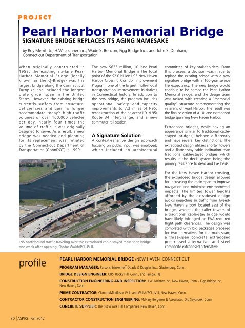
PROJECT<strong>Pearl</strong> <strong>Harbor</strong> <strong>Memorial</strong> <strong>Bridge</strong>SIGNATURE BRIDGE REPLACES ITS AGING NAMESAKEby Roy Merritt Jr., H.W. Lochner Inc.; Wade S. Bonzon, Figg <strong>Bridge</strong> Inc.; and John S. Dunham,Connecticut Department of TransportationWhen originally constructed in1958, the existing six-lane <strong>Pearl</strong><strong>Harbor</strong> <strong>Memorial</strong> <strong>Bridge</strong> (locallyknown as the Q-<strong>Bridge</strong>) was thelargest bridge along the ConnecticutTurnpike and included the longestplate girder span in the UnitedStates. However, the existing bridgecurrently suffers from structuraldeficiencies and can no longeraccommodate today’s high-trafficvolumes of over 160,000 vehiclesper day, nearly four times thevolume of traffic it was originallydesigned to serve. As a result, a newbridge was needed and planningfor its replacement was initiatedby the Connecticut Department ofTransportation (ConnDOT) in 1990.<strong>The</strong> new $635 million, 10-lane <strong>Pearl</strong><strong>Harbor</strong> <strong>Memorial</strong> <strong>Bridge</strong> is the focalpoint of the $2.0 billion I-95 New Haven<strong>Harbor</strong> Crossing Corridor ImprovementProgram, one of the largest multi-modaltransportation improvement initiativesin Connecticut history. In addition tothe new bridge, the program includesoperational, safety, and capacityimprovements to 7.2 miles of I-95,reconstruction of the adjacent I-91/I-95/Route 34 Interchange, and a newcommuter rail station.A Signature SolutionA context-sensitive design approachfocusing on public input was employed,which included an architecturalcommittee of key stakeholders. Fromthis process, a decision was made toreplace the existing bridge with a newsignature bridge with a 100-year servicelife expectancy. <strong>The</strong> new bridge wouldcontinue to be named the <strong>Pearl</strong> <strong>Harbor</strong><strong>Memorial</strong> <strong>Bridge</strong>, and the design teamwas tasked with creating a “memorialquality” structure commemorating theveterans of <strong>Pearl</strong> <strong>Harbor</strong>. <strong>The</strong> result wasthe final selection of a 10-lane extradosedbridge spanning New Haven <strong>Harbor</strong>.Extradosed bridges, while having anappearance similar to traditional cablestayedbridges, behave differentlyand have several key distinctions. <strong>The</strong>extradosed design utilizes shorter towersand a flatter stay-cable inclination thantraditional cable-stayed bridges, whichresults in the deck system being theprimary resistance to dead and live loads.I-95 northbound traffic traveling over the extradosed cable-stayed main-span bridge,one week after opening. Photo: Walsh/PCL JV II.For the New Haven <strong>Harbor</strong> crossing,the extradosed bridge design allowedfor increasing the main span to improvenavigation and minimize environmentalimpacts. <strong>The</strong> limited tower heightsafforded by the extradosed designavoids impacting air traffic from Tweed-New Haven airport located east of thebridge, whereas the taller towers ofa traditional cable-stay bridge wouldhave likely infringed on FAA-requiredflight path clearances. <strong>The</strong> design wascompleted with bid packages preparedfor two alternatives for the main span;a three-span concrete extradosedprestressed alternative, and steelcomposite extradosed alternative.profilePEARL HARBOR MEMORIAL BRIDGE /NEW HAVEN, CONNECTICUTProgram Manager: Parsons Brinkerhoff Quade & Douglas Inc., Glastonbury, Conn.BRIDGE DESIGN ENGINEER: URS, Rocky Hill, Conn., and Tampa, Fla.CONSTRUCTION ENGINEERING AND INSPECTION: H.W. Lochner Inc., New Haven, Conn. / Figg <strong>Bridge</strong> Inc.,New Haven, Conn.PRIME CONTRACTOR: Cianbro/Middlesex JV III and Walsh/PCL JV II, New Haven, Conn.CONTRACTOR CONSTRUCTION ENGINEERING: McNary Bergeron & Associates, Old Saybrook, Conn.CONCRETE SUPPLIER: <strong>The</strong> Suzio York Hill Companies, New Haven, Conn.30 | ASPIRE, Fall 2012
Typical cross section, cast-in-place segmental main span unit. Drawing: Lochner/FIGG.<strong>The</strong> bidding process resulted inconstruction of the concrete extradosedprestressed concrete alternate, whichbegan in April 2008, with constructionof the northbound in-waterfoundations. <strong>The</strong> northbound bridgewas recently completed and openedto traffic in June 2012. It is the firstextradosed bridge constructed in theUnited States. Construction of thesouthbound bridge will occur followingdemolition of the existing bridge andis expected to be open to traffic byNovember 2016.<strong>The</strong> final configuration of thebridge’s harbor crossing consists of a157-m-long (515 ft) main span withadjacent 75.85-m-long (249 ft)approach spans, providing 19.5 m(64 ft) of vertical clearance over theapproximately 73-m-wide (240 ft)navigation channel. Beyond the main308.7-m-long (1013 ft) harbor crossing,approach spans extend 484 m (1588ft) to the west, and another 624 m(2047 ft) to the east, for an overallbridge length of 1417 m (4649 ft).Main Span SuperstructureSegmental construction of the main spansuperstructure was performed utilizing thebalanced-cantilever method with cast-inplaceconcrete segments. <strong>Concrete</strong> boxsegments are typically 4.36 m (14.3 ft)long, range from 29.9 to 33.6 m (98 to110 ft) wide, and have a nominal depthof 3.5 m (11.5 ft) that increases to 5 m(16 ft) at the tower supports. Segmentswere constructed using high-performanceconcrete featuring Type III cement forhigh early strength, a design compressivestrength of 41 MPa (6.0 ksi), and 7%silica fume to decrease permeability. <strong>The</strong>northbound and southbound concretebox-girder segments will each ultimatelycarry five 3.6-m-wide (12 ft) lanes oftraffic, an auxiliary lane varying in width,and two 3.6-m-wide (12 ft) shoulders.During demolition of the existing bridgeand construction of the southboundbridge, the northbound segments willtemporarily carry three lanes of traffic inboth directions.<strong>The</strong> initial concrete segments locatedat the tower piers are referred to as“pier tables,” and contain internaldiaphragms that transfer thesuperstructure loads to disk bearingssupported on the tower pier strutbeams. <strong>The</strong> pier tables were lengthenedto 15.9 m (52 ft) during construction toinclude the first pair of typical segments,creating additional deck area to easeinstallation of form travelers on bothends of the pier table. Four travelerswere employed, allowing for segmentconstruction to advance simultaneouslyin both directions from each tower. <strong>The</strong>54,500 kN (12,300 kip) bearings beneaththe pier tables are the world’s largest diskbearings ever installed on a bridge.Segment post-tensioning consistsof longitudinal cantilever tendons,transverse deck tendons, as well asdraped transverse external tendons atstay-cable locations that are deflectedthrough the two central vertical websof the section. ASTM A416M, Grade1860, low-relaxation strands are utilizedthroughout. <strong>The</strong> four longitudinalcantilever tendons anchoring in thetop slab of both the backspan andmain-span segments were stressedafter segments achieved a strengthof 28 MPa (4 ksi), and varied in sizefrom 17 to 27 strands. Transverse deckpost-tensioning consists of four-strandtendons, typically spaced at 2.18 m (7.2ft). <strong>The</strong> 19-strand draped transverseexternal tendons were provided totransfer superstructure forces to thestay-cables, and were stressed aftercasting the stay diaphragms and prior toinstallation of the stay cables.Stay-Cable System<strong>The</strong> northbound and southbound mainspan superstructures, are each carriedby a series of 64 individual stay cablesConnecticut Department of Transportation, OWNERBRIDGE DESCRIPTION: A three-span extradosed bridge with span lengths of 249, 515, and 249 ft built using the balanced cantilever method ofconstruction with cast-in-place concrete segmentsSTRUCTURAL COMPONENTS: Twin structure each consisting of five cell cast-in-place concrete box segments, 14.3 ft long, 98 to 110 ft wide, and11.5 ft deep supported by 64 stay cablesBRIDGE CONSTRUCTION COST: $635 millionASPIRE, Fall 2012 | 31
<strong>Concrete</strong> was placed for the deck of thepier tables from pump trucks stationedon the temporary access trestle below.Photo: Lochner/FIGG.parallel to each other in a “harp”pattern. <strong>The</strong> stays anchor in pairs tothe edge beams of the cast-in-placeconcrete segments and to the steelanchor boxes within the tower legs.Each stay consists of 48 individual15.2-mm-diameter (0.6 in.), 7-wire,low-relaxation strands up to 66.5 m(218 ft) in length, each greased andencapsulated in a tightly adhered high-Master Chief Richard Iannucci, U.S. Navy,speaks at the dedication ceremony infront of the architectural lettering at theAnchor Pier. Photo: Lochner/FIGG.density polyethylene (HDPE) coating forcorrosion protection during the strandmanufacturing process. <strong>The</strong>se 48 strandsare, in turn, encased in a co-extrudedHDPE sheathing pipe with an outerdiameter of 225 mm (9 in.) that remainsungrouted during its service life.Stay-cable strand installation wasperformed using the elongation methodto control variations in individualstrand force, and then stressed to 60%maximum ultimate tensile strength(MUTS) from within the tower anchorboxes using monostrand jacks. <strong>The</strong>60% MUTS limit for the cable strandsis higher for the extrodosed bridgedesign than in conventional cablestayedbridges, which utilize an upperstress limit of 45% MUTS. Because ofthe geometric layout of the stay-cablesand the relatively large stiffness of thebox girder superstructure, the stressrange and overall contribution to staycableforce from live loads is significantlyless than that of a typical cable-stayedstructure, therefore justifying the use ofthe higher allowable cable stresses onthe new extradosed bridge.Strand stressing was typically performedin three steps. First, strands wereinstalled and stressed individually to aforce level equivalent to 15% MUTS.This low force level allowed internal“cheeseplate” type strand centeringdamper assemblies to be slid downthe galvanized steel guide pipes neareach anchorage and bolted in their finalposition. <strong>The</strong> second stage of tensioningwas performed to approximately 50%of the final stay-cable force. A final,third stage of strand tensioning wasthen performed to fine-tune the strandforces to closely match the target stayforce value. <strong>The</strong> adjustable anchorageswere then capped and greased.Tower Piers and Anchor Piers<strong>The</strong> main span towers and anchorpiers are founded on a series of2.44-m-diameter (8 ft) drilledshafts and capped by 3.53-m-deep(11.6 ft) rectangular footings. Eachpier features three legs with heightsup to 45.1 m (148.0 ft), with ahorizontal strut beam supported byan intermediate column. <strong>The</strong> strutbeam spans between tower legs tosupport the superstructure segments.Anchor piers at each end of the mainspanunit feature cast-in architecturallettering with gold leaf inlay in amanner consistent with the bridge’smonumental aesthetic theme. <strong>The</strong>vertical tower legs and columns havea hollow, oval shape reminiscentof the smoke stacks of a ship. <strong>The</strong>main span unit’s structural scheme isunique in that stay-cables for boththe northbound and southboundsuperstructures anchor in the sharedmiddle leg of the tower piers.<strong>The</strong> new northbound extradosed cable-stayed, main-span bridge crosses the QuinnipiacRiver directly adjacent to the existing Q-<strong>Bridge</strong>. Photo: Lochner/FIGG.All portions of the towers weredesignated as mass concrete, with a41 MPa (6.0 ksi) mix design employedusing slag cement at 75% of thetotal cementitious materials originallyspecified in order to control internalcuring temperatures. <strong>The</strong> jump form32 | ASPIRE, Fall 2012
AESTHETICSCOMMENTARYby Frederick GottemoellerIt’s always exciting when a new (to the United States) bridge type arrives on the scene. <strong>The</strong> Sunshine Skyway started aperiod of innovation and experimentation that led, in subsequent decades, to the construction of a number of outstandingcable-stayed bridges in the United States. <strong>The</strong> <strong>Pearl</strong> <strong>Harbor</strong> <strong>Memorial</strong> <strong>Bridge</strong> will do the same.As with the new cable-stayed bridges, a key issue will be the appropriate shape for the towers. However, the girder isalso an important feature in extradosed bridges, more so than the deck of a cable-stayed bridge. Designers will have toincorporate the appropriate size and shape of the girder. Striking a good visual balance between the girder and the towersis the key to success.<strong>The</strong> first part of the <strong>Pearl</strong> <strong>Harbor</strong> <strong>Bridge</strong> to be constructed, the northbound half, is sandwiched between the old bridge and a massive liftbridge. At this stage, it is hard to evaluate all of the facets of the design, but it is clear already that the designers have achieved a good visualrelationship between the visual mass of the towers and the visual mass of the girders. <strong>The</strong> simple oval cylinders of the towers are visuallystrong shapes that make clear their central role in the support of the bridge. <strong>The</strong> sloped outside webs of the girders minimize their visualmass, so that they don’t overwhelm the towers. Meanwhile, the slight haunch at the piers makes clear that the girders play a major role in thesupport of the deck.<strong>The</strong>re were additional reasons to make the towers strong, simple shapes. <strong>The</strong> towers need to hold their own against the towers of the adjacentlift bridge, against the tanks and towers of the surrounding industrial landscape, and the sheer width and length of their own bridge deck.<strong>The</strong> visual strength of their shapes allows them to assert their importance in the scene.Finally, the exposed stay anchorages along the edges of the girder create a repetitive rhythm of smaller elements and give the bridge somedetails that relate its scale to its neighbors. <strong>The</strong>y also make clear how the bridge works by drawing the eye to the point where loads are transferredfrom the girders to the stays and thence to the towers.Extradosed bridges are now on the drawing boards and a few are under construction. It will be interesting to see how designers address thisbridge type’s aesthetic challenges.system was coated with spray-on foamto insulate the surface concrete andmaintain internal thermal gradientsbelow the required 20°C (68°F).Internal concrete temperatures weremonitored hourly during curingusing an automated sensor systemthat communicated wirelessly with adedicated internet-accessible computer.A Grand OpeningOn Friday, June 22, 2012, a ribboncutting ceremony was held to celebratethe completion and opening of thenorthbound extradosed bridge.<strong>The</strong> ceremony was highlightedby a Ceremonial Veterans WreathDedication with four survivingveterans of the attacks on <strong>Pearl</strong><strong>Harbor</strong>, a ceremonial ribbon cutting,and speeches from local politicalleaders, FHWA, and the U.S. Navy.Approximately 250 members of thepublic attended.Overnight, following the ceremony,work was completed on the approachroadway temporary crossovers andthe new northbound bridge openedsuccessfully to traffic, Saturday morning,June 23, 2012.Tower leg jump-form systems were sprayed with insulating foam to control thermalgradients during mass concrete curing. Photo: Lochner/FIGG.Roy Merritt Jr., is a senior structuralengineer with H.W. Lochner Inc. inNew Haven, Conn.; Wade S. Bonzon isan assistant resident engineer with Figg<strong>Bridge</strong> Inc. in New Haven, Conn.; and JohnS. Dunham is supervising engineer - <strong>Pearl</strong><strong>Harbor</strong> <strong>Memorial</strong> <strong>Bridge</strong> with ConnecticutDepartment of Transportation inNewington, Conn.For additional photographs orinformation on this or other projects,visit www.aspirebridge.org and openCurrent Issue.ASPIRE, Fall 2012 | 33


