

Hoover Dam Bypass - Aspire - The Concrete Bridge Magazine
Hoover Dam Bypass - Aspire - The Concrete Bridge Magazine
Hoover Dam Bypass - Aspire - The Concrete Bridge Magazine

You also want an ePaper? Increase the reach of your titles
YUMPU automatically turns print PDFs into web optimized ePapers that Google loves.
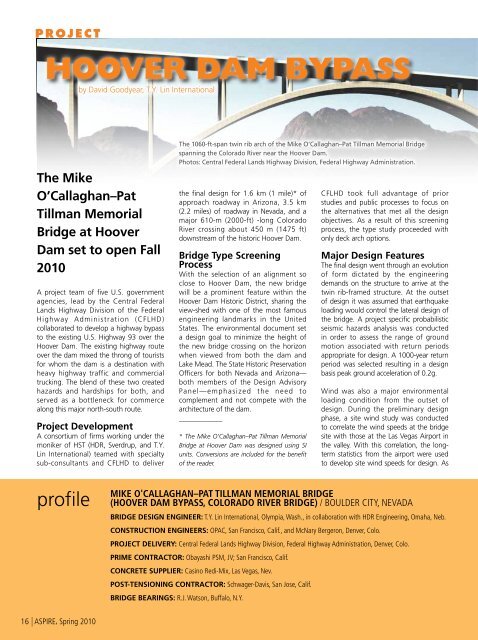
P R O J E C Thoover dam bypassby David Goodyear, T.Y. Lin International<strong>The</strong> MikeO’Callaghan–PatTillman Memorial<strong>Bridge</strong> at <strong>Hoover</strong><strong>Dam</strong> set to open Fall2010A project team of five U.S. governmentagencies, lead by the Central FederalLands Highway Division of the FederalHighway Administration (CFLHD)collaborated to develop a highway bypassto the existing U.S. Highway 93 over the<strong>Hoover</strong> <strong>Dam</strong>. <strong>The</strong> existing highway routeover the dam mixed the throng of touristsfor whom the dam is a destination withheavy highway traffic and commercialtrucking. <strong>The</strong> blend of these two createdhazards and hardships for both, andserved as a bottleneck for commercealong this major north-south route.Project DevelopmentA consortium of firms working under themoniker of HST (HDR, Sverdrup, and T.Y.Lin International) teamed with specialtysub-consultants and CFLHD to deliver<strong>The</strong> 1060-ft-span twin rib arch of the Mike O’Callaghan–Pat Tillman Memorial <strong>Bridge</strong>spanning the Colorado River near the <strong>Hoover</strong> <strong>Dam</strong>.Photos: Central Federal Lands Highway Division, Federal Highway Administration.the final design for 1.6 km (1 mile)* ofapproach roadway in Arizona, 3.5 km(2.2 miles) of roadway in Nevada, and amajor 610-m (2000-ft) -long ColoradoRiver crossing about 450 m (1475 ft)downstream of the historic <strong>Hoover</strong> <strong>Dam</strong>.<strong>Bridge</strong> Type ScreeningProcessWith the selection of an alignment soclose to <strong>Hoover</strong> <strong>Dam</strong>, the new bridgewill be a prominent feature within the<strong>Hoover</strong> <strong>Dam</strong> Historic District, sharing theview-shed with one of the most famousengineering landmarks in the UnitedStates. <strong>The</strong> environmental document seta design goal to minimize the height ofthe new bridge crossing on the horizonwhen viewed from both the dam andLake Mead. <strong>The</strong> State Historic PreservationOfficers for both Nevada and Arizona—both members of the Design AdvisoryPanel—emphasized the need tocomplement and not compete with thearchitecture of the dam.____________* <strong>The</strong> Mike O’Callaghan–Pat Tillman Memorial<strong>Bridge</strong> at <strong>Hoover</strong> <strong>Dam</strong> was designed using SIunits. Conversions are included for the benefitof the reader.CFLHD took full advantage of priorstudies and public processes to focus onthe alternatives that met all the designobjectives. As a result of this screeningprocess, the type study proceeded withonly deck arch options.Major Design Features<strong>The</strong> final design went through an evolutionof form dictated by the engineeringdemands on the structure to arrive at thetwin rib-framed structure. At the outsetof design it was assumed that earthquakeloading would control the lateral design ofthe bridge. A project specific probabilisticseismic hazards analysis was conductedin order to assess the range of groundmotion associated with return periodsappropriate for design. A 1000-year returnperiod was selected resulting in a designbasis peak ground acceleration of 0.2g.Wind was also a major environmentalloading condition from the outset ofdesign. During the preliminary designphase, a site wind study was conductedto correlate the wind speeds at the bridgesite with those at the Las Vegas Airport inthe valley. With this correlation, the longtermstatistics from the airport were usedto develop site wind speeds for design. Asprofilemike o'callaghan–pat tillman memorial bridge(hoover dam bypass, colorado river bridge) / boulder city, NEVADAbridge design ENGINEER: T.Y. Lin International, Olympia, Wash., in collaboration with HDR Engineering, Omaha, Neb.construction ENGINEERs: OPAC, San Francisco, Calif., and McNary Bergeron, Denver, Colo.project delivery: Central Federal Lands Highway Division, Federal Highway Administration, Denver, Colo.PRIME CONTRACTOR: Obayashi PSM, JV; San Francisco, Calif.concrete supplier: Casino Redi-Mix, Las Vegas, Nev.POST-TENSIONING CONTRACTOR: Schwager-Davis, San Jose, Calif.bridge bearings: R.J. Watson, Buffalo, N.Y.16 | ASPIRE, Spring 2010
A consortium offirms teamed withspecialty subconsultantsand CentralFederal Lands HighwayDivision to deliver thefinal design.a result, the 3-second wind speed of 56 m/sec (125 mph) was used. Dynamic studiesresulted in a gust loading factor of 2.4,which collectively resulted in wind controllingthe design for lateral forces. <strong>The</strong>refore, theensuing design for seismic resistance wasbased on essentially elastic criteria.Arch Framing<strong>The</strong> 1060-ft-span, 70 MPa (10,100 psi)concrete arch is an efficient element forgravity loads in its final form. <strong>The</strong>re weretwo aspects of design that resulted intwin ribs instead of a typical single boxsection for this arch. <strong>The</strong> first is one ofpractical construction. A single box wouldbe almost 20 m (66 ft) wide, and weighapproximately 30 metric tons/m (20 kip/ft).This section size would rule out a precastsegmental option.<strong>The</strong> second aspect is the matter ofperformance under extreme lateral forces.At the time the framing plan was devised,the level of seismic ground motion had notbeen determined. A single arch rib wouldleave no opportunity for tuning stiffness orfor providing for frame ductility, whereastwin ribs could provide an excellent meansof creating ductile Vierendeel links thatcould otherwise fully protect the gravitysystem of the arch.Spandrel FramingT h e c o m p o s i t e s t e e l - c o n c r e t esuperstructure was selected for speedFollowing closure of the arch, the spandrel columns were set using the high-line crane.Superstructure girders are shown being erected.of erection and to reduce the weight onthe arch. <strong>The</strong> spacing of spandrels wasan extension of the concept to erect thebridge using a highline (tramway) cranesystem. Above 100 kips, there is a jumpin highline cost, so the decision was madeto target a 100 kip maximum weight formajor superstructure elements. <strong>The</strong> spanwas set in the range that a high-line cranecould deliver the steel box sections, whichresulted in a nominal 37-m (121-ft) span.This span also allows steel girders to beset within the range of most conventionalcranes, if an alternative erection systemhad been selected. <strong>The</strong> statical systemincludes sliding bearings for the short, stiffpiers over the arch crown, and similar piersnear the abutments. This was necessarydue to the large secondary momentsdeveloped in these piers from creepdeflections of the arch, and also produceda more even distribution of longitudinalseismic forces among the piers.Pier Cap FramingIntegral concrete pier caps were selectedover steel box cap sections. <strong>The</strong>seprovided lateral bracing of the spandrelcolumns and ultimate stability to theflexible columns in the longitudinaldirection. <strong>Concrete</strong> was selected oversteel due to the higher maintenance andinspection costs associated with fracturecritical steel diaphragms, even thoughsteel caps might have a lower first cost.Open Spandrel CrownAn open spandrel crown was selectedover the option of an integral crown.A special consideration was that theCAST-IN-PLACE CONCRETE SEGMENTAL ARCH WITH PRECAST CONCRETE SEGMENTAL COLUMNS / NEVADA ANDARIZONA DEPARTMENTS OF TRANSPORTATION, OWNERSREINFORCement SUPPLIER: Harris Rebar, Phoenix, Ariz.form traveler: NRS, Bangkok, ThailandBRIDGE DESCRIPTION: A 1900-ft-long bridge over the Colorado River at <strong>Hoover</strong> <strong>Dam</strong>, with a 1060-ft-long concrete arch main span, up to 302-ft-tallprecast concrete segmental columns, and cast-in-place concrete deck.structural components: <strong>The</strong> arch is a twin rib hollow box section with Vierendeel struts connecting the twin ribs. Columns are twin precastconcrete segmental box structures. <strong>The</strong> roadway deck is a steel-concrete composite box girder frame with integral post-tensioned, cast-in-place concretepier caps.BRIDGE CONSTRUCTION COST: $114 millionASPIRE, Spring 2010 | 17
the typical approach could provecounterproductive in several respects. Asubstantial length of time for reviewingand approving an erection scheme mightdelay the project. <strong>The</strong> managementteam also believed that more informedbids could be developed if there was amore complete erection scheme shownwith the plans. <strong>The</strong>refore, the decisionwas made to show a complete erectionscheme for dead load on the plans andallow the contractors to use that schemeor their own.This is a typical section through the twin-ribarch and roadway showing the piers andintegral pier cap.composite steel deck would resultin a very abrupt, mechanical lookingconnection with an integral crown.Equally significant was the high rise of thearch. When studied in either concrete orsteel, an integral crown solution lookedblocky and massive at the crown, andran counter to the architectural goal oflightness and openness when viewedfrom Lake Mead.Cross Section Forms<strong>The</strong> height of the tallest taperedspandrel columns is almost 92 m (302ft). Wind studies included considerationsof drag and vortex shedding on themain structural sections exposed tothe long canyon fetch from over LakeMead. Studies showed that substantialadvantage could be gained both in termsof vibration and drag by chamfering thecorners of both the columns and thearch. While this adds somewhat to thecomplexity of construction, the benefit interms of reduced demand and materialsavings were substantial.Construction MethodsAs with any large bridge structure, thedead load design is dominated by theassumptions of a construction scheme.<strong>The</strong> typical approach in the United Statesis to select an erection scheme, but toshow it in the plans only schematically,and defer responsibility for both thescheme and the details to the contractor.<strong>The</strong> design management team decidedthat this structure was so unique thatBoth precast and cast-in-place concretemethods were permitted for the archand spandrel columns. <strong>The</strong> contract waswritten to allow alternative methods oferection, however the columns acrossthe entire bridge were to be of a singletype (precast or cast in place) in orderto conform to the time-dependentassumptions inherent in design.Construction<strong>The</strong> first challenge for the constructionteam was creating a foothold forfoundation construction. Climbing onthe side of the cliff 800 ft over the riverbelow was difficult enough, but excavating(and doing so within the loss limits in thespecification) was an incredible challenge.<strong>The</strong> subcontractor who met this challengewas Ladd Construction from Redding, Calif.<strong>The</strong>y not only met the tight schedule forthis work, but completed the excavationallowing about half of the rockfall into theriver that was permitted.Initial bridge construction began withfooting and abutment work, and in theprecast yard outside of Boulder City wherethe contractor set up their own facility toprecast the columns. Column segmentswere trucked to the site as needed forerection, and set into place using both thehigh-line crane and conventional craneslocated at the highway hairpin in Nevada.<strong>The</strong> first precast pier segment, supported bythe high-line crane is erected on its footing.Four form traveler headings were operatedin concert for the cast-in-place concretearch. After an initial learning curve, thecontractor reached a reliable cycle of2 weeks, and often exceeded that onsegments that did not contain a temporarystay for erection.<strong>The</strong> arch was closed in August 2009within an impressive ¾-in. toleranceat closure. Spandrel columns wereerected using the high-line crane, andsuperstructure girders continue to be set.<strong>The</strong> bridge is scheduled for opening in theFall 2010.____________David Goodyear is senior vice president atT.Y. Lin International, Olympia, Wash.Progress on construction and additionalbackground can be viewed online atwww.hooverdambypass.org.<strong>The</strong> tallest ofthe tapered spandrelcolumns is almost 92 m(302 ft) tall.An illustration to show the use of cable stays to construct the arch segments and theposition of the high-line crane.18 | ASPIRE, Spring 2010


