Vanguard 3400 Series Installation Manual - Vanguard Networks
Vanguard 3400 Series Installation Manual - Vanguard Networks
Vanguard 3400 Series Installation Manual - Vanguard Networks

Create successful ePaper yourself
Turn your PDF publications into a flip-book with our unique Google optimized e-Paper software.
<strong>Vanguard</strong> <strong>3400</strong> <strong>Series</strong><br />
<strong>Installation</strong> <strong>Manual</strong>
Notice<br />
©Copyright © 2007 <strong>Vanguard</strong> <strong>Networks</strong>. All rights reserved.<br />
25 Forbes Boulevard<br />
Foxboro, Massachusetts 02035<br />
+1 (508) 964-6200<br />
All rights reserved<br />
Printed in U.S.A.<br />
Restricted Rights Notification for U.S. Government Users<br />
The software (including firmware) addressed in this manual is a "commercial item" as that<br />
term is defined in 48 C.F.R. 2.101, consisting of "commercial computer software" and "commercial<br />
computer software documentation" as such terms are used in 48 C.F.R. 12.212. Consistent<br />
with 48 C.F.R. 12.212 and 48 C.F.R. 227-7202-1 through 227-7202-4, and their<br />
successors as applicable, Customer will provide the Software and/or software documentation<br />
to U.S. Government End Users only pursuant to the terms and conditions therein.<br />
Unpublished - rights reserved under the copyright laws of the United States.
Notice (continued)<br />
Proprietary Material<br />
Information and software in this document are proprietary to <strong>Vanguard</strong> <strong>Networks</strong> (or its<br />
Suppliers) and without the express prior permission of an officer of <strong>Vanguard</strong> Managed Solutions<br />
may not be copied, reproduced, disclosed to others, published, or used, in whole or in<br />
part, for any purpose other than that for which it is being made available. Use of software<br />
described in this document is subject to the terms and conditions of the Software License<br />
Agreement.<br />
This document is for information purposes only and is subject to change without notice.<br />
Radio Frequency Interference Regulations<br />
This equipment has been tested and found to comply with the limits for a Class A digital<br />
device, pursuant to Part 15 of the FCC Rules. These limits are designed to provide reasonable<br />
protection against interference when the equipment is operated in a commercial environment.<br />
This equipment generates, uses, and can radiate radio frequency energy and, if not installed<br />
and used in accordance with the instruction manual, may cause harmful interference to radio<br />
communications.<br />
Changes or modifications not expressly approved by <strong>Vanguard</strong> <strong>Networks</strong> could void the<br />
user's authority to operate the equipment.<br />
This Class A digital apparatus meets all requirements of the Canadian Interference-Causing<br />
Equipment Regulations.<br />
This is a Class A product. Operation of this equipment in a residential environment may<br />
cause radio interference, in which case the user may be required to take adequate measures to<br />
correct the interference at his/her own expense.<br />
This product was verified under test conditions that included use of shielded DCE cable(s),<br />
and shielded Ethernet cables. Use of different cables will invalidate verification and increase<br />
the risk of causing interference to radio and TV reception.<br />
You can obtain the proper cables from <strong>Vanguard</strong> <strong>Networks</strong>.<br />
Telecommunications Regulations<br />
Equipment that complies with Part 68 of the FCC rules includes a label or permanent<br />
marking on the printed circuit board that connects to the network that contains, among other<br />
information, the FCC registration number and ringer equivalence number (REN) for this<br />
equipment. If requested, this information must be provided to the telephone company. A plug<br />
and jack used to connect this equipment to the premises wiring and telephone network must<br />
comply with the applicable FCC Part 68 rules and requirements adopted by the ACTA.<br />
The REN is used to determine the number of devices that may be connected to a telephone<br />
line. Excessive RENs on a telephone line may result in the devices not ringing in response to<br />
an incoming call. In most but not all areas, the sum of RENs should not exceed five (5.0). To<br />
be certain of the number of devices that may be connected to a line, as determined by the total
RENs, contact the local telephone company. The REN for this product is part of the product<br />
identifier that has the format US:AAAEQ##TXXXX. The digits represented by ## are the<br />
REN without a decimal point (e.g., 03 is a REN of 0.3).<br />
If this equipment causes harm to the telephone network, the telephone company will notify<br />
you in advance that temporary discontinuance of service may be required. But if advance<br />
notice isn't practical, the telephone company will notify the customer as soon as possible.<br />
Also, you will be advised of your right to file a complaint with the FCC if you believe it is<br />
necessary. The telephone company may make changes in its facilities, equipment, operations<br />
or procedures that could affect the operation of the equipment. If this happens the telephone<br />
company will provide advance notice in order for you to make necessary modifications to<br />
maintain uninterrupted service. If the equipment is causing harm to the telephone network,<br />
the telephone company may request that you disconnect the equipment until the problem is<br />
resolved. Connection to party line service is subject to state tariffs. Contact the state public<br />
utility commission, public service commission or corporation commission for information. If<br />
your home has specially wired alarm equipment connected to the telephone line, ensure the<br />
installation of this equipment does not disable your alarm equipment. If you have questions<br />
about what will disable alarm equipment, consult a trained technician.<br />
Equipment that meets the applicable Industry Canada Terminal Equipment Technical<br />
Specifications is conformed by the registration number. Equipment that complies with<br />
Industry rules includes a label or permanent marking on the printed circuit board that<br />
connects to the network. The abbreviation, IC, before the registration number signifies that<br />
the registration was performed based on a Declaration of Conformity indicating that Industry<br />
Canada technical specifications were met. It does not imply that Industry Canada approved<br />
the equipment.<br />
Part No. T0288, Rev C<br />
Publication Code TK<br />
First Printing March 2008<br />
<strong>Manual</strong> is current for Release 7.2 of <strong>Vanguard</strong> Applications Ware.<br />
To comment on this manual, please send e-mail to Michael.Brogan@vanguardnetworks.com
Contents<br />
Special Notices and Translations<br />
Customer Information<br />
Chapter 1<br />
About the <strong>Vanguard</strong> <strong>3400</strong> <strong>Series</strong><br />
Overview ...................................................................................................... 1-1<br />
Features ......................................................................................................... 1-2<br />
Applications .................................................................................................. 1-6<br />
Chapter 2<br />
Hardware Description<br />
Overview ...................................................................................................... 2-1<br />
Enclosure ...................................................................................................... 2-2<br />
Motherboard ................................................................................................. 2-5<br />
<strong>Vanguard</strong> <strong>Networks</strong> Daughtercards .............................................................. 2-9<br />
Chapter 3<br />
<strong>Installation</strong> and Replacement<br />
Overview ....................................................................................................... 3-1<br />
Checking Your Shipment Contents ............................................................... 3-2<br />
Installing The <strong>Vanguard</strong> <strong>3400</strong> <strong>Series</strong>............................................................. 3-3<br />
<strong>Installation</strong>................................................................................................. 3-4<br />
Thermal Considerations ............................................................................ 3-6<br />
Cabling Your <strong>Vanguard</strong> <strong>3400</strong> <strong>Series</strong> ......................................................... 3-7<br />
Cable Adapters and Special Cables ...................................................... 3-8<br />
Cabling Daughtercards ......................................................................... 3-15<br />
Modifying Your <strong>Vanguard</strong> <strong>3400</strong> <strong>Series</strong> ......................................................... 3-17<br />
Accessing the Motherboard....................................................................... 3-18<br />
Installing and Removing the Encryption PCI Mezzanine Card ................ 3-23<br />
Installing/Removing the Lithium Battery ................................................. 3-25<br />
Chapter 4<br />
Powering Up Your <strong>Vanguard</strong> <strong>3400</strong> <strong>Series</strong><br />
Overview ...................................................................................................... 4-1<br />
Power Up Procedure ..................................................................................... 4-2<br />
Loading the Software ................................................................................... 4-3<br />
Appendix A<br />
Specifications<br />
Overview ...................................................................................................... A-1<br />
1
Contents (continued)<br />
Appendix B<br />
Software License and Regulatory Information<br />
Overview ...................................................................................................... B-1<br />
FCC Part 68 and Telephone Company Procedures and Requirements for DSU, T1,<br />
and ISDN Interfaces ................................................................................. B-2<br />
Product Declarations and Regulatory Information ....................................... B-4<br />
Return Procedures<br />
Introduction .................................................................................................. B-1<br />
2
About This <strong>Manual</strong><br />
Overview<br />
Introduction<br />
This installation describes features, hardware, specifications, and applications for the<br />
<strong>Vanguard</strong> <strong>3400</strong> <strong>Series</strong>.<br />
Note<br />
For information on operating system software and configuration, see the<br />
<strong>Vanguard</strong> Basic Configuration <strong>Manual</strong> (Part Number T0113).<br />
Audience This manual is intended for people who install and operate the <strong>Vanguard</strong> <strong>3400</strong><br />
<strong>Series</strong>.<br />
How to Use This<br />
<strong>Manual</strong><br />
The following table describes the contents of this manual:<br />
This Chapter<br />
Chapter 1<br />
Chapter 2<br />
Chapter 3<br />
Chapter 4<br />
Appendix A<br />
Appendix B<br />
Description<br />
<strong>Vanguard</strong> <strong>3400</strong> <strong>Series</strong>’ hardware and software features.<br />
Description of the <strong>Vanguard</strong> <strong>3400</strong> <strong>Series</strong> hardware<br />
features and components.<br />
Installing and replacing <strong>Vanguard</strong> <strong>3400</strong> <strong>Series</strong> hardware<br />
including cards and motherboard.<br />
Powerup procedures and software loading.<br />
Product specifications.<br />
FCC and Telephone Company procedures and<br />
requirements.<br />
3
Special Notices and Translations<br />
Special Notices<br />
The following notices emphasize certain information in the guide. Each serves a<br />
special purpose and is displayed in the format shown:<br />
Note<br />
Note is used to emphasize any significant information.<br />
Caution<br />
Caution provides you with information that, if not followed, can result in damage to<br />
software, hardware, or data.<br />
Warning<br />
Warning is the most serious notice, indicating that you can be physically hurt.<br />
Simplified Chinese<br />
Danish<br />
Særlige<br />
overskrifter<br />
Følgende overskrifter fremhæver nogle af oplysningerne i vejledningen. De tjener<br />
hvert et specifikt formål og vises i følgende format:<br />
Bemærk<br />
Bemærk anvendes til at fremhæve vigtig information.<br />
Forsigtig<br />
Forsigtig understreger oplysninger, som, hvis de ikke bliver fulgt, kan føre til<br />
beskadigelse af software, hardware eller data.<br />
Advarsel<br />
Advarsel er den mest alvorlige overskrift, og tilkendegiver mulig personskade.<br />
v
Dutch<br />
Bijzondere<br />
vermeldingen<br />
De volgende vermeldingen besteden extra aandacht aan bepaalde informatie in<br />
de handleiding. Elke vermelding heeft een eigen nut en wordt in de volgende<br />
opmaak weergegeven:<br />
Opmerking<br />
Een opmerking wordt gebruikt om belangrijke informatie te benadrukken.<br />
Let op<br />
Dit kopje geeft aan dat u de beschreven instructies moet volgen om schade aan<br />
de software, hardware of gegevens te vermijden.<br />
Waarschuwing<br />
Een waarschuwing is de belangrijkste vermelding. Indien u deze niet volgt, kan<br />
dit tot lichamelijke verwondingen leiden.<br />
Finnish<br />
Erityisilmoitukset<br />
Seuraavat ilmoitukset korostavat tiettyjä oppaan tietoja. Kullakin on oma<br />
erikoistarkoituksensa ja ne esitetään seuraavassa muodossa:<br />
Huomaa<br />
Huomautusta käytetään korostamaan tärkeätä tietoa.<br />
Vaara<br />
Vaarailmoitus antaa tietoa, jonka huomiotta jättäminen voi johtaa ohjelmiston,<br />
laitteiston tai tietojen vahingoittumiseen.<br />
Varoitus<br />
Varoitus on kaikkein vakavin ilmoitus ja se kertoo mahdollisesta<br />
loukkaantumisriskistä.<br />
French<br />
Messages<br />
spéciaux<br />
Les messages suivants mettent en valeur certaines informations dans le guide.<br />
Chacun d’eux remplit une fonction spéciale et est affiché dans le format indiqué :<br />
Important<br />
Important est utilisé pour souligner des informations critiques au sujet d’une<br />
procédure.<br />
Mise en Garde<br />
Une mise en garde vous fournit des informations qui, si elles ne sont pas observées,<br />
peuvent se traduire par des dommages pour le logiciel, le matériel ou les données.<br />
vi
Avertissement<br />
Un avertissement constitue le message le plus sérieux, indiquant que vous pouvez<br />
subir des blessures corporelles.<br />
German<br />
Besondere<br />
Hinweise<br />
Durch die folgenden Hinweise werden bestimmte Informationen in diesem<br />
Handbuch hervorgehoben. Jeder Hinweis dient einem bestimmten Zweck und<br />
wird im dargestellten Format angezeigt:<br />
Wichtig<br />
WICHTIG wird zur Betonung signifikanter Angaben zu Vorgehensweisen<br />
verwendet.<br />
Vorsicht<br />
Ein Vorsichtshinweis macht Sie darauf aufmerksam, daß Nichtbefolgung zu<br />
Software-, Hardware- oder Datenschäden führen kann.<br />
Warnung<br />
Eine Warnung weist Sie darauf hin, daß ernsthafte Körperverletzungsgefahr besteht.<br />
Italian<br />
Simboli speciali<br />
I seguenti simboli, ciascuno con una speciale funzione, evidenziano determinate<br />
informazioni all’interno del manuale. Il formato è quello riportato qui di seguito.<br />
Nota<br />
Questo tipo di avvertimento viene utilizzato per evidenziare tutte le informazioni<br />
significative relative ad una procedura.<br />
Attenzione<br />
Questo tipo di avvertimento fornisce informazioni che, se non vengono seguite,<br />
possono provocare danni al software, all’hardware o ai dati.<br />
Avvertenza<br />
Questo tipo di avvertimento indica la presenza di condizioni di rischio che<br />
possono causare lesioni fisiche. Si tratta del simbolo più importante al quale<br />
prestare attenzione.<br />
vii
Japanese<br />
Korean<br />
Norwegian<br />
Spesielle<br />
merknader<br />
Merknadstypene nedenfor representerer en bestemt type informasjon i håndboken.<br />
Hver merknadstype har en spesiell hensikt og vises på følgende format:<br />
Merk<br />
Merk brukes for å fremheve viktig informasjon.<br />
Forsiktig<br />
Forsiktig gir deg informasjon om situasjoner som kan føre til skade på programvare,<br />
datamaskin eller data dersom den blir fulgt.<br />
Advarsel<br />
Advarsel er den mest alvorlige merknaden og indikerer at du kan bli fysisk skadet.<br />
viii
Portuguese/<br />
Portugal<br />
Avisos Especiais<br />
Os avisos que se seguem realçam certas informações neste guia. Cada um deles serve<br />
um objectivo especial e é visualizado no formato apresentado:<br />
Nota<br />
Nota é utilizado para realçar qualquer informação importante.<br />
Atenção<br />
Atenção faculta-lhe informações que, se não forem cumpridas, poderão provocar<br />
danos no software, hardware ou nos dados.<br />
Cuidado<br />
Cuidado constitui o aviso mais grave, o qual indica que poderá ficar<br />
fisicamente ferido.<br />
Spanish/Spain<br />
Notificaciones<br />
especiales<br />
Las siguientes notificaciones ponen énfasis sobre determinada información de la<br />
guía. Todas tienen un propósito especial y se muestran con el formato siguiente:<br />
Nota<br />
Las notas se utilizan para destacar determinada información de importancia.<br />
Advertencia<br />
Las advertencias le proporcionan información que debe seguirse, si no desea que el<br />
software, el hardware o los datos puedan verse dañados.<br />
Aviso<br />
Los avisos son las notificaciones de carácter más importante e indican la posibilidad<br />
de daños físicos para el usuario.<br />
Swedish<br />
Speciella<br />
beteckningar<br />
Följande beteckningar betonar viss information i handboken. Var och en har ett<br />
speciellt syfte och visas i formatet nedan:<br />
OBS!<br />
OBS! används för att betona viktig information.<br />
Viktigt<br />
Viktigt ger dig information som, om den inte följs, kan resultera i skada i<br />
programvara, maskinvara eller data.<br />
ix
Varning<br />
Varning är den mest allvarliga beteckningen och den indikerar att du kan<br />
skadas fysiskt.<br />
x
Customer Information<br />
Customer<br />
Questions<br />
Comments About<br />
This <strong>Manual</strong><br />
Customers who have questions about <strong>Vanguard</strong> <strong>Networks</strong> products or services<br />
should contact your <strong>Vanguard</strong> <strong>Networks</strong> representative or visit this website for<br />
product, sales, support, documentation, or training information:<br />
http://www.vanguardnetworks.com/<br />
To help us improve our product documentation, please complete the comment card<br />
included with this manual and return it by fax to (508) 543-0237. If you prefer,<br />
provide your name, company, and telephone number, and someone in the<br />
documentation group will contact you to discuss your comments.<br />
Customer Information xi
Customer Response Card<br />
<strong>Vanguard</strong> <strong>Networks</strong> would like your help in improving its product documentation. Please complete and<br />
return this card by fax to (508) 543-0237; Attention: Product Documentaton, to provide your feedback.<br />
To discuss comments with a member of the documentation group, provide telephone information at the<br />
bottom of this page. Thank you for your help.<br />
Name _________________________________________________________________________<br />
Company Name _________________________________________________________________<br />
Address _______________________________________________________________________<br />
_______________________________________________________________________<br />
_______________________________________________________________________<br />
Document Title: <strong>Vanguard</strong> <strong>3400</strong> <strong>Series</strong> <strong>Installation</strong> <strong>Manual</strong><br />
Part Number:<br />
Please rate this document for usability:<br />
Excellent Good Average Below Average Poor<br />
What did you like about the document? ______________________________________________<br />
______________________________________________________________________________<br />
______________________________________________________________________________<br />
______________________________________________________________________________<br />
______________________________________________________________________________<br />
What information, if any, is missing from the document? _________________________________<br />
______________________________________________________________________________<br />
______________________________________________________________________________<br />
______________________________________________________________________________<br />
______________________________________________________________________________<br />
Cut Here<br />
Please identify any sections/concepts that are unclear or explained inadequately.<br />
______________________________________________________________________________<br />
______________________________________________________________________________<br />
______________________________________________________________________________<br />
______________________________________________________________________________<br />
Additional comments/suggestions. __________________________________________________<br />
______________________________________________________________________________<br />
______________________________________________________________________________<br />
______________________________________________________________________________<br />
______________________________________________________________________________<br />
Telephone ________________________ Ext. _________________ Best time to call __________
Chapter 1<br />
About the <strong>Vanguard</strong> <strong>3400</strong> <strong>Series</strong><br />
Overview<br />
Description<br />
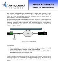
The <strong>Vanguard</strong> <strong>3400</strong> <strong>Series</strong> Standalone Routers, supporting up to two daughtercard<br />
slots, provide wide area network (WAN) access for service providers and enterprise<br />
applications.<br />
Figure 1-1. <strong>Vanguard</strong> <strong>3400</strong> <strong>Series</strong><br />
For a detailed description of the <strong>Vanguard</strong> <strong>3400</strong> <strong>Series</strong> and its features, refer to the<br />
“Features” section on page 1-2.<br />
For descriptions of the <strong>Vanguard</strong> <strong>3400</strong> <strong>Series</strong> Daughtercards and other hardware<br />
components, refer to the appropriate sections in Chapter 2, Hardware Description.<br />
About the <strong>Vanguard</strong> <strong>3400</strong> <strong>Series</strong> 1-1
Features<br />
Features<br />
Introduction This section summarizes the features available with your <strong>Vanguard</strong> 3410/3460/3480.<br />
For descriptions of the software running on your <strong>Vanguard</strong> 3410/3460/3480, refer to<br />
the appropriate protocol document.<br />
This table lists the hardware features of the <strong>Vanguard</strong> <strong>3400</strong> <strong>Series</strong>:<br />
Hardware Features<br />
Product<br />
Target<br />
VG 3410<br />
Small Branch FSP<br />
Data Only<br />
VG 3460<br />
Small Branch<br />
IPT Gateway<br />
VG 3480<br />
Small Branch<br />
IPT Gateway<br />
Memory 64 MB SDRAM 64 MB SDRAM 64 MB SDRAM<br />
OnBoard Flash 16 MB 16 MB 16 MB<br />
Compact Flash N N N<br />
Form Factor Modular Modular Modular<br />
Daughter Card Slots 1 2 2<br />
Mini PCI Card Slots 1 1 1<br />
Ethernet Ports (Total)<br />
10BaseT<br />
10/100BT<br />
10/100/1000BT<br />
Serial Ports<br />
MB Serial Ports<br />
CTP<br />
DC Serial Ports<br />
V.34/V.90 Ports<br />
2<br />
--<br />
2<br />
--<br />
1<br />
1 (RS232)<br />
1x<br />
0<br />
2<br />
--<br />
2<br />
--<br />
4<br />
1 (Universal)<br />
1x<br />
3<br />
DSU Ports 1 2 2<br />
ISDN (S/T & U) Ports 0 2 2<br />
FT1/FE1 Ports<br />
T1/E1/PRI Ports<br />
0<br />
1<br />
0<br />
2<br />
E1 PRI channel density<br />
limited to 46<br />
N<br />
0<br />
N<br />
0<br />
0<br />
8<br />
8<br />
4<br />
8<br />
2<br />
ATM Ports<br />
DS3/E3<br />
N<br />
0<br />
Digital Voice<br />
N<br />
T1/E1 Channels 0<br />
T1/E1 Ports<br />
0<br />
Analog Voice Ports 0<br />
FXS Ports<br />
0<br />
E&M Ports<br />
0<br />
FXO Ports<br />
0<br />
BRI-Voice Ports 0<br />
(ISDN)<br />
Compression N N N<br />
5<br />
--<br />
5<br />
--<br />
4<br />
1 (Universal)<br />
1x<br />
3<br />
0<br />
2<br />
E1 PRI channel density<br />
limited to 46<br />
N<br />
0<br />
N<br />
0<br />
0<br />
8<br />
8<br />
4<br />
8<br />
2<br />
1-2 About the <strong>Vanguard</strong> <strong>3400</strong> <strong>Series</strong>
Features<br />
Hardware Features (continued)<br />
Product<br />
VG 3410<br />
VG 3460<br />
Target<br />
Small Branch FSP Small Branch<br />
Data Only<br />
IPT Gateway<br />
Encryption Y Y Y<br />
Performance (PPS) (LAN 40k 40k 40k<br />
to WAN)<br />
Applications Ware Y Y Y<br />
S/W IP Sec VPN Y<br />
Y<br />
Y<br />
Available in software bundles<br />
Power (DC) N N N<br />
Redundant Power N N N<br />
VG 3480<br />
Small Branch<br />
IPT Gateway<br />
For additional information about the rear panel ports and the daughtercards, refer to<br />
appropriate section in Chapter 2, Hardware Description.<br />
For information about the physical specifications of the <strong>Vanguard</strong> <strong>3400</strong> <strong>Series</strong>, refer<br />
to Appendix A, Specifications.<br />
Daughtercards You can purchase daughtercards to expand the capability of your <strong>Vanguard</strong> <strong>3400</strong><br />
<strong>Series</strong>.<br />
Description<br />
<strong>Vanguard</strong> 3410/3460/3480 Daughtercard Matrix<br />
Product Assembly 3410 3460 3480<br />
Code Number<br />
DC<br />
Site<br />
DC<br />
Site 1<br />
DC<br />
Site 2<br />
DC<br />
Site 1<br />
DC<br />
Site 2<br />
2P-SDC (2-Port Serial) 1130-10004 --- Yes --- Yes ---<br />
56K CSU 68472 Yes Yes Yes Yes Yes<br />
Dual E&M 65729 --- Yes Yes Yes Yes<br />
Dual FXS 68372 --- Yes Yes Yes Yes<br />
FT1 - 120 Ohm 1600-00001 Yes Yes Yes Yes Yes<br />
FE1 - 75 Ohm 1600-00075 Yes Yes Yes Yes Yes<br />
FE1 - 120 Ohm 1600-00120 Yes Yes Yes Yes Yes<br />
FXS/FXO 80019 --- --- --- --- ---<br />
G.SHDSL 1152-10009 --- --- --- --- ---<br />
Quad FXO 1152-10035 --- Yes Yes Yes Yes<br />
Quad FXS 1152-10034 --- Yes Yes Yes Yes<br />
ISDN BRI S/T 68525 --- --- --- --- ---<br />
ISDN BRI S/T 1152-10005 --- Yes Yes Yes Yes<br />
ISDN BRI-U 68434 --- --- --- --- ---<br />
V.11 DCE (Serial) 49649 --- Yes Yes Yes Yes<br />
V.24 DCE (Serial) 49646 --- Yes Yes Yes Yes<br />
About the <strong>Vanguard</strong> <strong>3400</strong> <strong>Series</strong> 1-3
Features<br />
Description<br />
<strong>Vanguard</strong> 3410/3460/3480 Daughtercard Matrix (continued)<br />
Product Assembly 3410 3460 3480<br />
Code Number<br />
DC<br />
Site<br />
DC<br />
Site 1<br />
DC<br />
Site 2<br />
DC<br />
Site 1<br />
DC<br />
Site 2<br />
V.35 DCE (Serial) 49647 --- Yes Yes Yes Yes<br />
V.36 DCE (Serial) 49648 --- Yes Yes Yes Yes<br />
V.11 DTE (Serial) 49661 --- Yes Yes Yes Yes<br />
V.24 DTE (Serial) 49658 --- Yes Yes Yes Yes<br />
V.35 DTE (Serial) 49659 --- Yes Yes Yes Yes<br />
V.36 DTE (Serial) 49660 --- Yes Yes Yes Yes<br />
V.90 (Modem) 1152-10003 --- Yes Yes Yes Yes<br />
BRI Voice 68525 Yes Yes Yes Yes<br />
Note<br />
If a table entry contains the value "Yes", the daughtercard type will be supported<br />
in the DC Site for that platform.<br />
If a table entry contains the entry " --- ", the daughtercard type will not be<br />
supported in that DC Site of that platform.<br />
Software Support<br />
The <strong>Vanguard</strong> 3410/3460 requires Release 7.0 or greater software. The <strong>Vanguard</strong><br />
3480 requires Release 7.2 or greater software.<br />
You can obtain Applications Ware Packages that can be tailored to your specific<br />
needs. <strong>Vanguard</strong> <strong>Networks</strong> Applications Ware packages are divided into licenses<br />
available for <strong>Vanguard</strong> <strong>Networks</strong> products. These licenses include the following<br />
packages:<br />
• IPSAFE<br />
• SNA+<br />
• Multiservice (MS)<br />
Optional licenses include:<br />
• Security<br />
• Voice Applications Ware<br />
• Advanced Voice Applications<br />
For details about the contents of the license upgrade packages and how they can be<br />
obtained, refer to the latest Software Release Notice.<br />
1-4 About the <strong>Vanguard</strong> <strong>3400</strong> <strong>Series</strong>
Features<br />
Note<br />
A license refers to both a legal document that allows you to use features and to<br />
the software that contains those features. For license features, please consult the<br />
software matrix or call your sales representative."<br />
V/anguard <strong>3400</strong> <strong>Series</strong> Licenses<br />
LICENSE 3410 3460 3480<br />
Base<br />
IP Safe X X X<br />
SNA+ X X X<br />
MS X X X<br />
Upgrade License<br />
Voice X X<br />
Security X X X<br />
Advance Voice X X<br />
About the <strong>Vanguard</strong> <strong>3400</strong> <strong>Series</strong> 1-5
Applications<br />
Applications<br />
Introduction This section illustrates some typical applications of the <strong>Vanguard</strong> 3410/3460/3480.<br />
Ethernet<br />
<strong>Vanguard</strong> 3410<br />
Multiple Devices<br />
BSC<br />
<strong>Vanguard</strong> 6841<br />
MPLS/FR<br />
Corporate Data<br />
Center<br />
FT1<br />
<strong>Vanguard</strong> 3410<br />
xDSL Modem<br />
Back Up<br />
Figure 1-2. ATM/Small Bank Branch Application<br />
1-6 About the <strong>Vanguard</strong> <strong>3400</strong> <strong>Series</strong>
Applications<br />
Serial<br />
<strong>Vanguard</strong> 3410<br />
IPSec<br />
Multiple Devices<br />
<strong>Vanguard</strong> 6841<br />
IPSec<br />
MPLS/FR<br />
Corporate Data<br />
Center<br />
FT1<br />
IPSec<br />
<strong>Vanguard</strong> 3410<br />
xDSL Modem<br />
Back Up<br />
Figure 1-3. Retail Transaction Application<br />
About the <strong>Vanguard</strong> <strong>3400</strong> <strong>Series</strong> 1-7
Applications<br />
Soft Switch<br />
6800 <strong>Series</strong><br />
WAN<br />
(IP/MPLS)<br />
Main Office<br />
PRI<br />
PSTN<br />
FXO<br />
3460/3480 ASG<br />
Analog<br />
Phone<br />
IP Telephone<br />
Laptop<br />
Figure 1-4. Hosted, SIP-based IP Telephony Application for Small/<br />
Medium Branch Offices<br />
Fax<br />
Small/Medium Branch Office<br />
1-8 About the <strong>Vanguard</strong> <strong>3400</strong> <strong>Series</strong>
Applications<br />
7300 <strong>Series</strong><br />
IPSec<br />
WAN<br />
Data Center<br />
PRI<br />
SIP IPPBX<br />
PSTN<br />
IPSec<br />
FXO<br />
3460/3480 ASG<br />
Analog<br />
Phone<br />
IP Telephone<br />
Laptop<br />
Fax<br />
Small/Medium Branch Office<br />
Figure 1-5. SIP IPPBX-based, Centralized Telephony Application for<br />
Small/Medium Branch Offices<br />
About the <strong>Vanguard</strong> <strong>3400</strong> <strong>Series</strong> 1-9
Applications<br />
Client or Partner Office<br />
HTTP Access to<br />
Branch Web Server<br />
Internet<br />
Main Office or<br />
Headquarters<br />
Service Provider<br />
Network 2<br />
IP<br />
6800<strong>Series</strong><br />
IP<br />
Service Provider<br />
Network 1<br />
MPLS<br />
Independent<br />
Routable Paths<br />
over WAN<br />
Ethernet Interfaces<br />
IP<br />
IPSec<br />
Branch Office<br />
3480 ASG<br />
Web Server<br />
in DMZ Zone<br />
LAN User<br />
LAN User<br />
Figure 1-6. IP-based WAN Data Access for Small/Medium Branch<br />
Offices Using Multiple WAN Routable Interfaces<br />
1-10 About the <strong>Vanguard</strong> <strong>3400</strong> <strong>Series</strong>
Chapter 2<br />
Hardware Description<br />
Overview<br />
Introduction<br />
This chapter describes the <strong>Vanguard</strong> <strong>3400</strong> <strong>Series</strong>.<br />
• Enclosure<br />
• Motherboard<br />
• <strong>Vanguard</strong> Daughtercards<br />
• <strong>Vanguard</strong> Modules<br />
Hardware Description 2-1
Enclosure<br />
Enclosure<br />
Introduction<br />
This section describes the components of the <strong>Vanguard</strong> <strong>3400</strong> <strong>Series</strong> enclosure.<br />
Enclosure The <strong>Vanguard</strong> <strong>3400</strong> <strong>Series</strong> models are standalone units with an external 110/220<br />
VAC power supply that can be used either on a desktop or installed on a rack shelf.<br />
The enclosures contain a motherboard, (optional) daughtercards, and optional mini<br />
PCI modules.<br />
Front Panel<br />
The front panel of the <strong>Vanguard</strong> <strong>3400</strong> <strong>Series</strong> (see Figure 2-1) has two LEDs that<br />
provide node status. For a description of the LEDs refer to the “Powering Up Your<br />
<strong>Vanguard</strong> <strong>3400</strong> <strong>Series</strong>” section in Chapter 4.<br />
Figure 2-1. <strong>Vanguard</strong> <strong>3400</strong> <strong>Series</strong> Front Panel<br />
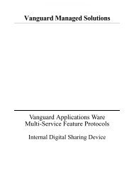
Rear Panel<br />
Figure 2-2 shows the <strong>Vanguard</strong> <strong>3400</strong> <strong>Series</strong> rear panels. The available ports on the<br />
rear panel for the various <strong>3400</strong> models are listed in the table below.<br />
Port 3410 3460 3480<br />
Serial Port 1 Async Yes Yes Yes<br />
Serial Port 1 Sync Yes Yes Yes<br />
CTP Port 4 Yes Yes Yes<br />
Routed Ethernet Port 23 Yes Yes Yes<br />
Routed Ethernet Port 24 Yes Yes ---<br />
Switched Ethernet Port 24 --- --- Yes<br />
Switched Ethernet Port 25 --- --- Yes<br />
Switched Ethernet Port 26 --- --- Yes<br />
Switched Ethernet Port 27 --- --- Yes<br />
Daughtercard Site Port 7 Yes Yes Yes<br />
Daughtercard Site Port 10 --- Yes Yes<br />
2-2 Hardware Description
Enclosure<br />
3410<br />
DC Site 1<br />
Ports 7-9<br />
5V DC<br />
Power<br />
Input<br />
3460<br />
RS-232 Serial<br />
(Sync/Async)<br />
Port 1<br />
CTP<br />
Port 4<br />
DC Site 1<br />
(Ports 7-9, 51-60)<br />
Routed<br />
Ethernet Ports<br />
Ports 23, 24<br />
DC Site 2<br />
(Ports 10-12, 61-70)<br />
5V DC<br />
Power<br />
Input<br />
Multi-Function CTP<br />
Serial Port 4<br />
Port 1<br />
Routed<br />
Ethernet Ports<br />
Ports 23, 24<br />
3480<br />
DC Site 1<br />
(Ports 7-9)<br />
DC Site 2<br />
(Ports 10-12)<br />
5V DC<br />
Power<br />
Input<br />
Figure 2-2. <strong>Vanguard</strong> <strong>3400</strong> <strong>Series</strong> Rear Panels<br />
Note<br />
For information about cabling, refer to the “Cabling Your <strong>Vanguard</strong> <strong>3400</strong><br />
<strong>Series</strong>” section in Chapter 3.<br />
Caution<br />
Multi-Function CTP<br />
Serial Port 4<br />
Port 1<br />
Routed<br />
Ethernet Port<br />
Port 23<br />
Switched/Routed<br />
Ethernet Ports<br />
Ports 24, 25, 26, 27<br />
Do not connect Ports 4, 23, 24 25, 26, or 27 to the Public Communications Network.<br />
Serial Numbers<br />
The Hardware Serial Number indicates the version of hardware in your unit. The<br />
serial number label is located on the rear panel of the <strong>Vanguard</strong> <strong>3400</strong> <strong>Series</strong>.<br />
Refer to the serial number when contacting your <strong>Vanguard</strong> <strong>Networks</strong> Service<br />
Representatives.<br />
Hardware Description 2-3
Enclosure<br />
Serial Number Label<br />
Figure 2-3. <strong>Vanguard</strong> <strong>3400</strong> <strong>Series</strong> Serial Number Label Location<br />
2-4 Hardware Description
Motherboard<br />
Motherboard<br />
General<br />
Description<br />
The <strong>Vanguard</strong> <strong>3400</strong> <strong>Series</strong> motherboard contains 16 MB flash and 64 MB of<br />
SDRAM memory. It uses the MPC8270 CPU operated in single MPC 8270 mode.<br />
Additionally, the motherboard supports the following:<br />
• One or two daughtercards, depending on which model you have (see daughtercard<br />
matrix on page 2-9 for model-specific support)<br />
• One Serial Port. Depending on which model you have this is either a Multi-<br />
Protocol interface (UDIMM or software configurable for V.11/X.21, V.24/<br />
RS232, V.35, or V.36) or a RS232 only interface configured as DCE.<br />
• Up to two 10/100 Base T auto-sensing Ethernet ports. (Refer to rear panel<br />
matrix on page 2-2 for support by model)<br />
• One CTP port<br />
• One 4-port Ethernet Switch (refer to rear panel matrix on page 2-2 for support<br />
by model)<br />
• Two Front Panel green LEDS; Power and Status<br />
• Connector for external 5V power supply<br />
• Encryption PCI Mezzanine card<br />
• Real Time Clock Battery<br />
• Cooling Fan (3460/3480 only)<br />
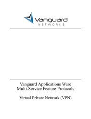
Refer to Figure 2-4, Figure 2-5, and Figure 2-6 for the location of the motherboard<br />
components for the 3410, 3460, and 3480 respectively.<br />
Hardware Description 2-5
Motherboard<br />
Future Expansion Connection for Upgradeablity<br />
Daughtercard Slot 1<br />
Serial Number Label<br />
Encryption Module<br />
Battery<br />
Figure 2-4. <strong>Vanguard</strong> 3410 <strong>Series</strong> Motherboard<br />
2-6 Hardware Description
Motherboard<br />
Future Expansion Connection for Upgradeablity<br />
Daughtercard Slot 1<br />
Serial Number Label<br />
Encryption Module<br />
Daughtercard Slot 2<br />
Fan<br />
Battery<br />
Figure 2-5. <strong>Vanguard</strong> 3460 <strong>Series</strong> Motherboard<br />
Hardware Description 2-7
Motherboard<br />
Future Expansion Connection for Upgradeablity<br />
Daughtercard Slot 1 Serial Number Label<br />
Encryption Module<br />
Daughtercard Slot 2<br />
Fan<br />
Battery<br />
Figure 2-6. <strong>Vanguard</strong> 3480 <strong>Series</strong> Motherboard<br />
Accessing the<br />
Motherboard<br />
To access the motherboard components you must remove the motherboard from the<br />
enclosure.<br />
• For information about removing and installing the motherboard refer to the<br />
“Accessing the Motherboard” section in Chapter 3.<br />
• For information about removing or installing motherboard components, refer<br />
to the “Modifying Your <strong>Vanguard</strong> <strong>3400</strong> <strong>Series</strong>” section in Chapter 3.<br />
2-8 Hardware Description
<strong>Vanguard</strong> <strong>Networks</strong> Daughtercards<br />
<strong>Vanguard</strong> <strong>Networks</strong> Daughtercards<br />
Supported<br />
Daughtercards<br />
The table below identifies the daughtercards supported by each <strong>3400</strong> series model, as<br />
well as any daughtercard slot restrictions that may apply.<br />
Description<br />
<strong>Vanguard</strong> 3410/3460/3480 Daughtercard Matrix<br />
Product Assembly 3410 3460 3480<br />
Code Number<br />
DC<br />
Site<br />
DC<br />
Site 1<br />
DC<br />
Site 2<br />
DC<br />
Site 1<br />
DC<br />
Site 2<br />
2P-SDC (2-Port Serial) 1130-10004 --- Yes --- Yes ---<br />
56K CSU 68472 Yes Yes Yes Yes Yes<br />
Dual E&M 65729 --- Yes Yes Yes Yes<br />
Dual FXS 68372 --- Yes Yes Yes Yes<br />
FT1 - 120 Ohm 1600-00001 Yes Yes Yes Yes Yes<br />
FE1 - 75 Ohm 1600-00075 Yes Yes Yes Yes Yes<br />
FE1 - 120 Ohm 1600-00120 Yes Yes Yes Yes Yes<br />
FXS/FXO 80019 --- --- --- --- ---<br />
G.SHDSL 1152-10009 --- --- --- --- ---<br />
Quad FXO 1152-10035 --- Yes Yes Yes Yes<br />
Quad FXS 1152-10034 --- Yes Yes Yes Yes<br />
ISDN BRI S/T 68525 --- --- --- --- ---<br />
ISDN BRI S/T 1152-10005 --- Yes Yes Yes Yes<br />
ISDN BRI-U 68434 --- --- --- --- ---<br />
V.11 DCE (Serial) 49649 --- Yes Yes Yes Yes<br />
V.24 DCE (Serial) 49646 --- Yes Yes Yes Yes<br />
V.35 DCE (Serial) 49647 --- Yes Yes Yes Yes<br />
V.36 DCE (Serial) 49648 --- Yes Yes Yes Yes<br />
V.11 DTE (Serial) 49661 --- Yes Yes Yes Yes<br />
V.24 DTE (Serial) 49658 --- Yes Yes Yes Yes<br />
V.35 DTE (Serial) 49659 --- Yes Yes Yes Yes<br />
V.36 DTE (Serial) 49660 --- Yes Yes Yes Yes<br />
V.90 (Modem) 1152-10003 --- Yes Yes Yes Yes<br />
BRI Voice 68525 Yes Yes Yes Yes<br />
Note<br />
If a table entry contains the value "Yes", the daughtercard type will be supported<br />
in the DC Site for that platform.<br />
If a table entry contains the entry " --- ", the daughtercard type will not be<br />
supported in that DC Site of that platform<br />
Hardware Description 2-9
<strong>Vanguard</strong> <strong>Networks</strong> Daughtercards<br />
Daughtercard<br />
Compatibility<br />
Older <strong>Vanguard</strong> <strong>Networks</strong> Daughtercards do not fit into the <strong>Vanguard</strong> <strong>3400</strong> <strong>Series</strong>.<br />
You can only use the newer daughtercards which are identified by a dimple as shown<br />
in Figure 2-7. If the dimple is not present, do not attempt to use the Daughtercard in<br />
the <strong>Vanguard</strong> <strong>3400</strong> <strong>Series</strong>.<br />
Also, when installing a <strong>Vanguard</strong> <strong>Networks</strong> Daughtercard into a <strong>3400</strong> <strong>Series</strong>, you<br />
must use the shorter two-sided header. The taller header is used with other <strong>Vanguard</strong><br />
<strong>Networks</strong> units.<br />
Dimple<br />
BRI-S/T DATA<br />
TERMINAL<br />
LINE<br />
LINK<br />
D-ACT<br />
Figure 2-7. New <strong>Vanguard</strong> <strong>3400</strong> <strong>Series</strong> Daughtercard Example<br />
Caution<br />
If you attempt to force an older <strong>Vanguard</strong> <strong>Networks</strong> Daughtercard into a <strong>Vanguard</strong><br />
<strong>3400</strong> <strong>Series</strong>, the equipment will be damaged.<br />
If you have an older <strong>Vanguard</strong> <strong>Networks</strong> Daughtercard and would like to use it in a<br />
<strong>Vanguard</strong> <strong>3400</strong> <strong>Series</strong>, contact your service representative about having the card<br />
reworked.<br />
56K DSU/CSU<br />
Daughtercard<br />
The 56K DSU Daughtercard provides an RJ48S connector and can support speeds of<br />
56 kbps (synchronous). It conforms to AT&T 62310 point-to-point and multipoint,<br />
and to ANSI T1/E1.4/91-006 56 kbps. The card supports the following capabilities:<br />
• Internal/external clocking<br />
• Internal/external loopback<br />
• 4-wire line driver operation<br />
The card also supports multidrop DSUs when either of these conditions exist:<br />
• If a MARK Idle protocol is used (such as MX25).<br />
• If the Telco uses an OR'ed or Data Contention is used to mix individual DRU<br />
drops.<br />
Figure 2-8 shows the 56K DSU/CSU Daughtercard connector as it appears on the<br />
back panel.<br />
DSU<br />
Figure 2-8. 56K DSU/CSU Daughtercard Connector<br />
2-10 Hardware Description
<strong>Vanguard</strong> <strong>Networks</strong> Daughtercards<br />
4-Port Voice FXS<br />
Daughtercard<br />
The <strong>Vanguard</strong> Quad FXS Daughter Card is supported on the <strong>Vanguard</strong> 3460/3480.<br />
The 4-Port Voice FXS Daughtercard has four RJ11 connectors for four FXS Ports.<br />
Figure 2-9 shows the 4-Port Voice FXS Daughtercard connectors as they appear on<br />
the back panel.<br />
.<br />
FXS-1 FXS-2 FXS-3 FXS-4<br />
Figure 2-9. FXS Daughtercard<br />
4-Port Voice FXO<br />
Daughtercard<br />
The <strong>Vanguard</strong> Quad FXO Daughter Card is supported on the <strong>Vanguard</strong> 3460/3480.<br />
The 4-Port Voice FXO Daughtercard has four RJ11 connectors for four FXO Ports.<br />
Figure 2-10 shows the 4-Port Voice FXO Daughtercard connectors as they appear on<br />
the back panel.<br />
FXO-1 FXO-2 FXO-3 FXO-4<br />
Figure 2-10. FXO Daughtercard<br />
FT1/FE1<br />
Daughtercards<br />
The FT1/FE1 Daughtercards allow a <strong>Vanguard</strong> 3410/3460/3480 to transfer data over<br />
a T1 or E1 network. The daughtercards support full and fractional, channelized, T1<br />
or E1, and PRI ISDN speeds.<br />
• The FE1 Daughtercard provides line rates 2.048 Mbps and data rates of n x 64<br />
kbps (where n is 1 to 31) per channel.<br />
• The FT1 Daughtercard provides line rates 1.544 Mbps and data rates of n x 64<br />
kbps (where n is 1 to 24) per channel.<br />
Figure 2-11 shows the FT1 and the FE1 Daughtercard connectors as they appear on<br />
the back panels. The FT1 Daughtercard has a single RJ48C connector while the FE1<br />
Daughtercard has two BNC connectors along with one RJ48C connector.<br />
\<br />
T1<br />
NTWK<br />
RX<br />
E1<br />
NTWK<br />
TX<br />
ALARM<br />
ALARM<br />
Figure 2-11. FT1 and FE1 Daughtercard Connectors<br />
Note<br />
The FE1 Daughtercard comes with this label which specifies that the E1<br />
interface complies with the Australian requirements ACA TS 016 - 1997 for<br />
connection to E1 SELV services. Also the E1 interface meets the IEC950<br />
specifications for TNV1.<br />
Hardware Description 2-11
<strong>Vanguard</strong> <strong>Networks</strong> Daughtercards<br />
Dual E&M<br />
Daughtercard<br />
The Dual E&M Daughtercard has two E&M interfaces. The ports use RJ11<br />
connectors.<br />
Figure 2-12 shows the Dual E&M Daughtercard connectors as they appear on the<br />
back panel.<br />
LOC<br />
REM<br />
E&M1<br />
E&M2<br />
Figure 2-12. Dual E&M Daughtercard Connectors<br />
V.90 Modem<br />
Daughtercard<br />
The V.90 modem daughtercard provides Async PPP dial back-up for a customers’<br />
applications or can be used for Async dial connections such as remote CTP access.<br />
The V.90 uses a dual RJ-11 for connection to central offices, PBXs or telephone<br />
systems.<br />
Figure 2-13 shows the rear panel connectors on the V.90 modem daughtercard. For<br />
installation instructions, refer to the <strong>Vanguard</strong> Daughtercard <strong>Installation</strong> Guide<br />
(Part Number T0020).<br />
LINE<br />
PHONE<br />
MR<br />
RI . OH<br />
CD<br />
RXD<br />
Figure 2-13. V.90 Modem Daughtercard Connectors<br />
2-Port Serial Data<br />
Card<br />
The 2-Port serial data card has two Sync/Async Universal Serial DCE ports (V.11/<br />
X.21, V.24/RS232, V.35, or V.36). These ports are independent of each other and<br />
require a Y-cable which provides two DB25 ports. The required Y-cable is supplied<br />
with the card or can be ordered separately.<br />
Note<br />
A cable adapter is required to use current <strong>Vanguard</strong> <strong>Networks</strong> Adapter Cables<br />
when running V.11/X.21, V.35, or V.36. (See “Cable Adapters and Special<br />
Cables” section on page 3-8)<br />
To emulate a DTE port, the special cables listed below are also required.<br />
• For V.11/X.21, use 51176 DCE-DTE cable adapter and 1152-10022 V.11/<br />
X.21 cable adapter<br />
• For V.24/RS232, use 80110 (or equivalent)<br />
• For V.35 or V.36, use 51177 DCE-DTE cable adapter and 1152-10021<br />
V.35/V36 cable adapter<br />
2-12 Hardware Description
<strong>Vanguard</strong> <strong>Networks</strong> Daughtercards<br />
2P-SDC<br />
Figure 2-14. 2-Port Serial Daughtercard Connector<br />
DIM Daughtercard<br />
This card supports a single V.11/X.21, V.24/RS232, V.35, or V.36 DIM (Digital<br />
Interface Module) and can be set as either a DTE or DCE.<br />
Figure 2-15 shows the DIM Daughtercard connector as it appears on the back panel.<br />
DIM SITE<br />
Figure 2-15. DIM Daughtercard Connector<br />
ISDN BRI-U<br />
Daughtercard<br />
This card provides 2B+D Channel through an ISDN BRI U interface. It conforms to<br />
ANSI T1.601 1992 (2B1Q), is LAPD:ITU Q.921 compliant, and supports the<br />
following:<br />
• Integral X.31<br />
• Q.931 dial support<br />
• NI1, 5ESS, DMS-100 switch types<br />
• D Channel Packet Mode<br />
• Leased Circuit Services (I Interface)<br />
• Japan High-Speed Digital<br />
Figure 2-16 shows the ISDN BRI-U Daughtercard connector as it appears on the<br />
back panel.<br />
BRI U<br />
Figure 2-16. ISDN BRI-U Daughtercard Connector<br />
ISDN BRI Voice<br />
Daughtercard<br />
This card provides 2B+D Channel through a BRI S/T interface. It conforms to ITU<br />
I.430, is LAPD:ITU Q.921 compliant, and supports:<br />
• Integral X.31<br />
• ITU-T Q.931 (EURO IDSN) - ETSI switch type to connect to PBXs and<br />
public networks.<br />
• ECMA 143 - QSIG Basic Service to connect to PBXs over private line.<br />
• ECMA 165 - QSIG Generic Functions for Support of PBX Supplementary<br />
Hardware Description 2-13
<strong>Vanguard</strong> <strong>Networks</strong> Daughtercards<br />
Services.<br />
• ITU-T G.711A (A-law) and G.711U (μ-law) interface voice encoding.<br />
• ITU-T G.723, G729, and <strong>Vanguard</strong> <strong>Networks</strong> proprietary CVSELP packet<br />
voice compression.<br />
Figure 2-17 shows the ISDN BRI Voice Daughtercard connectors as they appear on<br />
the back panel.<br />
BRI S<br />
HI Z<br />
S-BUS<br />
S-BUS<br />
100Ω<br />
Figure 2-17. ISDN BRI Voice Daughtercard Connectors<br />
2-Port Voice FXS<br />
Daughtercard<br />
The 2-Port Voice FXS Daughtercard has two RJ11 connectors for two FXS Ports.<br />
The two ports can be used simultaneously and each port supports one voice channel.<br />
Figure 2-18 shows the 2 Port Voice FXS Daughtercard connectors as they appear on<br />
the back panel.<br />
LOC<br />
1 2<br />
FXS-1<br />
FXS-2<br />
REM<br />
Figure 2-18. 2-Port Voice FXS Daughtercard Connectors<br />
Note<br />
Calls between two FXS ports within the same <strong>Vanguard</strong> 6460/3480 are not<br />
supported.<br />
Enhanced ISDN<br />
BRI-S/T<br />
Daughtercard<br />
This card provides 2B+D Channel through a BRI S/T interface. It conforms to ITU<br />
I.430, is LAPD:ITU Q.921 compliant, and supports:<br />
• Integral X.31<br />
• Q.931 dial support<br />
• NI1, 5ESS, DMS-100, ETSI, Euro Numeris switch types<br />
• D Channel Packet Mode<br />
• Leased Circuit Services (I Interface)<br />
• Permanent B for German Monopol support or Japan High-Speed Digital<br />
Figure 2-19 shows the ISDN BRI-S/T Daughtercard connectors as they appear on<br />
the back panel.<br />
BRI-S/T DATA<br />
TERMINAL<br />
LINE<br />
LINK<br />
D-ACT<br />
Figure 2-19. Enhanced BRI-S/T Daughtercard Connectors<br />
2-14 Hardware Description
<strong>Vanguard</strong> <strong>Networks</strong> Daughtercards<br />
Modules<br />
The <strong>Vanguard</strong> <strong>3400</strong> <strong>Series</strong> can support an optional Encryption Module. The<br />
<strong>Vanguard</strong> <strong>3400</strong> <strong>Series</strong> Encryption Module provides DES/3DES/AES hardware<br />
accelerated encryption. For information on installing or removing this module, refer<br />
to the “Installing and Removing the Encryption PCI Mezzanine Card” section in<br />
Chapter 3.<br />
Hardware Description 2-15
<strong>Vanguard</strong> <strong>Networks</strong> Daughtercards<br />
2-16 Hardware Description
Chapter 3<br />
<strong>Installation</strong> and Replacement<br />
Overview<br />
Introduction<br />
This chapter provides instructions for the following tasks:<br />
• Checking Your Shipment Contents.<br />
• Installing the <strong>Vanguard</strong> <strong>3400</strong> <strong>Series</strong>.<br />
• Cabling the <strong>Vanguard</strong> <strong>3400</strong> <strong>Series</strong>.<br />
• Modifying Your <strong>Vanguard</strong> <strong>3400</strong> <strong>Series</strong>.<br />
<strong>Installation</strong> and Replacement 3-1
Checking Your Shipment Contents<br />
Checking Your Shipment Contents<br />
List of Contents<br />
Before you install the <strong>Vanguard</strong> <strong>3400</strong> <strong>Series</strong>, make sure your shipment contents are<br />
complete.<br />
The <strong>Vanguard</strong> <strong>3400</strong> <strong>Series</strong> is packaged in shock-absorbent packing material. Inside<br />
your shipping carton, you should find the contents shown in Figure 3-1.<br />
<strong>Vanguard</strong> <strong>3400</strong> <strong>Series</strong><br />
<strong>Vanguard</strong> <strong>3400</strong> <strong>Series</strong> Power Supply<br />
<strong>Vanguard</strong> <strong>3400</strong> <strong>Series</strong> Shipping Contents<br />
• <strong>Vanguard</strong> <strong>3400</strong> <strong>Series</strong> enclosure<br />
• Power Supply<br />
Line Cord<br />
(Optional)<br />
Figure 3-1. <strong>Vanguard</strong> <strong>3400</strong> <strong>Series</strong> Shipping Contents<br />
3-2 <strong>Installation</strong> and Replacement
Installing The <strong>Vanguard</strong> <strong>3400</strong> <strong>Series</strong><br />
Installing The <strong>Vanguard</strong> <strong>3400</strong> <strong>Series</strong><br />
Introduction<br />
This section explains how to install the <strong>Vanguard</strong> <strong>3400</strong> <strong>Series</strong>. It consists of these<br />
sections:<br />
• Selecting and preparing the installation site.<br />
• <strong>Installation</strong>.<br />
• Thermal considerations.<br />
• Cabling.<br />
After the <strong>Vanguard</strong> <strong>3400</strong> <strong>Series</strong> is installed and cabled, go to Chapter 4, Powering<br />
Up Your <strong>Vanguard</strong> <strong>3400</strong> <strong>Series</strong> for instructions for powering-up the unit.<br />
<strong>Installation</strong> and Replacement 3-3
Installing The <strong>Vanguard</strong> <strong>3400</strong> <strong>Series</strong><br />
<strong>Installation</strong><br />
How to Choose a<br />
Site<br />
Before you install the <strong>Vanguard</strong> <strong>3400</strong> <strong>Series</strong>, select a site for the device.<br />
Choose a site that is within an appropriate distance of a power source. Depending on<br />
your application, and the country in which the <strong>Vanguard</strong> <strong>3400</strong> <strong>Series</strong> is to operate,<br />
the power source must be a grounded 110 to 220 Vac outlet.<br />
Leave at least 2 inches (5 cm) of clearance in front of the front panel, to allow you to<br />
see the front panel LEDs, and 6-inches behind the unit for cable clearances (see<br />
Figure 3-2). For proper ventilation, leave 2 inches (5 cm) of clearance on the sides.<br />
The site should be free of accumulated dust and environmental extremes. Refer to<br />
Appendix A, Specifications for details.<br />
Minimum 2-inches (5 cm) Front<br />
and 6-inches (15 cm) Rear<br />
Note: Do not remove the rubber<br />
feet from the bottom of the<br />
unit. They allow for proper<br />
air flow.<br />
Minimum 2-inches (5 cm)<br />
on either side for ventilation.<br />
Figure 3-2. Proper Cable and Air Clearance<br />
Caution<br />
<strong>Vanguard</strong> <strong>3400</strong> <strong>Series</strong> devices should be used in environments designed for<br />
computers and electronic equipment. In areas susceptible to lightning, take<br />
precautions to prevent damage to electronic equipment. Contact your telephone<br />
company or an electronic accessories vendor for information on lightning protection<br />
equipment. Customers experiencing problems caused by surges from lightning have<br />
eliminated such problems by installing appropriate surge suppressors on power and<br />
data lines.<br />
3-4 <strong>Installation</strong> and Replacement
Installing The <strong>Vanguard</strong> <strong>3400</strong> <strong>Series</strong><br />
<strong>Installation</strong><br />
Complete these steps to install the unit:<br />
Step<br />
Action<br />
1 Unpack the <strong>Vanguard</strong> <strong>3400</strong> <strong>Series</strong>, and inspect the unit to ensure you have<br />
all the components.<br />
2 Install any daughtercards that you need to add to the unit, as necessary.<br />
3 Be sure that the four rubber feet are on the bottom of the enclosure.<br />
4 Attach the power cord and cables to the rear panel. Refer to the “Cabling<br />
Your <strong>Vanguard</strong> <strong>3400</strong> <strong>Series</strong>” section on page 3-7 for cabling information.<br />
Note<br />
Cable Adapters are required when installing the <strong>Vanguard</strong> <strong>3400</strong> <strong>Series</strong> into<br />
an existing site that already has <strong>Vanguard</strong> <strong>Networks</strong> high-speed (V.11/<br />
X.21, V.35, or V.36) Adapter Cables. (See “Cable Adapters and Special<br />
Cables” section on page 3-8)<br />
5 Place the enclosure in the selected site, and power unit on. Do not block<br />
the chassis vents.<br />
6 Ensure that the ambient temperature is within the temperature range specified<br />
in Appendix A.<br />
Note<br />
You can stack as many as three <strong>Vanguard</strong> <strong>3400</strong> <strong>Series</strong> units on top of each other.<br />
Caution<br />
Do not place items weighing more than 20 pounds (9 kg) on top of a <strong>Vanguard</strong><br />
<strong>3400</strong> <strong>Series</strong> enclosure.<br />
<strong>Installation</strong> and Replacement 3-5
Installing The <strong>Vanguard</strong> <strong>3400</strong> <strong>Series</strong><br />
Thermal Considerations<br />
Introduction<br />
Temperature<br />
This section explains some of the heat and temperature factors that can affect your<br />
<strong>Vanguard</strong> <strong>3400</strong> <strong>Series</strong>.<br />
After the unit is running, check the ambient air temperature. Make sure it does not<br />
exceed the operating temperature limits specified in Appendix A.<br />
Other conditions that could impact internal temperature of the <strong>Vanguard</strong> <strong>3400</strong> <strong>Series</strong><br />
include:<br />
• Blocked vents<br />
• Insufficient clearance around the unit<br />
• Fan (if this unit is provided with one) is not working properly<br />
• Rubber feet (4) not installed on bottom of chassis<br />
3-6 <strong>Installation</strong> and Replacement
Installing The <strong>Vanguard</strong> <strong>3400</strong> <strong>Series</strong><br />
Cabling Your <strong>Vanguard</strong> <strong>3400</strong> <strong>Series</strong><br />
Introduction<br />
This section provides information to help you cable your <strong>Vanguard</strong> <strong>3400</strong> <strong>Series</strong>.<br />
Caution<br />
Before connecting cables to the motherboard or daughtercard ports, be sure that the<br />
screws holding the motherboard in place are installed. Otherwise, the motherboard<br />
could loosen under the weight of the cables and cause damage to the equipment.<br />
Also use proper cable strain relief to prevent damage due to excessive cable weight.<br />
Rear Panel Port<br />
Numbering<br />
Figure 3-3 shows the port numbering on the <strong>Vanguard</strong> <strong>3400</strong> <strong>Series</strong> rear panels.<br />
3410<br />
DC Site 1<br />
Ports 7-9<br />
5V DC<br />
Power<br />
Input<br />
3460<br />
RS-232 Serial<br />
(Sync/Async)<br />
Port 1<br />
CTP<br />
Port 4<br />
DC Site 1<br />
(Ports 7-9, 51-60)<br />
Routed<br />
Ethernet Ports<br />
Ports 23, 24<br />
DC Site 2<br />
(Ports 10-12, 61-70)<br />
5V DC<br />
Power<br />
Input<br />
Multi-Function CTP<br />
Serial Port 4<br />
Port 1<br />
Routed<br />
Ethernet Ports<br />
Ports 23, 24<br />
3480<br />
DC Site 1<br />
(Ports 7-9)<br />
DC Site 2<br />
(Ports 10-12)<br />
5V DC<br />
Power<br />
Input<br />
Multi-Function CTP<br />
Serial Port 4<br />
Port 1<br />
Routed<br />
Ethernet Port<br />
Port 23<br />
Switched/Routed<br />
Ethernet Ports<br />
Ports 24, 25, 26, 27<br />
Figure 3-3. <strong>Vanguard</strong> <strong>3400</strong> <strong>Series</strong> Rear Panel Port Numbers<br />
<strong>Installation</strong> and Replacement 3-7
Installing The <strong>Vanguard</strong> <strong>3400</strong> <strong>Series</strong><br />
Caution<br />
Do not connect the Ports 4, 23, 24, 25, 26, or 27 to the Public Communications<br />
Network.<br />
Note<br />
When installing a daughtercard with only one port, the port number is 7 or 10<br />
(depending on the location of the card).<br />
Rear Panel Ports<br />
There are up to seven physical ports on the <strong>Vanguard</strong> <strong>3400</strong> <strong>Series</strong> rear panel. Some<br />
physical port numbers may vary from model to model.<br />
Port 1<br />
Port 1 is either a Universal Serial Port (DB25 connector) which can be configured to<br />
support V.11/X.21, V.24/RS232, V.35 and V.36 DCE, or an RS232 only interface.<br />
Note<br />
Cable Adapters are required when using V.11/X.21, V.35, or V.36.<br />
Cable Adapters and Special Cables<br />
To emulate a high speed DTE interface V.11/X.21, V.35, or V.36 on any <strong>3400</strong> <strong>Series</strong><br />
Universal Serial Port requires the use of a Cable Adapter (Figure 3-4) and special<br />
cables.<br />
1152-10022<br />
REV. 1<br />
V.11<br />
X.21<br />
1152-10021<br />
REV. 1<br />
V.35<br />
V.36<br />
Figure 3-4. Cable Adapters<br />
The table below provides a description with part numbers of the Cable Adapter and<br />
special cables. The paragraphs that follow provide more detailed information and<br />
pinouts.<br />
3-8 <strong>Installation</strong> and Replacement
Installing The <strong>Vanguard</strong> <strong>3400</strong> <strong>Series</strong><br />
Cabling<br />
Interface Type<br />
.<br />
<strong>3400</strong> <strong>Series</strong> Motherboard Port 1 and 2-Port Serial Data Card Interface<br />
Y-Cable<br />
(one per<br />
2-PSDC)<br />
Cable Adapter<br />
(one per port)<br />
DCE-DTE crossover<br />
Cable (one per port)<br />
Adapter Cable<br />
(one per port)<br />
Motherboard Port 1<br />
V.24/RS232 DCE N/A N/A N/A 80113<br />
15' DB25M-DB25F<br />
V.24/RS232 DTE N/A N/A 80110<br />
3' DB25M-DB25M<br />
or 80109<br />
15' DB25M-DB25M<br />
N/A<br />
V.35 or V.36 DCE N/A 1152-10021<br />
DB25M-DB25F<br />
V.35 or V.36 DTE N/A 1152-10021<br />
DB25M-DB25F<br />
V.11/X.21 DCE N/A 1152-10022<br />
DB25M-DB25F<br />
V.11/X.21 DTE N/A 1152-10022<br />
DB25M-DB25F<br />
2-Port Serial Data Card<br />
V.24/RS232 DCE<br />
V.24/RS232 DTE<br />
62026-01 DB50Mtwo<br />
DB25Fs<br />
62026-01 DB50Mtwo<br />
DB25Fs<br />
V.35 or V.36 DCE 62026-01<br />
DB50M-two<br />
DB25Fs<br />
V.35 or V.36 DTE 62026-01<br />
DB50M-two<br />
DB25Fs<br />
V.11/X.21 DCE 62026-01<br />
DB50M-two<br />
DB25Fs<br />
V.11/X.21 DTE 62026-01<br />
DB50M-two<br />
DB25Fs<br />
N/A 92104<br />
7' DB25M-M34F<br />
51177<br />
1' DB25M-DB25F<br />
91917<br />
7' DB25M-M34M<br />
N/A 92089<br />
7' DB25M-DB15F<br />
51176<br />
1' DB25M-DB25F<br />
91918<br />
7' DB25M-DB15M<br />
N/A N/A 80113<br />
15' DB25M-DB25F<br />
N/A 80110<br />
N/A<br />
3' DB25M-DB25M<br />
or 80109<br />
15' DB25M-DB25M<br />
1152-10021<br />
DB25M-DB25F<br />
1152-10021<br />
DB25M-DB25F<br />
1152-10022<br />
DB25M-DB25F<br />
1152-10022<br />
DB25M-DB25F<br />
N/A 92104<br />
7' DB25M-M34F<br />
51177<br />
1' DB25M-DB25F<br />
91917<br />
7' DB25M-M34M<br />
N/A 92089<br />
7' DB25M-DB15F<br />
51176<br />
1' DB25M-DB25F<br />
91918<br />
7' DB25M-DB15M<br />
<strong>Vanguard</strong> <strong>3400</strong><br />
<strong>Series</strong> V.11/X.21<br />
Cable Adapter<br />
Listed below is the pinout of the Cable Adapter that enables the use of existing V.11/<br />
X.21 serial cables on Port 1of the <strong>3400</strong> <strong>Series</strong> platform. The part number is 1152-<br />
10022<br />
<strong>Installation</strong> and Replacement 3-9
Installing The <strong>Vanguard</strong> <strong>3400</strong> <strong>Series</strong><br />
Note<br />
This adapter is also intended to be used in conjunction with the Y-Cable for the<br />
2-Port Serial Data Card.<br />
V.11/X.21 Cable Adapter Pinout<br />
P1 P2<br />
1 1<br />
2 2<br />
3 3<br />
4 4<br />
5 5<br />
6 NC<br />
7 7<br />
8 8<br />
9 9<br />
10 20<br />
11 6<br />
12 22<br />
13 13<br />
14 NC<br />
15 15<br />
16 16<br />
17 17<br />
18 18<br />
19 14<br />
20 NC<br />
21 21<br />
22 NC<br />
23 23<br />
24 24<br />
25 25<br />
<strong>Vanguard</strong> <strong>3400</strong><br />
<strong>Series</strong> V.35/V.36<br />
Cable Adapter<br />
Listed below is the pinout of the Cable Adapter that enables the use of existing V.35<br />
and V.36 serial cables on port 1 of the <strong>3400</strong> <strong>Series</strong> platform. The part number is<br />
1152-10021<br />
Note<br />
This adapter is also intended to be used in conjunction with the Y-Cable for the<br />
2-Port Serial Data Card.<br />
V.35/V.36 Cable Adapter Pinout<br />
P1 P2<br />
1 1<br />
2 2<br />
3-10 <strong>Installation</strong> and Replacement
Installing The <strong>Vanguard</strong> <strong>3400</strong> <strong>Series</strong><br />
V.35/V.36 Cable Adapter Pinout (continued)<br />
P1 P2<br />
3 3<br />
4 4<br />
5 5<br />
6 6<br />
7 7<br />
8 8<br />
9 18<br />
10 10<br />
11 11<br />
12 22<br />
13 13<br />
14 NC<br />
15 15<br />
16 16<br />
17 17<br />
18 NC<br />
19 14<br />
20 20<br />
21 21<br />
22 NC<br />
23 23<br />
24 24<br />
25 25<br />
Special Cables<br />
The special cables required to emulate a high speed DTE interface V.11/X.21, V.35,<br />
or V.36 on any <strong>3400</strong> <strong>Series</strong> Universal Serial Port are listed in the table below for port<br />
1 as well as any 2-Port Serial Data Card:<br />
<strong>Vanguard</strong> <strong>3400</strong> <strong>Series</strong> Special Cables<br />
Part Number<br />
Description<br />
51176 1’ V.11/X.21 DCE–DTE Adapter Cable<br />
51177 1’ V.35 or V.36 DCE–DTE Adapter Cable<br />
<strong>Installation</strong> and Replacement 3-11
Installing The <strong>Vanguard</strong> <strong>3400</strong> <strong>Series</strong><br />
<strong>Vanguard</strong> <strong>3400</strong> <strong>Series</strong> Adapter Cables<br />
Part Number<br />
Modified from<br />
Product Code<br />
Description<br />
80113 15’ DB25M–DB25F Straight Cable, V.24/RS232<br />
92089 7’ DB25M–DB15F Custom Cable, V.11/X.21<br />
91918 7’ DB25M–DB15M Custom Cable, V.11/X.21<br />
92104 7’ DB25M–V.35F Custom Cable, V.35 or V.36<br />
91917 7’ DB25M–M34M Custom Cable, V.35 or V.36<br />
These tables describe the DB25 connector pinouts for port 1 and any 2-Port Serial<br />
Data Card ports:<br />
DB25 V.24 Pinouts (DCE)<br />
Pin ITU Circuit I/O Signal Name<br />
1 --- ----- Protective Ground<br />
2 103 INPUT Transmitted data<br />
3 104 OUTPUT Received data<br />
4 105 INPUT Request To Send<br />
5 106 OUTPUT Clear To Send<br />
6 107 OUTPUT Data Set Ready<br />
7 102 ----- Signal Ground<br />
8 109 OUTPUT Data Carrier Detect<br />
14 --- INPUT Data Restraint Out<br />
15 114 OUTPUT Transmitted Clock<br />
16 --- ----- N/C<br />
17 115 OUTPUT Received Clock<br />
18 --- INPUT External Rx Clock<br />
20 108/2 INPUT Data Terminal Ready<br />
21 --- ----- N/C<br />
22 125 OUTPUT Ring Indicator<br />
24 113 INPUT External Tx Clock<br />
25 142 INPUT Make Busy<br />
3-12 <strong>Installation</strong> and Replacement
Installing The <strong>Vanguard</strong> <strong>3400</strong> <strong>Series</strong><br />
DB25 V.35/V.36 Pinouts<br />
Note<br />
For port 1 and any 2-Port Serial Data Card after<br />
the 1152-10021 Cable Adapter is installed.<br />
Pin Signal DCE Position<br />
1 GND -------<br />
2 TXD A IN<br />
3 RXD A OUT<br />
4 RTS IN<br />
5 CTS OUT<br />
6 DSR OUT<br />
7 SIG GND -------<br />
8 DCD OUT<br />
14 TXD B IN<br />
15 TXC A OUT<br />
16 RXD B OUT<br />
17 RXC A OUT<br />
18 RXC B OUT<br />
20 DTR IN<br />
21 TXC B OUT<br />
22 ETXC B IN<br />
24 ETXC A IN<br />
25 (V.36 only) TM NC<br />
DB25 V.11/X.21 Pinouts<br />
Note<br />
For port 1 and any 2-Port Serial Data Card after<br />
the 1152-10022 Cable Adapter is installed.<br />
Pin Signal DCE Position<br />
1 GND -------<br />
2 TXD A IN<br />
3 RXD A OUT<br />
4 RTS A IN<br />
6 DCD B OUT<br />
7 SIG GND -------<br />
8 DCD A OUT<br />
14 TXD B IN<br />
15 TXC A OUT<br />
<strong>Installation</strong> and Replacement 3-13
Installing The <strong>Vanguard</strong> <strong>3400</strong> <strong>Series</strong><br />
DB25 V.11/X.21 Pinouts (continued)<br />
Note<br />
For port 1 and any 2-Port Serial Data Card after<br />
the 1152-10022 Cable Adapter is installed.<br />
Pin Signal DCE Position<br />
16 RXD B OUT<br />
20 RTS B IN<br />
21 TXC B OUT<br />
22 ETXC B IN<br />
24 ETXC A IN<br />
Port 4<br />
This port has an RJ-45 connector. Use Port 4 as the CTP for communicating with,<br />
configuring, monitoring, and for coldloading the node. Figure 3-5 shows the pin<br />
numbers for port 4.<br />
Pin 1<br />
Pin 8<br />
Figure 3-5. Port 4 Pin Numbers<br />
This table shows the pinouts for RJ-45 connectors for port 4:<br />
Pin Number<br />
Port 4 (CTP)<br />
Signal<br />
DCE<br />
1 RTS Input<br />
2 DTR Input<br />
3 RXD Output<br />
4 DCD Output<br />
5 GND -------<br />
6 TXD Input<br />
7 DSR Output<br />
8 CTS Output<br />
Note<br />
Use Port 4 only with low speed asynchronous protocols. Running asynchronous<br />
protocols at speeds greater than 19.2 kbps may degrade node performance.<br />
3-14 <strong>Installation</strong> and Replacement
Installing The <strong>Vanguard</strong> <strong>3400</strong> <strong>Series</strong><br />
Port 23 and Port 24 This table shows the pinouts for the RJ45 Ethernet connector for Port 23 and Port 24<br />
when functioning as a routed Ethernet port.<br />
Pin<br />
1 Transmit Positive<br />
2 Transmit Negative<br />
3 Receive Data Positive<br />
4 Not Used<br />
5 Not Used<br />
6 Receive Data Negative<br />
7 Not Used<br />
8 Not Used<br />
Signal<br />
Ports 24, 25, 26 and<br />
27<br />
This table shows the pinouts for the RJ45 connector for Switched Ethernet Ports 24<br />
(when functioning as a switched Ethernet port), 25, 26, 27<br />
Pin<br />
1 Receive Data Positive<br />
2 Receive Data Negative<br />
3 Transmit Data Positive<br />
4 Not Used<br />
5 Not Used<br />
6 Transmit Data Negative<br />
7 Not Used<br />
8 Not Used<br />
Signal<br />
Cabling Daughtercards<br />
For instructions on cabling your standard <strong>Vanguard</strong> Daughtercards, refer to the<br />
<strong>Vanguard</strong> Daughtercard <strong>Installation</strong> Guide (Part Number T0020).<br />
Cabling 2-Port<br />
Serial Card<br />
The 2-Port Serial Card comes with one Y-Cable Adapter as shown in Figure 3-6.<br />
They allow the connector on the rear of the 2-Port Serial Card to support two ports.<br />
Note<br />
The Cable Adapter (Figure 3-4) is required on all Universal Serial Ports<br />
(motherboard and 2-Port Serial Data Card) to use existing <strong>Vanguard</strong> <strong>Networks</strong><br />
Adapter Cables when running high-speed V.11/X.21, V.35, or V.36.<br />
<strong>Installation</strong> and Replacement 3-15
Installing The <strong>Vanguard</strong> <strong>3400</strong> <strong>Series</strong><br />
Figure 3-6. 2-Port Serial Card Y-Cable (P/N 62026-01)<br />
3-16 <strong>Installation</strong> and Replacement
Modifying Your <strong>Vanguard</strong> <strong>3400</strong> <strong>Series</strong><br />
Modifying Your <strong>Vanguard</strong> <strong>3400</strong> <strong>Series</strong><br />
Introduction<br />
You can modify your <strong>Vanguard</strong> <strong>3400</strong> <strong>Series</strong> by adding or replacing daughtercards or<br />
mini-PCI modules. This section explains how to make these modifications.<br />
Daughtercards You can install up to two <strong>Vanguard</strong> <strong>Networks</strong> Daughtercards in the <strong>Vanguard</strong> <strong>3400</strong><br />
<strong>Series</strong>.<br />
• For information about installing a standard <strong>Vanguard</strong> Daughtercard, refer to<br />
the sample daughtercard installation illustration in Figure 3-7 or the <strong>Vanguard</strong><br />
Daughtercard <strong>Installation</strong> Guide (Part Number T0020).<br />
When installing a <strong>Vanguard</strong> Daughtercard into a <strong>3400</strong> <strong>Series</strong>, you must use the<br />
shorter two-sided header. The taller header is used with other <strong>Vanguard</strong> units.<br />
Remove a Daughtercard<br />
1 Locate the Daughtercard you want to remove<br />
and loosen the screws that are holding it to the<br />
back panel.<br />
2 Loosen and remove the mounting screw(s).<br />
3 Carefully lift out the daughtercard.<br />
Sample Daughtercard<br />
Two-Sided Header<br />
Blank Filler Panel<br />
Install a Daughtercard<br />
1 Locate the slot where you want to install the Daughtercard and remove the filler<br />
panel by loosening the screws.<br />
Note<br />
If original Blank Panel is installed, insert a screwdriver into the slot at the center<br />
(as shown in inset) of the filler panel and work the screwdriver up and down to<br />
loosen the panel. Detach the filler panel from the tabs at each end and remove.<br />
2 Carefully position the Daughtercard over the connector. Press down firmly so the<br />
daughtercard connector seats properly with the motherboard connector.<br />
3<br />
Secure the Daughtercard with the mounting screws on the back panel.<br />
CAUTION: Ensure that daughtercard connector pins are properly aligned with<br />
the corresponding motherboard connector to prevent damage to the card when<br />
power is applied.<br />
Figure 3-7. Sample Daughtercard <strong>Installation</strong><br />
<strong>Installation</strong> and Replacement 3-17
Modifying Your <strong>Vanguard</strong> <strong>3400</strong> <strong>Series</strong><br />
Accessing the Motherboard<br />
Introduction<br />
This section explains how to access the motherboard for the <strong>Vanguard</strong> <strong>3400</strong> <strong>Series</strong>. It<br />
also identifies the location of the key motherboard components.<br />
Before replacing modules, fans, batteries, or daughtercards, you must access the<br />
<strong>Vanguard</strong> <strong>3400</strong> <strong>Series</strong> motherboard.<br />
Instructions for the<br />
<strong>3400</strong> <strong>Series</strong><br />
Figure 3-8 shows how to remove and install the <strong>Vanguard</strong> <strong>3400</strong> <strong>Series</strong> motherboard.<br />
Figure 3-9 shows the location of the components on the motherboard.<br />
Warning<br />
To prevent injury and damage to the equipment, power down the unit and disconnect<br />
the power cord before you remove or install the motherboard.<br />
Avertissement<br />
Pour éviter toute blessure ou endommagement de l’équipement, éteignez l’unité et<br />
déconnectez le cordon d’alimentation avant d’enlever ou d’installer la carte mère.<br />
Warnung<br />
Um persönliche Verletzungen und Schäden am Gerät zu verhindern, schalten Sie das<br />
Gerät ab, und ziehen Sie den Netzstecker aus, bevor Sie die Hauptplatine entfernen<br />
oder installieren.<br />
Caution<br />
Use care when handling and placing the motherboard on a surface. There are<br />
components on the bottom of the motherboard that can be damaged.<br />
Caution<br />
Some components used in the <strong>3400</strong> <strong>Series</strong> are sensitive to static electric discharges;<br />
static electric discharges can cause damage to internal components. Use proper<br />
handling and grounding precautions whenever handling cards and components.<br />
Mise en Garde<br />
Certains composants du <strong>3400</strong> <strong>Series</strong> sont sensibles aux décharges électrostatiques<br />
qui peuvent les endommager. Prenez les dispositions et précautions de mise à la terre<br />
nécessaires lors de la manipulation de cartes et de composants.<br />
Vorsicht<br />
Einige im <strong>3400</strong> <strong>Series</strong> verwendeten Komponenten sollten keinen elektrostatischen<br />
Entladungen ausgesetzt werden, durch die interne Bauteile beschädigt werden<br />
können. Wenden Sie die entsprechenden Maßnahmen zur Erdung und zum Schutz<br />
vor statischen Ladungen bei der Handhabung von Karten und Komponenten an.<br />
3-18 <strong>Installation</strong> and Replacement
Modifying Your <strong>Vanguard</strong> <strong>3400</strong> <strong>Series</strong><br />
Caution<br />
When handling any components or cards, use ESD protection.<br />
Removing the Motherboard<br />
1<br />
2<br />
3<br />
4<br />
Power down the unit and remove the cables<br />
and power cord.<br />
Remove the two screws on either side of the<br />
motherboard rear panel.<br />
Pull motherboard out of chassis by grabbing<br />
the bottom edge of rear panel and carefully<br />
sliding it out of chassis.<br />
Place the motherboard on a clean flat surface.<br />
Installing the Motherboard<br />
1<br />
2<br />
3<br />
Carefully slide the motherboard into the card guides within the<br />
chassis opening, then push the motherboard into the enclosure.<br />
Install and tighten screws on both sides of the rear panel. Be sure<br />
the screws are snug.<br />
Reconnect the cables and power cord and power up the unit.<br />
Figure 3-8. <strong>Vanguard</strong> <strong>3400</strong> <strong>Series</strong> Motherboard Removal and<br />
Replacement<br />
<strong>Installation</strong> and Replacement 3-19
Modifying Your <strong>Vanguard</strong> <strong>3400</strong> <strong>Series</strong><br />
Motherboard<br />
Components<br />
Figure 3-9, Figure 3-10, and Figure 3-11 show the components on a <strong>Vanguard</strong> <strong>3400</strong><br />
<strong>Series</strong> motherboard.<br />
Future Expansion Connection for Upgradeablity<br />
Daughtercard Slot 1<br />
Serial Number Label<br />
Encryption Module<br />
Battery<br />
Figure 3-9. Location of the 3410 Motherboard Components<br />
3-20 <strong>Installation</strong> and Replacement
Modifying Your <strong>Vanguard</strong> <strong>3400</strong> <strong>Series</strong><br />
Future Expansion Connection for Upgradeablity<br />
Daughtercard Slot 1<br />
Serial Number Label<br />
Encryption Module<br />
Daughtercard Slot 2<br />
Fan<br />
Battery<br />
Figure 3-10. Location of the 3460 Motherboard Components<br />
<strong>Installation</strong> and Replacement 3-21
Modifying Your <strong>Vanguard</strong> <strong>3400</strong> <strong>Series</strong><br />
Future Expansion Connection for Upgradeablity<br />
Daughtercard Slot 1<br />
Serial Number Label<br />
Encryption Module<br />
Daughtercard Slot 2<br />
Fan<br />
Battery<br />
Figure 3-11. Location of the 3480 Motherboard Components<br />
3-22 <strong>Installation</strong> and Replacement
Modifying Your <strong>Vanguard</strong> <strong>3400</strong> <strong>Series</strong><br />
Installing and Removing the Encryption PCI Mezzanine Card<br />
Introduction<br />
Adding or<br />
Removing<br />
Encryption PCI<br />
Mezzanine Card<br />
The Encryption PCI Mezzanine card is an option and may have been installed on the<br />
motherboard at the factory. If not, you can install or replace the card.<br />
This section explains how to:<br />
• Add and remove Encryption PCI Mezzanine Card.<br />
For instructions for removing the motherboard, refer to the “Accessing the<br />
Motherboard” section on page 3-18.<br />
Figure 3-12 shows how to add or remove an Encryption PCI Mezzanine Card. Refer<br />
to Figure 3-9, Figure 3-10, or Figure 3-11for the location of the Encryption PCI<br />
Mezzanine Card.<br />
For instructions for removing the motherboard, refer to the “Accessing the<br />
Motherboard” section on page 3-18.<br />
Caution<br />
Some components used in the <strong>3400</strong> <strong>Series</strong> are sensitive to static electric discharges;<br />
static electric discharges can cause damage to internal components. Use proper<br />
handling and grounding precautions whenever handling cards and components.<br />
Mise en Garde<br />
Certains composants du <strong>3400</strong> <strong>Series</strong> sont sensibles aux décharges électrostatiques<br />
qui peuvent les endommager. Prenez les dispositions et précautions de mise à la terre<br />
nécessaires lors de la manipulation de cartes et de composants.<br />
Vorsicht<br />
Einige im <strong>3400</strong> <strong>Series</strong> verwendeten Komponenten sollten keinen elektrostatischen<br />
Entladungen ausgesetzt werden, durch die interne Bauteile beschädigt werden<br />
können. Wenden Sie die entsprechenden Maßnahmen zur Erdung und zum Schutz<br />
vor statischen Ladungen bei der Handhabung von Karten und Komponenten an.<br />
Note<br />
The location of the Encryption PCI Mezzanine Card is indicated on the<br />
motherboard as shown in Figure 3-9.<br />
<strong>Installation</strong> and Replacement 3-23
Modifying Your <strong>Vanguard</strong> <strong>3400</strong> <strong>Series</strong><br />
Release Lever<br />
Inserting Encryption<br />
PCI Mezzanine Card<br />
Removing Encryption<br />
PCI Mezzanine Card<br />
Adding Encryption PCI Mezzanine Card<br />
1<br />
2<br />
Insert the module into the connector at an angle as shown.<br />
Push down on the module so that it is parallel to the motherboard<br />
and the release levers lock it into place.<br />
Removing Encryption PCI Mezzanine Card<br />
1<br />
2<br />
Pull outward on the release levers at the side of the card, to allow the module to be removed<br />
from the connector.<br />
Raise the leading edge of module so that it is at an angle to the motherboard and remove it<br />
from the connector.<br />
Figure 3-12. Encryption PCI Mezzanine Card <strong>Installation</strong>/Replacement<br />
3-24 <strong>Installation</strong> and Replacement
Modifying Your <strong>Vanguard</strong> <strong>3400</strong> <strong>Series</strong><br />
Installing/Removing the Lithium Battery<br />
Introduction<br />
<strong>Vanguard</strong> <strong>3400</strong> <strong>Series</strong> uses a lithium battery on the motherboard to maintain the<br />
node’s realtime clock. The battery is not used to store the configuration memory.<br />
This section explains how to replace the battery.<br />
Warning<br />
Only qualified service personnel should perform the procedure described in this<br />
section. If the battery is installed incorrectly, it could explode after the <strong>Vanguard</strong><br />
product is powered up, damaging the unit.<br />
Avertissement<br />
Seules des personnes qualifiées peuvent mettre en pratique les procédures décrites<br />
dans cette section. Si la batterie n’est pas correctement installée, elle risque<br />
d’exploser après la mise en marche du produit <strong>Vanguard</strong> et d’endommager l’unité.<br />
Warnung<br />
Die in diesem Abschnitt aufgeführten Vorgänge sollten ausschließlich von<br />
qualifiziertem Servicepersonal durchgeführt werden. Wenn die Batterie<br />
unsachgemäß installiert wird, kann sie nach dem Einschalten des <strong>Vanguard</strong>-Produkts<br />
explodieren und das Gerät beschädigen.<br />
Note<br />
After installing the battery, set the <strong>Vanguard</strong> <strong>3400</strong> <strong>Series</strong>’s date and time. This is<br />
done via the CTP in the Update System Parameter menu.<br />
Battery Type<br />
Replace the lithium battery with lithium coin cell type CR1225 or its equivalent.<br />
These can be obtained where watch batteries are sold.<br />
Battery Disposal<br />
Dispose of the battery in compliance with applicable local regulations.<br />
<strong>Installation</strong> and Replacement 3-25
Modifying Your <strong>Vanguard</strong> <strong>3400</strong> <strong>Series</strong><br />
Routine Battery<br />
Replacement<br />
Before Removing/<br />
Installing the<br />
Battery<br />
Removing/<br />
Installing the<br />
Battery<br />
The lithium battery should be replaced every two years. Follow the instructions in<br />
Figure 3-13 to replace the battery.<br />
Before you remove or install the battery, you must access the <strong>Vanguard</strong> <strong>3400</strong> <strong>Series</strong><br />
motherboard as described in the “Accessing the Motherboard” section on page 3-18.<br />
Once you can see the motherboard, locate the battery as shown in Figure 3-13.<br />
Figure 3-13 shows how to install and replace the battery.<br />
To remove the battery<br />
Using your fingers, push the retaining tabs upwards and<br />
pry the battery out of the holder.<br />
To install the battery<br />
Place the battery in the holder with the positive (+) side<br />
up,.<br />
Note<br />
When done, replace the motherboard as explained in the<br />
“Accessing the Motherboard” section on page 3-18.<br />
Retaining Tabs<br />
Battery<br />
Battery<br />
Holder<br />
Lithium Battery<br />
Figure 3-13. Replacing the Battery<br />
3-26 <strong>Installation</strong> and Replacement
Chapter 4<br />
Powering Up Your <strong>Vanguard</strong> <strong>3400</strong> <strong>Series</strong><br />
Overview<br />
Introduction<br />
This chapter explains how to:<br />
• Power up your <strong>Vanguard</strong> <strong>3400</strong> <strong>Series</strong>.<br />
• Ensure that the unit powered up correctly and is up and running by reading the<br />
front panel LEDs.<br />
• Load the <strong>Vanguard</strong> <strong>3400</strong> <strong>Series</strong> software.<br />
Powering Up Your <strong>Vanguard</strong> <strong>3400</strong> <strong>Series</strong> 4-1
Power Up Procedure<br />
Power Up Procedure<br />
Introduction<br />
Procedure<br />
This section explains how to power up the <strong>Vanguard</strong> <strong>3400</strong> <strong>Series</strong>.<br />
Follow these steps to power up your <strong>Vanguard</strong> <strong>3400</strong> <strong>Series</strong>.<br />
Step<br />
Action<br />
1 Ensure that all the cards are fully inserted and secure.<br />
2 Ensure that the AC power cord is plugged in.<br />
3 Ensure the front panel power LED is on.<br />
To power down the <strong>Vanguard</strong> <strong>3400</strong> <strong>Series</strong>, unplug the power supply AC power cord<br />
from the power receptacle.<br />
LEDs<br />
Figure 4-1 shows the <strong>Vanguard</strong> <strong>3400</strong> <strong>Series</strong> LEDs and the table that follows<br />
describes them.<br />
Power<br />
Stats<br />
LED<br />
Description<br />
Figure 4-1. <strong>Vanguard</strong> <strong>3400</strong> <strong>Series</strong> LEDs<br />
Initial<br />
PowerON<br />
<strong>3400</strong> <strong>Series</strong> System State<br />
Diagnostics<br />
Executing<br />
SW Loading<br />
Power Power OK On On On On<br />
Operational<br />
Status<br />
Stats<br />
Diagnostics/SW<br />
Loading<br />
On Off Blinking On<br />
4-2 Powering Up Your <strong>Vanguard</strong> <strong>3400</strong> <strong>Series</strong>
Loading the Software<br />
Loading the Software<br />
Introduction This section briefly describes how to load the software into your <strong>Vanguard</strong> <strong>3400</strong><br />
<strong>Series</strong>.<br />
Note<br />
After the software has been loaded, refer to the appropriate user document to<br />
configure and use the different software options.<br />
Operating Software The operating software is compressed in FLASH and loaded into SDRAM for<br />
execution. There are a variety of operating software feature sets available for the<br />
<strong>Vanguard</strong> <strong>3400</strong> <strong>Series</strong>.<br />
Note<br />
See the Software <strong>Installation</strong> and Download Guide (Part Number T0028) for<br />
information on installing the operating software.<br />
Optional Software<br />
You can obtain Applications Ware Packages that can be tailored to your specific<br />
needs. The Applications Ware licenses available for <strong>Vanguard</strong> products are:<br />
• IPSAFE<br />
• SNA+<br />
• Multiservice (MS)<br />
Optional licenses include:<br />
• Security<br />
• Voice Applications Ware<br />
• Advanced Voice Applications<br />
Note<br />
For details about the contents of the license upgrade packages and how they can<br />
be obtained, refer to the latest Software Release Notice. A license refers to both a<br />
legal document that allows a customer to use features and to the software that<br />
contains the features.<br />
Powering Up Your <strong>Vanguard</strong> <strong>3400</strong> <strong>Series</strong> 4-3
Loading the Software<br />
4-4 Powering Up Your <strong>Vanguard</strong> <strong>3400</strong> <strong>Series</strong>
Appendix A<br />
Specifications<br />
Overview<br />
Introduction<br />
Dimensions<br />
This appendix describes the physical and electrical specifications for the <strong>Vanguard</strong><br />
<strong>3400</strong> <strong>Series</strong>.<br />
Figure A-1 shows the exterior dimensions of the <strong>Vanguard</strong> <strong>3400</strong> <strong>Series</strong>.<br />
Width: 8.4 in.<br />
(21.3 cm)<br />
Height: 2.6 in.<br />
(6.6 cm)<br />
Length: 11.6 in.<br />
(29.5 cm)<br />
Figure A-1. <strong>Vanguard</strong> <strong>3400</strong> <strong>Series</strong> Exterior Dimensions<br />
Weight<br />
The <strong>Vanguard</strong> <strong>3400</strong> <strong>Series</strong>/ weights are listed below:<br />
<strong>Vanguard</strong><br />
<strong>3400</strong> <strong>Series</strong> with two daughtercards installed. 8 lbs<br />
Weight<br />
Environment Operating temperature: 32° to 98° F (0° to 40° C)<br />
Storage temperature: -40° to 158° F (-40° to 70° C)<br />
Relative humidity: 5% to 90% (non-condensing)<br />
A-1
Power<br />
Requirements<br />
Input voltage: 5 VDC Nom.<br />
Input current: <strong>3400</strong> <strong>Series</strong>: 4 A Max.<br />
Maximum input power consumption: <strong>3400</strong> <strong>Series</strong>: 20 W<br />
A-2
Appendix B<br />
Software License and Regulatory Information<br />
Overview<br />
Introduction<br />
This appendix provides information about the following:<br />
• FCC Part 68 and Telephone Company Procedures and Requirements<br />
• Product Declarations and Regulatory Information<br />
B-1
FCC Part 68 and Telephone Company Procedures and Requirements for DSU, T1, and ISDN Interfaces<br />
FCC Part 68 and Telephone Company Procedures and<br />
Requirements for DSU, T1, and ISDN Interfaces<br />
Before You Begin<br />
How to Order<br />
Connections<br />
Before a <strong>Vanguard</strong> <strong>3400</strong> <strong>Series</strong> can be connected to the network, you must do the<br />
following:<br />
• Provide the local telephone company with the equipment’s registration number.<br />
• Order the proper connections<br />
To order the proper connections, provide the telephone company with the following<br />
information:<br />
• Interface type<br />
• Required USOC jack connector number<br />
• Service code<br />
• Facility interface codes<br />
Interface Type<br />
USOC Jack<br />
Connector<br />
Service<br />
Code<br />
Facility Interface<br />
Code<br />
56-kbps digital interface RJ48S 6.0F 04DU5-56<br />
ISDN U Interface RJ49C 6.0Y 02lS5<br />
ISDN S/T Interface -------- 6.0F 02lS5<br />
Fractional T1 Interface RJ48C 6.0F 04DU9-BN<br />
04DU9-2SN<br />
Troubleshooting<br />
Your Connection<br />
If any of your equipment is not operating correctly, immediately remove it from the<br />
telephone line before damaging the network. If the telephone company is aware of<br />
the problem, they may temporarily disconnect your service. Whenever possible, the<br />
telephone company notifies you in advance of the disconnection.<br />
If advance notice is not feasible, you are notified as soon as possible. Once notified,<br />
you can correct the problem. If necessary, it is your right to file a complaint with the<br />
FCC.<br />
B-2
FCC Part 68 and Telephone Company Procedures and Requirements for DSU, T1, and ISDN Interfaces<br />
Customer-Provided<br />
Telephone<br />
Equipment<br />
FCC regulations and telephone company procedures prohibit connection of<br />
customer-provided equipment to telephone company-provided coin service<br />
(central office-implemented systems). Connection to party lines is subject to<br />
state tariffs.<br />
Occasionally, the telephone company may make changes in their equipment,<br />
operations, or procedures. If these changes can affect your equipment or service,<br />
the telephone company provides written notice so that you can make the necessary<br />
changes to maintain uninterrupted service.<br />
Contact your telephone company if you have any questions about your telephone<br />
line.<br />
In some circumstances, the telephone company may ask you for information about<br />
the equipment that is connected to the telephone line. Within the United States<br />
(at the request of the telephone company), you should provide your equipment’s<br />
FCC registration number. This number is located on the unit’s label on the bottom<br />
of the unit.<br />
B-3
Product Declarations and Regulatory Information<br />
Product Declarations and Regulatory Information<br />
The following sections provide information about standards compliance, safety<br />
statements, and ISDN Type Approvals.<br />
Warnings And<br />
Cautions<br />
The following special notices apply to all equipment handling procedures in this<br />
installation guide.<br />
Warning<br />
Ports capable of connecting to ports on other apparatus are defined as Safety Extra<br />
Low Voltage (SELV). To conform with EN60950, ensure that these ports are only<br />
connected to ports of the same type on other apparatus.<br />
Avertissement<br />
Les ports qui sont susceptibles d’être connectés à des équipements sont désignés<br />
comme TBTS. Pour garantir la conformité à la norme EN 60950, n’interconnecte ces<br />
ports qu’avec des ports du même type sur des autres matériels.<br />
Warnung<br />
Anschlusse, die mit anderen Geraten verbindet werden konnen, sind als SELV<br />
beschrieben. Um Konformitat mit EN 60950 zu versichern, sichern Sie es, daß diese<br />
Anschlusse nur mit den des selben Type auf anderen Geraten verbindet werden.<br />
CE Marking<br />
One of the marks in the following diagram appears on each of the <strong>Vanguard</strong> products<br />
that are ISDN compatible, and the statement that follows explains its significance.<br />
Figure B-1. CE Mark<br />
This product is CE marked to indicate compliance with the following European<br />
Directives:<br />
• 73/23/EECLow Voltage Directive (Safety)<br />
• 1999/5/EC Radio & Telecom Terminal Equipment (R&TTE)<br />
• 89/336/EECEMC Directive<br />
Copies of the full Declaration of Conformity are available at the following URL:<br />
http://www.vanguardnetworks.com/<br />
B-4
Product Declarations and Regulatory Information<br />
Declarations of<br />
Conformity<br />
English<br />
Declaration of Conformity:<br />
Hereby, <strong>Vanguard</strong> <strong>Networks</strong> declares that this <strong>Vanguard</strong> Router is in compliance with the<br />
requirement and other relevant provisions of Directive 1999/5/EC.<br />
Danish<br />
K onform itetserklæring:<br />
Hermed erklærer <strong>Vanguard</strong> <strong>Networks</strong> at indestående <strong>Vanguard</strong> Router er i<br />
overensstemmelse med de grundlæggende krav og de relevante punkter i direktiv<br />
1999/5/EF.<br />
Dutch<br />
Verklaring van overeenstemming:<br />
Hierbij verklaart <strong>Vanguard</strong> <strong>Networks</strong> dat diens <strong>Vanguard</strong> Router voldoet aan de basisvereisten en<br />
andere relevante voorwaarden van EG-richtlijn 1999/5/EG.<br />
Finnish<br />
Vaatimustenmukaisuusvakuutus:<br />
<strong>Vanguard</strong> <strong>Networks</strong> vakuuttaa täten, että <strong>Vanguard</strong> Router on direktiivin 1999/5/EC keskeisten<br />
vaatimusten ja sen muiden tätä koskevien säännösten mukainen<br />
French<br />
Déclaration de conformité :<br />
Par la présente, <strong>Vanguard</strong> <strong>Networks</strong> déclare que ce routeur <strong>Vanguard</strong> est conforme aux<br />
conditions essentielles et à toute autre modalité pertinente de la Directive 1999/5/CE.<br />
German<br />
Konformitätserklärung:<br />
Hiermit erklärt <strong>Vanguard</strong> <strong>Networks</strong> dass der <strong>Vanguard</strong> Router die grundlegenden Anforderungen<br />
und sonstige maßgebliche Bestimmungen der Richtlinie 1999/5/EG erfüllt.<br />
Greek<br />
Δήλωση Συμμόρφωσης:<br />
Δια του παρόντος, η εταιρεία <strong>Vanguard</strong> <strong>Networks</strong> δηλώνει ότι η παρούσα συσκευή<br />
(δρομολογητής) <strong>Vanguard</strong> Router πληροί τις βασικές απαιτήσεις και άλλες βασικές<br />
προϋποθέσεις της Οδηγίας 1999/5/ΕK.<br />
B-5
Product Declarations and Regulatory Information<br />
Italian<br />
Dichiarazione di conformità:<br />
Con la presente <strong>Vanguard</strong> <strong>Networks</strong> dichiara che il router <strong>Vanguard</strong> soddisfa i requisiti essenzial<br />
e le altre disposizioni pertinenti della direttiva 1999/5/CE.<br />
Portuguese<br />
Declaração de Conformidade:<br />
Através da presente, a <strong>Vanguard</strong> <strong>Networks</strong> declara que este encaminhador <strong>Vanguard</strong> se encontra<br />
em conformidade com os requisitos essenciais e outras disposições relevantes da Directiva<br />
1999/5/CE.<br />
Spanish<br />
Declaración de conformidad:<br />
Por la presente declaración, <strong>Vanguard</strong> <strong>Networks</strong> declara que este encaminador <strong>Vanguard</strong> cumple<br />
los requisitos esenciales y otras cláusulas importantes de la directiva 1999/5/CE.<br />
Swedish<br />
Överensstämmelseförklaring:<br />
<strong>Vanguard</strong> <strong>Networks</strong> förklarar härmed att denna <strong>Vanguard</strong>router överensstämmer med de<br />
väsentliga kraven och övriga relevanta stadganden i direktiv 1999/5/EG.<br />
B-6
Product Declarations and Regulatory Information<br />
Industry Canada<br />
The following information includes the Industry Canada statement regarding ISDN<br />
and T1 equipment use.<br />
The Industry Canada label identifies certified equipment. This certification means<br />
that the equipment meets certain telecommunications network protective,<br />
operational, and safety requirements. The Department does not guarantee the<br />
equipment will operate to the user’s satisfaction.<br />
Before installing this equipment, users should ensure that it is permissible to be<br />
connected to the facilities of the local telecommunications company. The equipment<br />
must also be installed using an acceptable method of connection. In some cases, the<br />
company’s inside wiring associated with a single line individual service might be<br />
extended by means of a certified connector assembly (telephone extension cord).<br />
The customer should be aware that compliance with the above conditions might not<br />
prevent degradation of service in some situations.<br />
Repairs to certified equipment should be made by an authorized Canadian<br />
maintenance facility designated by the supplier. Any repairs or alterations made by<br />
the user to this equipment, or equipment malfunctions, could give the<br />
telecommunications company cause to request the user to disconnect the equipment.<br />
Users should ensure for their own protection that the electrical ground connections of<br />
the power utility, telephone lines, and internal metallic water pipe system, if present,<br />
are connected together. This precaution can be particularly important in rural areas.<br />
Caution<br />
Users must not attempt to make such connection themselves, but must contact the<br />
appropriate electric inspection authority, or electrician, as appropriate.<br />
Mise en Garde<br />
Les utilisateurs ne doivent pas établir de telles connexions eux-mêmes. Ils doivent<br />
contacter une personne compétente ou un électricien.<br />
Vorsicht<br />
Benutzer sollten nicht versuchen, diese Verbindung selbst herzustellen, sondern<br />
dazu die zuständige Aufsichtsbehörde für Elektroinstallationen bzw. einen<br />
Elektroinstallateur kontaktieren.<br />
Notification of<br />
Canadian<br />
Requirements<br />
This digital apparatus does not exceed the Class A limits for radio noise emissions<br />
from digital apparatus as set out in the Radio Interference Regulations of the<br />
Canadian Department of Communications.<br />
Le présent appareil numérique n’émet pas de bruits radioélectriques dépassant les<br />
limites applicables aux appareils numériques de classe A prescrites dans le règlement<br />
sur le brouillage radioélectrique édicté par le Ministère des Communications du<br />
Canada.<br />
B-7
Product Declarations and Regulatory Information<br />
Radio Frequency<br />
Interference<br />
Regulations<br />
This equipment has been tested and found to comply with the limits for a Class A<br />
digital device, pursuant to Part 15 of the FCC Rules, CISPR 22 and EN 55022. These<br />
limits are designed to provide reasonable protection against interference in a<br />
residential installation. This equipment generates, uses, and can radiate radio<br />
frequency energy and, if not installed and used in accordance with the instructions,<br />
may cause harmful interference to radio communications. However, there is no<br />
guarantee that interference will not occur in a particular installation. If this<br />
equipment does cause harmful interference to radio or television reception, which<br />
can be determined by turning the equipment off and on, the user is encouraged to try<br />
to correct the interference by one or more of the following measures:<br />
• Reorient or relocate the receiving antenna.<br />
• Increase the separation between the equipment and receiver.<br />
• Connect the equipment into an outlet on a circuit different from that to which<br />
the receiver is connected.<br />
• Consult the dealer or an experienced radio/TV technician to help.<br />
Changes or modifications not expressly approved by <strong>Vanguard</strong> <strong>Networks</strong> could void<br />
the user's authority to operate the equipment.<br />
This Class A digital apparatus meets all requirements of the Canadian Interference-<br />
Causing Equipment Regulations.<br />
This product was FCC certified under test conditions that included use of shielded<br />
data terminal equipment cables. Use of different cables will invalidate FCC<br />
certification and increase the risk of causing interference to radio and TV reception.<br />
You can obtain the proper cables from <strong>Vanguard</strong> <strong>Networks</strong>.<br />
B-8
Return Procedures<br />
Introduction<br />
The following sections apply to U.S.A. customers only. Non-U.S.A. customers with<br />
questions or concerns regarding return procedures should contact their <strong>Vanguard</strong><br />
<strong>Networks</strong> subsidiary or distributor.<br />
Equipment Return<br />
Procedures<br />
In Case of Damage<br />
If you have questions about equipment return procedures, on-site service or unit<br />
exchange service call the <strong>Vanguard</strong> <strong>Networks</strong> Technical Support Center at (800)<br />
544-0062 for advice and assistance.<br />
If the equipment is damaged in transit, contact the shipper.<br />
If you have additional concerns in case of failure, about missing parts, or to return<br />
equipment, contact your nearest <strong>Vanguard</strong> <strong>Networks</strong> representative.<br />
For Locations<br />
Inside the United States<br />
Outside the United States<br />
Contact...<br />
<strong>Vanguard</strong> <strong>Networks</strong><br />
25 Forbes Boulevard<br />
Foxboro, MA 02035<br />
Phone (508) 964-6200.<br />
the nearest <strong>Vanguard</strong> <strong>Networks</strong> distributor.<br />
For a listing of our Sales and Service Offices,<br />
visit our Web site at:<br />
http://www.vanguardnetworks.com/<br />
Expiration of Lease To return equipment upon expiration of a lease agreement, contact the <strong>Vanguard</strong><br />
<strong>Networks</strong> Support Center at (800) 544-0062 for return authorization and<br />
instructions. You will be asked to provide the following information:<br />
• Product name and description<br />
• Serial number<br />
• Customer order number<br />
• Reason for return<br />
Return Procedures-1
Factory Repair<br />
Packaging<br />
Guidelines for<br />
Equipment Return<br />
To return equipment for factory repair, call the <strong>Vanguard</strong> <strong>Networks</strong> Technical<br />
Support Center at (800) 544-0062, for return authorization and instructions. When<br />
you call, you will be given a Return Material Authorization (RMA) control number.<br />
Mark this number clearly on the shipping container for ease of identification and<br />
faster service. The RMA control number provides a convenient tracking reference<br />
for both parties. Please have the following information available for each piece of<br />
equipment you return:<br />
• Product name and description<br />
• Serial number<br />
• Failure symptoms<br />
Data communications equipment or parts that are to be returned to <strong>Vanguard</strong><br />
<strong>Networks</strong> for any reason must be properly packaged to prevent damage in shipment<br />
and handling.<br />
If the original packing material and shipping container are available, reuse these<br />
items to return equipment. If these items are not available, it is your responsibility to<br />
package the contents in a manner that protects the equipment from damage during<br />
normal shipping and handling. Responsibility for damage to equipment during<br />
transit must be resolved between you and the carrier. <strong>Vanguard</strong> <strong>Networks</strong> can<br />
provide you with specific packaging instructions upon request.<br />
Return Procedures-2
Index<br />
Numerics<br />
1- and 2-Port Serial Card Interface 3-9<br />
2 Port Voice FXS Daughtercard 2-11, 2-14<br />
2-Port Data Card 2-12<br />
2-Port Serial Y-cable 3-15<br />
56 K DSU/CSU Daughtercard 2-10<br />
A<br />
Adding Components 3-17<br />
Applications 1-6<br />
IPT Gateway 1-8<br />
Audience 1-3<br />
B<br />
Battery<br />
Disposal 3-25<br />
Removal and Replacement 3-25<br />
Remove/Replace 3-25<br />
Replacement Type 3-25<br />
C<br />
Cable Adapters 3-8<br />
Cabling 3-7<br />
2-Port Serial Data Card 3-15<br />
Cable Adapters 3-8<br />
daughtercards 3-15<br />
Canadian Regulatory Requirements B-7<br />
Choosing a site 3-4<br />
Components<br />
Motherboard 3-20<br />
Conformity Declarations B-5<br />
Connections<br />
Ordering B-2<br />
Contents 3-2<br />
Shipping 3-2<br />
Customer Information 1-xi<br />
Customer Provided Telephone Equipment B-3<br />
Customer Reponse Card 1-xiii<br />
D<br />
Daughtercard<br />
2 Port Voice FXS 2-14<br />
2-Port Data Card 2-12<br />
DIM 2-13<br />
ISDN BRI-ST 2-13, 2-14<br />
ISDN BRI-U 2-13<br />
Daughtercards 1-3<br />
2 Port Voice FXS 2-11<br />
56K DSU/CSU 2-10<br />
cabling 3-15<br />
Compatibility 2-10<br />
Dual E&M 2-12<br />
FT1/FE1 2-11<br />
Remove/Replace 3-17<br />
Supported 2-9<br />
Declarations of Conformity B-5<br />
DIM Daughtercard 2-13<br />
Dimensions and Weight A-1<br />
Disposal<br />
Battery 3-25<br />
Dual E&M Daughtercard 2-12<br />
E<br />
Electromagnetic Radiation<br />
requirements B-7<br />
Enclosure 2-2<br />
enclosure 2-2<br />
Encryption PCI Mezzanine card Removal and<br />
Replacement 3-23<br />
Equipment Return<br />
Packaging 1-2<br />
Equipment return 1-1<br />
F<br />
Factory repair 1-2<br />
Features 1-2<br />
Front Panel 1-1<br />
FT1/FE1 Daghtercard 2-11<br />
H<br />
Hardware Specifications A-1<br />
Heat 3-6<br />
High-Speed DTE Interface 3-8<br />
I<br />
<strong>Installation</strong> 3-3<br />
Cabling 3-7<br />
Choosing a site 3-4<br />
Port Numbering 3-7<br />
Thermal Considerations 3-6<br />
<strong>Installation</strong> and Replacement 3-1<br />
Interface<br />
1- and 2-Port Serial Card 3-9<br />
ISDN BRI-S/T Daughtercard 2-13, 2-14<br />
ISDN BRI-U Daughtercard 2-13<br />
Index-1
L<br />
Lease Expirations 1-1<br />
Loading Software 4-3<br />
M<br />
Modules 2-15<br />
Motherboard 2-5<br />
components 2-5<br />
Remove/Replace 3-18<br />
Motherboard Components 3-20<br />
O<br />
Operating Environment 3-4<br />
Optional Software 4-3<br />
Ordering Connections B-2<br />
facility interface code B-2<br />
interface type B-2<br />
service code B-2<br />
USOC jack connector B-2<br />
Overview 1-1<br />
P<br />
Pinouts<br />
DB25 connector 3-12<br />
RJ-45 connector. 3-14<br />
V.11/X.21 Cable Adapter 3-9<br />
V.35/V.36 Cable Adapter 3-10<br />
Port Numbering 3-7<br />
Ports<br />
numbers 3-7<br />
Rear 3-8<br />
Power Requirements A-2<br />
Power Up LEDs<br />
LEDs 4-2<br />
Power Up Sequence 4-2<br />
Powering Up 4-1<br />
Product Declarations B-4<br />
R<br />
Battery 3-25<br />
Components 3-17<br />
Daughtercard 3-17<br />
Motherboard 3-18<br />
Requirements<br />
Power A-2<br />
S<br />
Shipping Contents 3-2<br />
Software<br />
Operating 4-3<br />
Optional 4-3<br />
Software Licenses 1-4<br />
Software Loading 4-3<br />
Software Support 1-4<br />
SoftwareLicense and Regulartory Information B-1<br />
Special Cables 3-8, 3-11<br />
Special notices<br />
description 1-v<br />
Specifications A-1<br />
Physical and Electrical A-1<br />
Support<br />
Modules 2-15<br />
Supported Daughtercards 2-9<br />
T<br />
Telephone Company Procedures B-2<br />
Temperature 3-6<br />
Thermal Considerations 3-6<br />
Translations 1-v<br />
Troubleshooting<br />
connections B-2<br />
U<br />
Unpacking<br />
parts list 3-2<br />
W<br />
Weight and Dimensions A-1<br />
Rear Panel 2-3<br />
Regulartory Information B-1<br />
Regulations<br />
Radio Frequency B-8<br />
Regulatory Information B-4<br />
Canadian requirements B-7<br />
Industry Canada B-7<br />
Removal and Replacement<br />
Battery 3-25<br />
Encryption PCI Mezzanine card 3-23<br />
Remove/Replace<br />
Index-2