this pdf excerpt
this pdf excerpt
this pdf excerpt

You also want an ePaper? Increase the reach of your titles
YUMPU automatically turns print PDFs into web optimized ePapers that Google loves.
luy<br />
the<br />
'ilSe<br />
ER<br />
'{L)<br />
r-Se<br />
'il re<br />
)ilrt<br />
the<br />
lto<br />
the<br />
)re-<br />
:rly<br />
lon<br />
-1.6<br />
on-<br />
'an<br />
'om<br />
.lon<br />
uce<br />
tronts.<br />
.n is<br />
lTls,<br />
the<br />
dia-<br />
Itne<br />
ipr s.<br />
lrse;<br />
lase<br />
:)ere<br />
,iel,<br />
and<br />
and<br />
.fl<br />
3.1 Using High-Level Conceptual Data Models for Database Design 59<br />
3.1 Using High-Level Conceptual<br />
Data Models for Database Design<br />
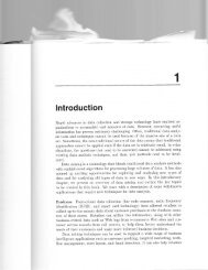
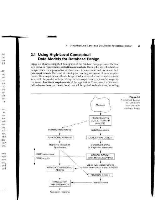
Figure 3.1 shows a simplified description of the database design process. The first<br />
step shown is requirements collection and analysis. During <strong>this</strong> step, the database<br />
designers interview prospective database users to understand and document their<br />
data requirements. The result of <strong>this</strong> step is a concisely written set of users' requirements.<br />
These requirements should be specified in as detailed and complete a form<br />
as possible. In parallel with specifring the data requirements, it is useful to specify<br />
the known functional requirements of the application. These consist of the userdefined<br />
operations (or transactions) that will be applied to the database, including<br />
Functional Requirements<br />
+<br />
@ +<br />
DBMS-independent<br />
I DBMS-specific<br />
I<br />
High-Level Transaction<br />
Specification<br />
Application Programs<br />
@<br />
@<br />
REOUIREMENTS<br />
COLLECTION AND<br />
ANALYSIS<br />
Data Requirements<br />
t<br />
V<br />
Conceptual Schema<br />
(ln a high-level data model)<br />
+<br />
| (DATA MODEL MAPPTNG) |<br />
V<br />
Logical (Conceptual) Schema<br />
-<br />
(ln the data model of a specific DBMS)<br />
ernal Schema<br />
Figure 3.1<br />
A simplified diagram<br />
to illustrate the<br />
main phases of<br />
t^+^f,^^^ t^^i^^<br />
udr4uass uE>19il.