Additional operating instructions Solar module incl ... - Novoferm
Additional operating instructions Solar module incl ... - Novoferm
Additional operating instructions Solar module incl ... - Novoferm

Create successful ePaper yourself
Turn your PDF publications into a flip-book with our unique Google optimized e-Paper software.
<strong>Additional</strong> <strong>operating</strong> <strong>instructions</strong><br />
for VivoPort K3 door systems<br />
<strong>Solar</strong> <strong>module</strong> <strong>incl</strong>. charging regulator<br />
Art. No.: 80 805 223<br />
Only to use as a supplement to the additional installation <strong>instructions</strong> for VivoPort K3 door<br />
systems!<br />
Laying and installing connection cable<br />
Pull the open cable end through any needed drill holes or openings of your garage and<br />
roughly lay the cable as envisaged in the final position.<br />
Caution: Do not as yet insert the cable into the battery pack! The open cable end could<br />
produce a short-circuit which would destroy the battery pack!<br />
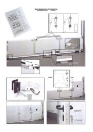
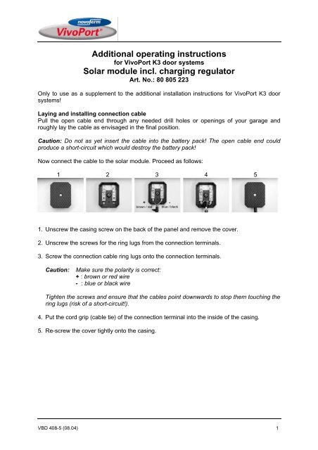
Now connect the cable to the solar <strong>module</strong>. Proceed as follows:<br />
1 2 3 4 5<br />
+<br />
brown / red<br />
1. Unscrew the casing screw on the back of the panel and remove the cover.<br />
2. Unscrew the screws for the ring lugs from the connection terminals.<br />
3. Screw the connection cable ring lugs onto the connection terminals.<br />
Caution: Make sure the polarity is correct:<br />
+ : brown or red wire<br />
- : blue or black wire<br />
Tighten the screws and ensure that the cables point downwards to stop them touching the<br />
ring lugs (risk of a short-circuit!).<br />
4. Put the cord grip (cable tie) of the connection terminal into the inside of the casing.<br />
5. Re-screw the cover tightly onto the casing.<br />
-<br />
blue / black<br />
VBD 408-5 (08.04) 1
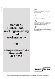
Fitting retaining clips<br />
The retaining clips must now be fitted. Firstly insert the supplied cylinder screws with a<br />
washer, as shown, into the drill holes of the retaining clips. Then push a lock washer onto the<br />
screw and twist a nut onto the screw. Make sure you only loosely fix the nut by just turning<br />
twice.<br />
Gently place the solar <strong>module</strong> – as shown – on a soft surface and fit the retaining clips. Note<br />
that the retaining clips must be fitted on the right sides so they are flush with the panel<br />
aluminium frame. For fitting purposes, place the screws of the retaining clips into the large<br />
opening of the slots. Then push the retaining clip upwards into the upper, narrow part of the<br />
slot. In so doing, ensure that the lock washer is seated under the aluminium frame of the<br />
solar <strong>module</strong>. (see illustration).<br />
Now tightly screw on the retaining clips. In so doing, hold down the nuts by hand until the<br />
lock washer stops them from also being turned.<br />
The solar <strong>module</strong> is now completely fitted and can be set up.<br />
VBD 408-5 (08.04) 2
Instructions on setting up the solar <strong>module</strong><br />
At all events, the solar <strong>module</strong> must be aligned to face south. And this at an angle of approx.<br />
30°. This angle is pre-determined by the support mounting.<br />
Choose a site where the solar <strong>module</strong> is not affected by the shadows of trees, buildings,<br />
chimneys or aerials. Even shadows of short duration can lead to considerable solar <strong>module</strong><br />
yield losses. Shadows can have a negative impact on proper functioning of the door<br />
operator.<br />
The solar <strong>module</strong> can be directly secured to any building wall facing south. However, the<br />
recommendation is usually to mount the solar <strong>module</strong> on a paving slab and place the panel<br />
on the garage roof (see installation example)<br />
With installation, make sure that the solar <strong>module</strong> is not in water given heavy rainfall (e.g.<br />
puddles on the roof). Any rain falling must drain off immediately.<br />
Ensure that the position is firm and stable. Never set up the solar <strong>module</strong> without additional<br />
fastening.<br />
Check regularly to see if the solar <strong>module</strong>, for instance, is covered by leaves or is dirty. In<br />
such an instance, carefully clean the surface with a moist cloth.<br />
Connection to the battery pack<br />
The battery pack can be connected once the solar <strong>module</strong> is<br />
fully installed. Insert the solar <strong>module</strong> plug into the left-hand side<br />
"charging" socket of the battery pack. If the sunlight is intensive<br />
enough, the battery of the pack will be re-charged.<br />
Installation example,<br />
illustration similar<br />
Note: The charging control light of the battery pack only operates given charging from a 230<br />
V mains supply. An optical charging check under solar operations is not possible!<br />
Following installation of the operator and solar <strong>module</strong>, the battery pack should firstly be<br />
completely charged from the 230V mains supply.<br />
Note: The generated energy of the solar <strong>module</strong> might not suffice during the dark winter<br />
months or under unfavourable installation conditions. In this case, the battery pack needs to<br />
be charged or re-charged with the help of a 230V mains supply.<br />
VBD 408-5 (08.04) 3
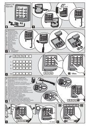
Checking the solar <strong>module</strong> function<br />
To check on the function of the solar <strong>module</strong>, proceed as follows:<br />
Pull the solar <strong>module</strong> plug from the battery pack and hold the testing tips of a voltage meter<br />
(voltmeter or multi-meter) on Pin 1 (+) and Pin 3 (-) of the solar <strong>module</strong> plug (see<br />
illustrations). Depending on the sunlight available at the time, the meter must show a voltage<br />
of between approx. +6V and +14V. The charging regulator integrated in the connection cable<br />
may result in the gauged voltage pulsating.<br />
Pin 1: plus pole +<br />
Pin 3: minus pole -<br />
+<br />
-<br />
Technical data<br />
<strong>Solar</strong> <strong>module</strong> <strong>incl</strong>. charging regulator, Art. No.: 80 805 223<br />
Output: 5.2Wp<br />
Imax: 309mA<br />
Uout: 14.2V<br />
+<br />
red black<br />
Connection cable: Length 8m, charging regulator is integrated in the connection cable<br />
Panel dimensions: 330mm x 293mm (without support mounting)<br />
Weight: approx. 1.6kg<br />
Mounting angle: approx. 30° (pre-determined by support mounting)<br />
Ground and wall fastenings can also be supplied with the mounting support.<br />
VBD 408-5 (08.04) 4<br />
-