Laying the NIBRA® hollow interlocking tile H 10. - Nelskamp
Laying the NIBRA® hollow interlocking tile H 10. - Nelskamp
Laying the NIBRA® hollow interlocking tile H 10. - Nelskamp

Create successful ePaper yourself
Turn your PDF publications into a flip-book with our unique Google optimized e-Paper software.
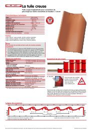
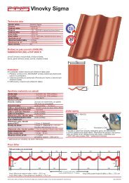
Ridge/crest details<br />
The height of <strong>the</strong> ridge/crest<br />
lath is determined by <strong>the</strong><br />
customer.<br />
Nominal cross-section<br />
at least 24 x 48 mm<br />
Ridge lath holder<br />
Ridge/crest clip<br />
No. 470/41<br />
Ridge <strong>tile</strong>s should be fastened to <strong>the</strong> furring.<br />
Requirement: 1 wood screw and 1 clip<br />
Shed roof <strong>tile</strong><br />
Shed roof <strong>tile</strong>s should be fastened<br />
to <strong>the</strong> furring (see detail verge).<br />
Size sheets can<br />
be downloaded<br />
from <strong>the</strong> Internet<br />
or on <strong>the</strong> data<br />
service CD<br />
0,6 kN/m<br />
Copper roll/Alu roll 2000:<br />
Rec. for ridge flap band width 330 mm<br />
(narrow undercover)<br />
Rec. for ridge flap band width 360 mm<br />
(broad undercover)<br />
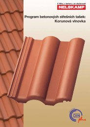
Installation instructions for safety step <strong>tile</strong>/<br />
walking grid <strong>tile</strong>/snow stop <strong>tile</strong><br />
Each ridge <strong>tile</strong>:<br />
wood screw, d = 4.5 mm<br />
screw depth: 24 mm<br />
Every safety step <strong>tile</strong>/walking grid <strong>tile</strong> must be provided with an additional<br />
supporting-safety lath (same lath cross-section as supporting<br />
laths). Fastening to supporting lath: two corrosion-proof wood<br />
screws (4.5 x 45 mm per <strong>tile</strong>)<br />
Processing acc. to DIN 18160-5<br />
Article ≤ 45° > 45°<br />
Walking grid every every<br />
<strong>tile</strong> row of <strong>tile</strong>s row of <strong>tile</strong>s<br />
Safety every every<br />
step <strong>tile</strong> row of <strong>tile</strong>s row of <strong>tile</strong>s<br />
tested to DIN EN 516<br />
depending on roof pitch<br />
from 100 to 285 mm<br />
Supporting-safety lath<br />
from width of<br />
verge side to 340 mm<br />
Aeration/venting<br />
90° • maximum lath size of 285 mm<br />
• minimum lath size of 100 mm<br />
80°= RP 10° • maximum lath size of 255 mm<br />
• minimum lath size of 100 mm<br />
70°= RP 20° • maximum lath size of 235 mm<br />
• minimum lath size of 100 mm<br />
60°= RP 30° • maximum lath size of 205 mm<br />
• minimum lath size of 100 mm<br />
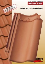
Mansard and pent roof <strong>tile</strong><br />
B<br />
A<br />
C<br />
Size sheets can be downloaded<br />
from <strong>the</strong> Internet or on <strong>the</strong><br />
data service CD<br />
The same applies for <strong>interlocking</strong> <strong>tile</strong>s with snow rib or round wood<br />
holder, whereby <strong>the</strong> max. support spacing should not exceed 90 cm.<br />
For higher demands you should reduce <strong>the</strong> support spacing (60 cm).<br />
Subject to technical changes. The dimensions are planning figures and should be checked before laying.<br />
60°<br />
70°<br />
E<br />
80°<br />
D<br />
F<br />
90°<br />
Roof lath 2 x<br />
fastening in <strong>the</strong><br />
counter-lath<br />
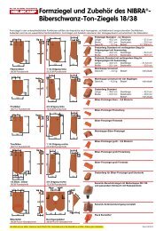
Verge details<br />
Also applies for <strong>the</strong> verge<br />
<strong>tile</strong> with outer web and<br />
double flap!<br />
The screw connection<br />
in <strong>the</strong> verge should<br />
have a permanently<br />
elastic seal particularly<br />
for flat roof pitches<br />
(e.g. plumber screws)<br />
Projects at least 3 cm over outer edge gable wall.<br />
Projects at least 1cm over wooden structure.<br />
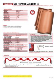
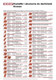
Aeration and ventilation in steep roof<br />
1<br />
2<br />
3<br />
1<br />
0,6 kN/m<br />
Eaves fresh air element<br />
Copper roll/Alu roll 2000<br />
Clay dormer ventilator<br />
with fitted screen<br />
vent cross-section<br />
~ 17 cm 2<br />
2<br />
Counter-laths<br />
Underlay/undercover sheet<br />
Eaves fresh air element<br />
1) The vent cross-section at <strong>the</strong> eaves should be at least<br />
200 cm2 /m of eaves.<br />
2) The vent cross-section at <strong>the</strong> ridge or crest should be at least<br />
0.5‰ of <strong>the</strong> total corresponding roof area, though at least 50 cm2 .<br />
(according to DIN 4108-3)<br />
Storm clips<br />
On <strong>the</strong> NELSKAMP data service CD<br />
or as a download on <strong>the</strong> Internet from<br />
www.nelskamp.de<br />
• Product specifications<br />
• <strong>Laying</strong> instructions<br />
• CAD data<br />
3<br />
Each verge <strong>tile</strong>:<br />
wood screw, d = 4.5 mm<br />
screw depth: 24 mm<br />
Installation instructions for universal walking grid<br />
A chase is made in <strong>the</strong> head and<br />
foot <strong>interlocking</strong> joint of <strong>the</strong> gutter<br />
<strong>tile</strong> using a right angle grinder with<br />
diamond wheel to lead through <strong>the</strong><br />
stainless steel suspension hinge.<br />
Hang <strong>the</strong> alu mounting bracket in<br />
<strong>the</strong> throat of <strong>the</strong> gutter <strong>tile</strong> so that<br />
<strong>the</strong> two rubber profiles with <strong>the</strong><br />
lower end of <strong>the</strong> mounting bracket<br />
lie on <strong>the</strong> roof lath.<br />
The rubber profiles must rest<br />
where <strong>the</strong> gutter <strong>tile</strong>s overlap.<br />
Installation instructions on delivery<br />
No. 435/101 for laths 30 x 50 V2A<br />
No. 435/102 for laths 40 x 60 V2A<br />
can be adjusted for roof<br />
pitches from 0° - 60°<br />
No. 409/009 V2A<br />
walking grid<br />
Mounting<br />
bracket<br />
Stainless steel<br />
suspension hinge<br />
tested to<br />
DIN EN 516<br />
According to professional standards, we can supply storm clips for a simple<br />
and effective protection against wind suction. They can alternatively be<br />
clipped to <strong>the</strong> laths or knocked into <strong>the</strong> laths. Resistant to corrosion through<br />
stainless steel wire 1.4301 (A2) or ZIAL ® coating (corrosion protection).