10" TILTING ARBOR SAW Model 66 - MIS Group, Inc.
10" TILTING ARBOR SAW Model 66 - MIS Group, Inc.
10" TILTING ARBOR SAW Model 66 - MIS Group, Inc.

Create successful ePaper yourself
Turn your PDF publications into a flip-book with our unique Google optimized e-Paper software.
6 Loosely install the 5/16" x 1-1/4" screws with flat<br />
washers, lock washers and nuts into the rear side of<br />
extension table Loosely install the 1/4" x 1-1/2"<br />
screws with lock washers and nuts into the front side<br />
of extension table<br />
7 Recheck that the table is level and tighten all<br />
screws<br />
<strong>SAW</strong> ADJUSTMENTS<br />
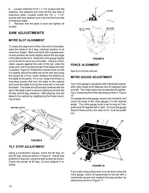
MITRE SLOT ALIGNMENT<br />
To check the alignment of the mitre slot to the blade,<br />
raise the blade to its 0 deg (vertical) position to its<br />
maximum height Mark one tooth with a grease pencil<br />
and position the tooth slightly above the top edge<br />
of the table at the front Raise the mitre gauge slightly<br />
out of its slot to serve as a shoulder Using a combination<br />
square against the side of the bar, slide the<br />
scale over until it touches the tip of the blade and lock<br />
in position, Figure 8 Rotate the marked tooth so that<br />
it is slightly above the table top at the rear and using<br />
the square as in front, check whether the distance to<br />
the blade is the same If it is not, loosen the three (3)<br />
mounting screws that lock the table to the cabinet<br />
and move the table to bring the mitre slot in line with<br />
the blade The blade should be kept centered with the<br />
slot in the table insert to ensure clearance at both the<br />
90 deg and 45 deg positions After aligning, lock the<br />
table to the cabinet by retightening the three mounting<br />
screws<br />
FIGURE 9<br />
FENCE ALIGNMENT<br />
See Accu-Fence manual<br />
MITRE GAUGE ADJUSTMENT<br />
Your mitre gauge is equipped with individually adjustable<br />
index stops at 90 degrees and 45 degrees right<br />
and left The index stops can be adjusted by tightening<br />
or loosening the three adjusting screws A, Figure<br />
10<br />
To operate the mitre gauge, loosen lock handle B, and<br />
move the body of the mitre gauge C to the desired<br />
angle The mitre gauge body is set to stop at 0 degrees<br />
and 45 degrees left or right To move the gauge<br />
beyond these points, the stop rod D, must be pulled<br />
out<br />
FIGURE 8<br />
TILT STOP ADJUSTMENT<br />
Using a combination square, check the 90 deg (0)<br />
and 45 deg stops as shown in Figure 9 Adjust stop<br />
positions if required, using the stop screws as shown<br />
Check the pointer at 90 deg (0) and readjust if required<br />
FIGURE 10<br />
If accurate crosscutting work is to be done using the<br />
mitre gauge, check its squareness to the slot with a<br />
machinists square and readjust the stop position as<br />
required as shown in Figure 11<br />
10