10" TILTING ARBOR SAW Model 66 - MIS Group, Inc.
10" TILTING ARBOR SAW Model 66 - MIS Group, Inc.
10" TILTING ARBOR SAW Model 66 - MIS Group, Inc.

You also want an ePaper? Increase the reach of your titles
YUMPU automatically turns print PDFs into web optimized ePapers that Google loves.
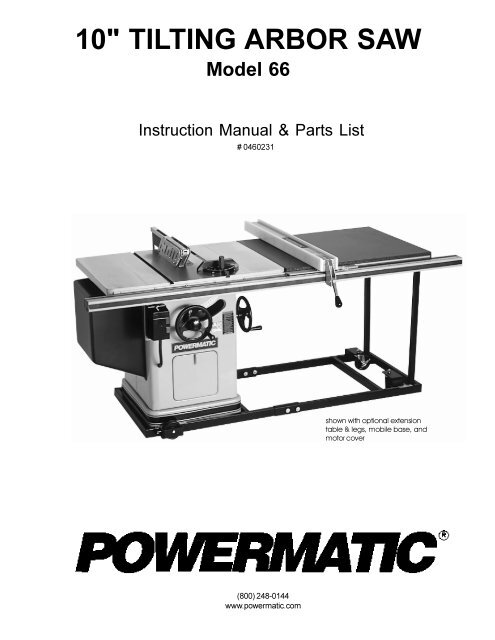
10" <strong>TILTING</strong> <strong>ARBOR</strong> <strong>SAW</strong><br />
<strong>Model</strong> <strong>66</strong><br />
Instruction Manual & Parts List<br />
# 0460231<br />
shown with optional extension<br />
table & legs, mobile base, and<br />
motor cover<br />
(800) 248-0144<br />
wwwpowermaticcom
This manual has been prepared for the owner and operators of a Powermatic <strong>Model</strong> <strong>66</strong> Tilting<br />
Arbor Table Saw Its purpose, aside from machine operation, is to promote safety through the<br />
use of accepted correct operating and maintenance procedures Completely read the safety<br />
and maintenance instructions before operating or servicing the machine To obtain maximum<br />
life and efficiency from your table saw and to aid in using the machine safely, read this manual<br />
thoroughly and follow all instructions carefully<br />
Warranty & Service<br />
The JET <strong>Group</strong> warrants every product it sells If one of our tools needs service or repair, one of our Authorized<br />
Repair Stations located throughout the United States can give you quick service<br />
In most cases, any one of these JET <strong>Group</strong> Repair Stations can authorize warranty repair, assist you in<br />
obtaining parts, or perform routine maintenance and major repair on your JET, Performax or Powermatic tools<br />
For the name of an Authorized Repair Station in your area, please call 1-800-274-6848<br />
More Information<br />
Remember, the JET <strong>Group</strong> is consistently adding new products to the line For complete, up-to-date product<br />
information, check with your local JET <strong>Group</strong> distributor<br />
JET <strong>Group</strong> Warranty<br />
The JET <strong>Group</strong> (including Performax and Powermatic brands) makes every effort to assure that its products<br />
meet high quality and durability standards and warrants to the original retail consumer/purchaser of our products<br />
that each product be free from defects in materials and workmanship as follow: 1 YEAR LIMITED WAR-<br />
RANTY ON ALL PRODUCTS UNLESS SPECIFIED OTHERWISE This Warranty does not apply to defects<br />
due directly or indirectly to misuse, abuse, negligence or accidents, normal wear-and-tear, repair or alterations<br />
outside our facilities, or to a lack of maintenance<br />
THE JET GROUP LIMITS ALL IMPLIED WARRANTIES TO THE PERIOD SPECIFIED ABOVE, FROM THE<br />
DATE THE PRODUCT WAS PURCHASED AT RETAIL EXCEPT AS STATED HEREIN, ANY IMPLIED WAR-<br />
RANTIES OR MERCHANTIBILITY AND FITNESS ARE EXCLUDED SOME STATES DO NOT<br />
ALLOW LIMITATIONS ON HOW LONG THE IMPLIED WARRANTY LASTS, SO THE ABOVE LIMITATION MAY<br />
NOT APPLY TO YOU THE JET GROUP SHALL IN NO EVENT BE LIABLE FOR DEATH, INJURIES TO<br />
PERSONS OR PROPERTY, OR FOR INCIDENTAL, CONTINGENT, SPECIAL, OR CONSEQUENTIAL DAM-<br />
AGES ARISING FROM THE USE OF OUR PRODUCTS SOME STATES DO NOT ALLOW THE EXCLUSION<br />
OR LIMITATION OF INCIDENTAL OR CONSEQUENTIAL DAMAGES, SO THE ABOVE LIMITATION OR EX-<br />
CLUSION MAY NOT APPLY TO YOU<br />
To take advantage of this warranty, the product or part must be returned for examination, postage prepaid, to an<br />
Authorized Repair Station designated by our office Proof of purchase date and an explanation of the complaint<br />
must accompany the merchandise If our inspection discloses a defect, we will either repair or replace the<br />
product, or refund the purchase price if we cannot readily and quickly provide a repair or replacement, if you are<br />
willing to accept a refund We will return repaired product or replacement at JET's expense, but if it is determined<br />
there is no defect, or that the defect resulted from causes not within the scope of JET's warranty, then<br />
the user must bear the cost of storing and returning the product This warranty gives you specific legal rights;<br />
you may also have other rights which vary from state to state<br />
The JET <strong>Group</strong> sells through distributors only Members of the JET <strong>Group</strong> reserve the right to effect at any<br />
time, without prior notice, those alterations to parts, fittings, and accessory equipment which they may deem<br />
necessary for any reason whatsoever
TABLE OF CONTENTS<br />
Safety:<br />
General Rules 4<br />
Specific Rules 5<br />
Decal Instruction 6<br />
Specifications 7<br />
Receiving the <strong>66</strong> TA Saw 8<br />
Installation and Assembly<br />
Lock Knobs 8<br />
Extension Wings 8<br />
Rails & Accu-Fence 8<br />
Mounting Blade 8<br />
Splitter and Guard Assembly 8<br />
Mitre Gauge 9<br />
Motor Cover (Optional) 9<br />
Formica Top Extension Table (Optional) 9<br />
Saw Adjustments<br />
Mitre Slot Adjustment 10<br />
Tilt Stop Adjustment 10<br />
Fence Alignment 10<br />
Mitre Gauge Adjustment 10<br />
Belt Tensioning 11<br />
Arbor and Arbor Bearing Removal 11<br />
Blade Raising Mechanism Adjustment 11<br />
Splitter Alignment 11<br />
Insert Adjustment 12<br />
Changing Saw Blades 12<br />
Tilting Mechanism Adjustment 12<br />
General Maintenance 12<br />
Trouble Shooting Tips 13<br />
Featherboard Construction 14<br />
Filler Piece Construction 14<br />
Push Stick and Push Block Construction 14<br />
Parts Lists and Exploded Views:<br />
Splitter and Guard Assembly 15<br />
Stand Assembly 16-17<br />
Optional Table Extension and Legs 15<br />
Trunnion Assembly 18-19<br />
Mitre Gauge 20<br />
Controls 21<br />
Optional Accessories 21<br />
Electrical:<br />
NHD: 3 HP, 1 Ph, 230V 22<br />
NHD: 5 HP, 1 Ph, 230V 23<br />
NHD: 5 HP, 3 Ph, 230V 24<br />
NHD: 5 HP, 3 Ph, 460V 25
!<br />
SAFETY RULES<br />
As with all machines, there is a certain amount of hazard involved with the use of this table saw Use the<br />
machine with the respect and caution demanded where safety precautions are concerned When normal<br />
safety precautions are overlooked or ignored, personal injury to the operator can result<br />
Read, understand and follow the safety and operating instructions found in this manual Know the limitations<br />
and hazards associated with this table saw<br />
Electrical grounding Make certain that the machine frame is electrically grounded and that a ground lead is<br />
included in the incoming electrical service In cases where a cord and plug are used, make certain that the<br />
grounding plug connects to a suitable ground Follow the grounding procedure indicated in the National Electrical<br />
Code<br />
Eye safety Wear an approved safety shield, goggles, or glasses to protect eyes (NOTE: Common eyeglasses<br />
are not safety glasses)<br />
Personal protection Before operating the machine, remove tie, rings, watch and other jewelry and roll up<br />
sleeves above the elbows Remove all loose outer clothing and confine long hair Protective type footwear<br />
should be used Where the noise exceeds the level of exposure allowed in Section 191095 of the OSHA<br />
Regulations, use hearing protective devices Do not wear gloves<br />
Guards Keep the machine guards in place for every operation for which they can be used If any guards are<br />
removed for maintenance, DO NOT OPERATE the machine until the guards are reinstalled<br />
Work area Keep the floor around the machine clean and free of scrap material, saw dust, oil and other liquids<br />
to minimize the danger of tripping or slipping Be sure the table is free of all scrap, foreign material and tools<br />
before starting to cut Make certain the work area is well lighted and that a proper exhaust system is used to<br />
minimize dust Powermatic recommends the use of anti-skid floor strips on the floor area where the operator<br />
normally stands and that each machine’s work area be marked off Provide adequate work space around the<br />
machine<br />
Operator position Maintain a balanced stance and keep your body under control at all times Do not stand<br />
in line with the saw blade or work piece and do not allow anyone else to do so Never climb on or near the saw<br />
Do not overreach Use a support table or have a helper or “tailman” take stock away from the back side of<br />
the blade<br />
Housekeeping Before turning on machine, remove all extra equipment such as keys, wrenches, scrap, and<br />
cleaning rags away from the saw<br />
Careless acts Give the work you are doing your undivided attention Looking around, carrying on a conversation,<br />
and “horseplay” are careless acts that can result in serious injury<br />
Disconnect machine before performing any service or maintenance or when changing blades A machine<br />
under repair should be RED TAGGED to show it should not be used until the maintenance is complete<br />
Alignment Check the alignment of the splitter, fence and miter slot to the blade A caution decal is installed<br />
on each guard and splitter to remind the operator of the dangers of misalignment<br />
Maintain tools in top condition Check the saw blade for cracks or missing teeth Do not use a cracked or<br />
dull blade or one with missing teeth or improper set Make sure the blade is securely locked on the arbor<br />
Hand safety Keep hands clear of the blade area Do not reach past the blade to clear parts or scrap with the<br />
saw blade running Never saw free hand Avoid awkward operations and hand positions where a sudden slip<br />
could cause your hand to contact the blade<br />
4
Safety devices Always use the splitter, blade guard, push stick and other safety devices for all operations<br />
where they can be used On operations such as dadoing or molding where the blade guard cannot be used,<br />
use feather boards (see page 14), fixtures and other safety devices and use extreme caution Reinstall the<br />
splitter and blade guard immediately after completing the operation that required their removal<br />
Saw blade rotation Be sure the saw blade rotates clockwise when viewed from the motor side (left side) of<br />
the machine<br />
Adjustments Make all adjustments to the machine and operational setup with the power off Never remove<br />
the insert with the blade running<br />
Material condition Do not attempt to saw boards with loose knots or with nails or other foreign material, on<br />
its surface Do not attempt to saw twisted, warped, bowed or “in wind” stock unless one edge has been<br />
jointed for guiding purposes prior to sawing<br />
Large stock Do not attempt to saw long or wide boards unsupported where spring or weight could cause the<br />
board to shift position<br />
Job completion If the operator leaves the machine area for any reason, he should turn “off” the power to the<br />
table saw motor and wait until the saw blade comes to a complete stop before his departure In addition, if the<br />
operation is complete, he should clean the table saw and the work area NEVER clean off the table saw with<br />
power “on” and NEVER use the hands to clear sawdust and debris; use a brush<br />
Replacement parts Use only Powermatic or factory authorized replacement parts and accessories; otherwise<br />
the table saw warranty and guarantee is null and void<br />
Misuse Do not use this Powermatic table saw for other than its intended use If used for other purposes,<br />
Powermatic disclaims any real or implied warranty and holds itself harmless for any injury or damage which<br />
may result from that use Do not equip this table saw with a motor larger than five (5) horsepower at 3600<br />
RPM Doing so voids the warranty and Powermatic holds itself harmless from any injury which may result<br />
If you are not thoroughly familiar with the operation of Table Saws, obtain advice from your supervisor, instructor<br />
or other qualified person<br />
Drugs, alcohol, medication Do not operate this machine while under the influence of drugs, alcohol, or any<br />
medication<br />
Health hazards Some dust created by power sanding, sawing, grinding, drilling and other construction<br />
activities contains chemicals known to cause cancer, birth defects or other reproductive harm Some examples<br />
of these chemicals are:<br />
* Lead from lead-based paint<br />
* Crystalline silica from bricks and cement and other masonry products<br />
* Arsenic and chromium from chemically-treated lumber<br />
Your risk from these exposures varies, depending on how often you do this type of work To reduce your<br />
exposure to these chemicals, work in a well-ventilated area, and work with approved safety equipment, such<br />
as those dust masks that are specifically designed to filter out microscopic particles<br />
Familiarize yourself with the following safety notices used in this manual:<br />
!<br />
!<br />
CAUTION: (This means that if precautions are not heeded, it may result in minor or moderate injury<br />
and/or possible machine damage)<br />
WARNING: (This means that if precautions are not heeded, it could result in serious injury or<br />
possibly even death)<br />
5
SAFETY DECAL<br />
FIGURE 1<br />
6
SPECIFICATIONS<br />
FIGURE 2<br />
Table with Standard Extensions 28" x 38"<br />
Rip Fence 2-1/2" x 4" x 41-3/4"<br />
Arbor Diameter 5/8"<br />
Saw Blade Diameter 10"<br />
Blade Tilt Maximum 45 Deg<br />
Maximum Depth of Cut 90 DEG: 3-1/8"; 45 DEG: 2-1/8"<br />
Maximum Cut with Standard Extension to Right of Saw Blade 25"<br />
Maximum Width of Cutoff in Front of Saw in 1" Stock 15"<br />
Maximum Width of Cutoff in Front of Saw in 3-1/8" Stock 12-1/4"<br />
Maximum width of Dado Cut 13/16"<br />
Maximum Motor 5 HP 3600 RPM<br />
Maximum Speed of 10" Saw Blade 11,000 SFM<br />
Drive Belts 3VX (two required)<br />
Table Height to Floor 34"<br />
Dust Collection Outlet 4"<br />
Shipping Weight with Motor, Fence & Rails 614 lbs<br />
NOTE: The above specifications were current at the time this manual was published, but because of our policy<br />
of continuous improvement, Powermatic reserves the right to change specifications without notice and without<br />
incurring obligations<br />
7
RECEIVING THE <strong>SAW</strong><br />
Open shipping container and all separate cartons containing<br />
rails and accessories Report any damage<br />
immediately to your distributor Read the instruction<br />
manual thoroughly for assembly, alignment, maintenance<br />
and safety instructions<br />
Box contents:<br />
Box 1: table saw, extension wings, manuals<br />
Box 2: (shipped inside Box 1): splitter and guard<br />
assembly, splitter support shaft, arbor wrench,<br />
lock knobs, miter gauge, hardware bag<br />
Box 3: Accu-Fence, lock handle, manual<br />
Box 4: Front & rear rails, guide tube, hardware bag<br />
Optional:<br />
Box 5: Motor cover & screws<br />
Box 6: Formica top extension table<br />
Box 7: Legs for ext table<br />
INSTALLATION AND ASSEMBLY<br />
Tools required for assembly:<br />
9/16" wrench<br />
or one open end<br />
7/16" wrench<br />
adjustable wrench<br />
1/2" wrench<br />
7/32" hex head (allen) wrench<br />
3/32" hex head (allen) wrench<br />
Flat head screwdriver (for electrical<br />
connections)<br />
1 Remove all wood crating from around the saw<br />
2 With a 9/16" wrench, remove the bolt holding the<br />
extension wings together and set wings aside for later<br />
installation<br />
3 With a 7/16" wrench, remove the two hex head<br />
screws holding the saw to the wooden skid Carefully<br />
slide the saw from the pallet onto the floor<br />
4 Tilt the saw, and pop off the metal tabs that secured<br />
the saw to the skid, by pushing down on them<br />
NOTE: Exposed metal parts such as the top and extension<br />
wings have been given a protective coating at<br />
the factory This should be removed with a solvent<br />
(such as mineral spirits) once the machine has been<br />
assembled<br />
LOCK KNOBS<br />
1 With a 7/32" allen wrench, check the factory tightness<br />
of the setscrews in the handwheels, Figure 3,<br />
making sure the setscrews are tightened in the middle<br />
of the flats on each shaft The hand-wheel should be<br />
flush with the end of the shaft<br />
8<br />
FIGURE 3<br />
2 Find the two lock knob assemblies Check that<br />
the setscrews in the knobs are tight using a 3/32"<br />
allen wrench Screw one knob assembly, Figure 3,<br />
into the tilting mechanism hand-wheel and the other<br />
into the handwheel for raising and lowering the blade<br />
EXTENSION WINGS<br />
1 Mount the cast iron extension wings using the<br />
(6) 3/8" x 1" hex head screws and lock washers Holding<br />
the wing in upright position to the saw table, insert<br />
the middle screw and lock washer first but do not<br />
tighten completely<br />
2 Pivot the wing to level position and insert the<br />
outside screws Do not tighten completely<br />
3 Level the extension wing with the table, using a<br />
straight edge Make sure the edges are even with the<br />
edges of the table top<br />
4 Tighten all screws<br />
MOUNTING BLADE<br />
If your blade came uninstalled, refer to "Changing Saw<br />
Blades," page 12 NOTE: Blade should be mounted<br />
first before rails are adjusted<br />
RAILS & ACCU-FENCE<br />
(Refer to the manual that accompanies the Accu-Fence<br />
to assemble rails and fence at this point)<br />
NOTE: If you are installing the optional formica top<br />
extension table, it should be mounted before installing<br />
the guide tube<br />
SPLITTER AND GUARD ASSEMBLY<br />
1 Insert the grooved end of the splitter support shaft<br />
through slot in rear of saw and into hole in trunnion,<br />
Figure 4 Make sure the square head setscrew is<br />
backed out enough to allow easy insertion<br />
2 With a wrench, tighten square head setscrew<br />
into the groove of the shaft as shown in Figure 4<br />
(NOTE: The groove will be in the proper position if the<br />
end of the shaft is made flush with the opposite side of<br />
the trunnion hole) Tighten the locknut The upright<br />
member of the rear splitter support must be on the left<br />
side of the saw (observed from the saw's front)
MOTOR COVER (OPTIONAL)<br />
1 If your saw came with the optional motor cover,<br />
find the two 1/4"-20 self tapping sheet metal screws<br />
and install them in the punched holes on the saw cabinet<br />
Do not screw down all the way, but leave the heads<br />
about 1/4" from the surface<br />
2 Lift the motor cover over these screws with the<br />
cover's bottom lip inside the saw's cabinet<br />
3 Tighten the two screws<br />
FIGURE 4<br />
3 Mount the splitter assembly to the two adjusting<br />
screws, Figure 5 Place the two flanges of the splitter<br />
assembly onto the screws as shown<br />
4 The splitter and guard assembly must be aligned<br />
with the blade Adjust the splitter according to the directions<br />
on page 11, "Splitter Alignment"<br />
FORMICA TOP EXTENSION TABLE<br />
(OPTIONAL)<br />
NOTE: The extension table should be installed before<br />
the guide tube After the extension table is mounted,<br />
the fence can be adjusted and the guide tube installed<br />
Tools needed:<br />
Electric drill (3/32", 5/16" and 1/4" bits)<br />
wrench<br />
The extension table will be bolted to the rails:<br />
1 Lay the extension table on the floor, on the edge<br />
where the legs will be attached Put the leg brackets<br />
inside the top's bracing Block up legs so they will lay<br />
in the bracing and be parallel to the floor, Figure 7<br />
FIGURE 5<br />
MITRE GAUGE<br />
Place washer on threaded rod, Figure 6, and screw<br />
the handle on to the bolt Install the mitre gauge in its<br />
left hand slot on the table<br />
FIGURE 6<br />
FIGURE 7<br />
2 Mark where the screws are to be installed Drill a<br />
3/32" pilot hole and install the screws<br />
3 Position the table inside the rails and up against<br />
the cast iron wing, and level it with the cast iron wing<br />
using a straightedge Use clamps if necessary to hold<br />
table in position Adjust the foot pads in or out as<br />
needed to make extension table level When level, use<br />
the fence holes as your guide to drill the holes in the<br />
table or, mark the location of holes and remove the<br />
table for drilling<br />
(NOTE: The extension table is mounted to the predrilled<br />
holes in the fence; it is not bolted to the cast<br />
iron saw table)<br />
4 For the side against the rear rail, drill pilot holes<br />
and then drill 5/16" holes<br />
5 For the side against the front rail, drill pilot holes<br />
and then drill 1/4" holes<br />
9
6 Loosely install the 5/16" x 1-1/4" screws with flat<br />
washers, lock washers and nuts into the rear side of<br />
extension table Loosely install the 1/4" x 1-1/2"<br />
screws with lock washers and nuts into the front side<br />
of extension table<br />
7 Recheck that the table is level and tighten all<br />
screws<br />
<strong>SAW</strong> ADJUSTMENTS<br />
MITRE SLOT ALIGNMENT<br />
To check the alignment of the mitre slot to the blade,<br />
raise the blade to its 0 deg (vertical) position to its<br />
maximum height Mark one tooth with a grease pencil<br />
and position the tooth slightly above the top edge<br />
of the table at the front Raise the mitre gauge slightly<br />
out of its slot to serve as a shoulder Using a combination<br />
square against the side of the bar, slide the<br />
scale over until it touches the tip of the blade and lock<br />
in position, Figure 8 Rotate the marked tooth so that<br />
it is slightly above the table top at the rear and using<br />
the square as in front, check whether the distance to<br />
the blade is the same If it is not, loosen the three (3)<br />
mounting screws that lock the table to the cabinet<br />
and move the table to bring the mitre slot in line with<br />
the blade The blade should be kept centered with the<br />
slot in the table insert to ensure clearance at both the<br />
90 deg and 45 deg positions After aligning, lock the<br />
table to the cabinet by retightening the three mounting<br />
screws<br />
FIGURE 9<br />
FENCE ALIGNMENT<br />
See Accu-Fence manual<br />
MITRE GAUGE ADJUSTMENT<br />
Your mitre gauge is equipped with individually adjustable<br />
index stops at 90 degrees and 45 degrees right<br />
and left The index stops can be adjusted by tightening<br />
or loosening the three adjusting screws A, Figure<br />
10<br />
To operate the mitre gauge, loosen lock handle B, and<br />
move the body of the mitre gauge C to the desired<br />
angle The mitre gauge body is set to stop at 0 degrees<br />
and 45 degrees left or right To move the gauge<br />
beyond these points, the stop rod D, must be pulled<br />
out<br />
FIGURE 8<br />
TILT STOP ADJUSTMENT<br />
Using a combination square, check the 90 deg (0)<br />
and 45 deg stops as shown in Figure 9 Adjust stop<br />
positions if required, using the stop screws as shown<br />
Check the pointer at 90 deg (0) and readjust if required<br />
FIGURE 10<br />
If accurate crosscutting work is to be done using the<br />
mitre gauge, check its squareness to the slot with a<br />
machinists square and readjust the stop position as<br />
required as shown in Figure 11<br />
10
BELT TENSIONING<br />
FIGURE 11<br />
The saw is equipped with a set of two matched belts<br />
and on replacement, replace the complete set To<br />
retension the belts, loosen the cap screws on either<br />
side of the motor bracket as shown in Figure 12, and<br />
pivot the motor and bracket to the right Retighten the<br />
mounting screws To remove and re-place the belts,<br />
loosen the mounting screws and rotate the motor and<br />
bracket to the left as far as possible Remove one<br />
belt at a time After installing new belts, retension as<br />
indicated<br />
FIGURE 13<br />
BLADE RAISING MECHANISM<br />
ADJUSTMENT<br />
If binding occurs, clean off all sawdust and pitch buildup<br />
and re-lubricate with a good non-hardening grease such<br />
as Fiske Company Lubriplate If binding continues,<br />
check the fit-up of the worm and worm gear segment<br />
The worm must be centered with the worm gear segment<br />
If it is not centered, loosen the saw raising arm<br />
setscrews and move the arm as required, Figure 14,<br />
and relock If saw arm has been relocated, the table<br />
may have to be realigned so as to provide clearance<br />
between the saw blade and table insert slot and the<br />
splitter will have to be realigned NOTE: The saw arm<br />
setscrew must be tight to avoid the possibility of movement<br />
which could cause the blade to hit the insert<br />
FIGURE 12<br />
<strong>ARBOR</strong> AND <strong>ARBOR</strong> BEARING<br />
REMOVAL<br />
1 To remove the saw arbor, first remove the mounting<br />
screws holding the table top to the base Lift off<br />
the table top<br />
2 Loosen the two setscrews in the motor pulley<br />
and remove the pulley and key<br />
3 Loosen the setscrew at the saw raising arm and<br />
the arbor assembly and bearings will slide out of the<br />
arm housing, Figure 13<br />
FIGURE 14<br />
SPLITTER ALIGNMENT<br />
One of the most critical adjustments to help avoid kickbacks<br />
is the splitter adjustment It should be checked<br />
and readjusted, if required, after each blade change<br />
1 To align the splitter to the blade use a combination<br />
square against the side of the raised up miter<br />
gauge bar and slide the scale against the top of the<br />
tooth, Figure 15<br />
2 Check the splitter for parallelism and for clearance<br />
to the miter slot and readjust if required The insert will<br />
have to be removed to access the adjustment jack<br />
screw mounted in the center trunnion<br />
11
3 Move the miter gauge to the opposite side of the<br />
blade and using the combination square, slide the scale<br />
against the top of the tooth Check for clearance<br />
Clearance should be approximately equal on both sides<br />
of the blade<br />
FIGURE 17<br />
<strong>TILTING</strong> MECHANISM ADJUSTMENT<br />
FIGURE 15<br />
INSERT ADJUSTMENT<br />
Adjust the setscrews as required in the insert, Figure<br />
16, to ensure that the insert is stable and flush with or<br />
slightly below the table top<br />
If binding occurs in the tilting mechanism, clean off<br />
the saw dust and pitch accumulation and regrease If<br />
binding continues, check the alignment and readjust<br />
as required to center of worm with the worm gear segment<br />
on the trunnion If there is excessive play, loosen<br />
cap screws and adjust jack screws (Figure 14) clockwise<br />
to raise pinion A tight mesh without binding is<br />
ideal Retighten mounting screws and check over the<br />
90 degree to 45 degree range of tilt for excessive play<br />
or binding Readjust if required<br />
GENERAL MAINTENANCE<br />
Good saw operation requires periodic preventive maintenance<br />
12<br />
FIGURE 16<br />
CHANGING <strong>SAW</strong> BLADES<br />
To change a saw blade, disconnect machine from<br />
power source Remove the table insert<br />
1 Wedge a block of wood between saw blade and<br />
table to prevent blade from rotating, Figure 17 Place<br />
the arbor wrench on the arbor nut (NOTE: right-hand<br />
threads)<br />
2 Remove the arbor nut and collar and saw blade<br />
Install new blade making sure the cutting edge of the<br />
teeth at the top face toward the front of the saw<br />
3 Slide the collar on the arbor and start the arbor<br />
nut on the threads Snug the arbor nut against the<br />
collar and saw blade using the wrench and holding the<br />
saw blade with the thumb and finger tips<br />
4 Wedge a block of wood between the saw blade<br />
and table and tighten the arbor nut securely Replace<br />
the table insert and reconnect the machine to power<br />
source<br />
Keep the inside of the cabinet and trunnion area clean<br />
A stiff brush will remove sawdust before it cakes and<br />
pitch or gum is easily removed with a commercial solvent<br />
or with a good oven cleaner To accomplish this,<br />
remove the table by removing the three mounting<br />
screws and exposing the working mechanisms of the<br />
saw After cleaning the tilting and raising worm and<br />
worm gear segments and the trunnions, grease these<br />
three areas with a good grade non-hardening grease<br />
such as Fiske Company “Lubriplate”<br />
Check periodically for excessive play in the tilting and<br />
raising mechanism and in the saw arbor and readjust<br />
as required<br />
Check periodically for belt tension and wear Readjust<br />
or replace belt as required<br />
The table surface must be kept clean and free of rust<br />
for best results Although some users prefer a wax<br />
coating, white talcum powder applied with a blackboard<br />
eraser rubbed in vigorously once a week will fill<br />
casting pores and form a moisture barrier This method<br />
provides a table top that is slick and allows rust rings<br />
to be easily wiped from the surface Important also is<br />
the fact that talcum powder will not stain wood or mar<br />
finishes as wax pickup does
TROUBLE SHOOTING TIPS<br />
752 8%/ ( 32<strong>66</strong>,%/ ( &$86( 62/ 87,21<br />
( [FHVVLYHYLEUDWLRQ 7LOWRUUDLVLQJFODP SNQREVQRW<br />
WLJKWHQHG<br />
%ODGHRXWRIEDODQFH<br />
%DGP RWRU<br />
/ RRVHDUERURUP RWRUVKHDYH<br />
&XWRXWRIVTXDUHZKHQ<br />
FURVVFX WLQJ <br />
0RWRUVWD OVRUZRUNSLHFHELQGV<br />
RUEXUQV<br />
0 LWHUJDXJHRXWRIDGMXVWPHQW<br />
0 LWHUVORWP LVDOLJQHG<br />
( [FHVVLYHIHHG<br />
%DGP RWRU<br />
' XORULQFRUUHFWEODGH<br />
0 LWHUVORWP LVDOLJQHG<br />
) HQFHP LVDOLJQP HQW<br />
7LJKWHQNQREV<br />
&KDQJHEODGH<br />
5 HSODFHP RWRU<br />
7LJKWHQVHWVFUHZV<br />
5 HVHWVWRSVDQGSRLQWHU<br />
5 HDOLJQWDEOH<br />
5 HGXFHIHHG<br />
5 HSODFHP RWRU<br />
5 HSODFHEODGH<br />
5 HDOLJQP RWRUVORW<br />
5 HDOLJQIHQFH<br />
&XWVQRWWUXHDWRUGHJ 6WRSVFUHZVQRWVHWSURSHUO\ 5 HDGMXVWVWRSVFUHZV<br />
7LOWRUVDZUDLVLQJ KDQGZKHHOV<br />
GLIILFXOWWRWXUQ<br />
0RWRURYHUKHDWV<br />
0RWRUVWDUWVVORZO\RUIDLOVWR<br />
FRP HXSWRIX OVSHHG<br />
0RWRUIDLOVWRGHYHORSIX O<br />
SRZHU<br />
&ODP SNQREVQRWUHOHDVHG<br />
: RUP DQGZRUP J HDUVHJP HQW<br />
FDNHGZLWKVDZGXVWDQGSLWFK<br />
: RUP DQGZRUP J HDUVHJP HQW<br />
RXWRIDOLJQP HQW<br />
0 RWRURYHUORDGHG<br />
,P SURSHUFRROLQJRIP RWRU<br />
/ RZYROWDJ H<br />
&HQWULIXJDOVZLWFKQRW<br />
RSHUDWLQJ <br />
%DGP RWRU<br />
3RZHUOLQHRYHUORDGHG<br />
8 QGHUVL]HZLUHVLQVXSSO\<br />
V\VWHP <br />
/ RZYROWDJ H<br />
%DGP RWRU<br />
8 QFODP S<br />
&OHDQDQGUHJ UHDVH<br />
5 HDOLJQZRUP DQGZRUP J HDU<br />
VHJ P HQW<br />
&RUUHFWRYHUORDGFRQGLWLRQ<br />
VXFKDVUHGXFLQJ WKHIHHGUDWH<br />
&OHDQVDZGXVWIURP IDQDQG<br />
GXFWDUHDVRIP RWRU<br />
5 HTXHVWYROWDJ HFKHFNIURP<br />
SRZHUFRP SDQ\DQGFRUUHFWORZ<br />
YROWDJ HFRQGLWLRQ<br />
5 HSODFHVZLWFK<br />
5 HSODFHP RWRU<br />
&RUUHFWRYHUORDGFRQGLWLRQ<br />
,QFUHDVHVXSSO\ZLUHVL]H<br />
5 HTXHVWYROWDJ HFKHFNIURP<br />
SRZHUFRP SDQ\DQGFRUUHFW<br />
FRQGLWLRQ<br />
5 HSODFHP RWRU<br />
13
FEATHERBOARD CONSTRUCTION<br />
The Feather Board is to be made of straight grain hardwood approximately 1" thick and 4" to 8" wide according<br />
to the size of the machine The length should be developed in accordance with its intended use Feather<br />
Boards can be fastened to the table or rip fence by use of "C" clamps Drilled and tapped holes in the table top<br />
allow for the use of wing nuts and washers as a method of clamping Provide slots in the Feather Board for<br />
adjustment if this method of clamping is used Figure 18 shows the method of attaching and use of Feather<br />
Board as a vertical comb The horizontal application is essentially the same except the attachment is to the<br />
table top<br />
FIGURE 18<br />
FILLER PIECE CONSTRUCTION<br />
PUSH STICK & PUSH BLOCK CONSTRUCTION<br />
14
PARTS LIST: SPLITTER AND GUARD ASSEMBLY<br />
NO PART NO DESCRIPTION<br />
2787008 SPLITTER REAR SUPPORT<br />
ASSY (ITEMS 1 THRU 7)<br />
1 6715034 SCR HEX HD CAP<br />
5/16"-18 x 1-1/4"<br />
2 6861200 WASHER, LOCK 5/16"<br />
3 3776050 SUPPORT, SPLITTER REAR<br />
4 6572005 NUT, HEX JAM 3/4"-16<br />
5 3690232 SCR, ADJUST 3/4"-16 x 1-1/2"<br />
6 2406001 KNOB ASSY<br />
7 3700090 SHAFT, SPLITTER SUPPORT<br />
2250116 GUARD AND SPLITTER ASSY<br />
(ITEMS 8 THRU 28)<br />
8 6851101 WASHER, FLAT 1/4"<br />
9 6714158 SCR, HEX HD CAP 1/4"-20 x 5/8"<br />
10 6714192 SCR, FL HD SOC 1/4" x 20 x 7/8"<br />
11 3250112 GUARD, BLADE<br />
12 3838015 WASHER, PIVOT<br />
13 6514012 NUT, LOCK 1/4"-20<br />
NO PART NO DESCRIPTION<br />
14 <strong>66</strong>26029 PIN, SPRING 3/16" x 1"<br />
15 <strong>66</strong>26050 PIN, SPRING 3/8" x 1-3/4"<br />
16 3720018 SHIELD, GUARD<br />
17 6710032 SCR, RD HD MACH<br />
NO 10-24 x 1/4"<br />
18 3720017 SHIELD, FRONT<br />
19 6714053 SCR FL HD MACH NO 10-24 x 3/8"<br />
20 3055095 BLOCK, PIVOT<br />
21 3025074 ARM, PIVOT<br />
22 3070108 BUSHING, PIVOT<br />
23 6514001 NUT, HEX 1/4" -20<br />
24 3581006 PAWL, ANTI-KICKBACK<br />
25 3044307 BAR, SPLITTER<br />
26 3750011 SPLITTER<br />
27 3735203 SPACER<br />
28 3837206 WASHER<br />
29 6861301 WASHER, FLAT PLAIN 3/8"<br />
15
PARTS LIST: STAND ASSEMBLY<br />
NO PART NO DESCRIPTION<br />
2389003 KIT, 72" RAILS EXT<br />
(ITEMS 1 THRU 12)<br />
2423001 SUPPORT LEG ASSY TABLE<br />
EXT (ITEMS 1 THRU 7)<br />
1 2423006 LEG ASSY, INNER EXT<br />
2 3186009 EXT, OUTER LEG<br />
3 6515001 NUT HEX 18-5/16"<br />
4 6861200 WASHER, LOCK 5/16"<br />
5 6715036 SCR, HEX HD 18-5/16" x 5/8"<br />
6 6716031 SCR, HEX HD 16-3/8" x 1<br />
7 6861300 WASHER, LOCK 3/8"<br />
8 6861201 WASHER, FLAT 5/16"<br />
11 3186010 EXT, ROUND 21"<br />
12 3186011 EXT, SQUARE 21"<br />
13 3186008 EXT, 8" STANDARD<br />
2328002 DADO INSERT ASSY (# 19 & 20)<br />
19 6714081 SCR, SLOTTED SET 1/4"-20-3/8"<br />
20 3328026 INSERT, DADO<br />
2136002 DOOR ASSY<br />
(ITEMS 21 & 22)<br />
21 3136018 DOOR, DUST REMOVAL<br />
NO PART NO DESCRIPTION<br />
22 6440003 LATCH<br />
27 3604003 POINTER<br />
28 6708045 SCR, RD HD MACH NO 8-32 x 3/8"<br />
29 3684232 SCALE, PLATED TABLE ANGLE<br />
30 6746001 SCR, PAN HD SELF<br />
TAPPING 6-32 x 1/4"<br />
31 2759036 STAND ASSY (WELDMENT)<br />
34 6861301 WASHER, FLAT 3/8"<br />
35 3797044 TABLE<br />
2328001 TABLE INSERT ASSY<br />
(ITEMS 36 & 37)<br />
36 3328025 INSERT, TABLE<br />
37 6714081 SCR, SLOTTED HD<br />
SET 1/4"-20 x 3/8"<br />
38 3104<strong>66</strong>3 COVER, MOTOR (OPTIONAL)<br />
39 6715101 SCR, SQ HD 5/16"-18 x 2-3/4"<br />
40 6515001 HEX NUT, 5/16"-18<br />
41 6746023 HEX HD SELF TAPPING<br />
SCR, 1/4"-20 x 5/8"<br />
PART NO 1, 2, 11, AND 12 ARE OPTIONAL<br />
OPTIONAL TABLE EXTENSION AND LEGS<br />
16
EXPLODED VIEW: STAND ASSEMBLY<br />
17
PARTS LIST: TRUNNION ASSEMBLY<br />
NO PART NO DESCRIPTION<br />
2025002 BEARING ARM ASSY, <strong>SAW</strong><br />
RAISING (ITEMS 1 -12, 52 & 68)<br />
2024018 <strong>ARBOR</strong> ASSY, COMPLETE<br />
(ITEMS 1 THRU 5)<br />
1 3700123 SHAFT<br />
2 <strong>66</strong>70015 RING, RETAINER<br />
3 3737214 SPACER<br />
4 6060009 BEARING, BALL<br />
5 6863004 WASHER, WAVIE SPRING<br />
6 3025042 ARM, BEARING<br />
7 3237010 GEAR, SEGMENT<br />
8 6716032 SCR HEX HD CAP 3/8"-16 x 1-1/2"<br />
9 6716035 SCREW, HEX HD 3/8"-16 x1-3/4"<br />
10 6861301 WASHER, FLAT 3/8"<br />
11 6861300 WASHER LOCK 3/8"<br />
12 6716009 SCR SOC SET SCR 3/8"-16 x 1/2"<br />
2701001 SHAFT ASSY, <strong>SAW</strong> <strong>TILTING</strong><br />
(ITEMS 13 THRU 20)<br />
2865001 WORM ASSY, <strong>SAW</strong> <strong>TILTING</strong><br />
(ITEMS 13 THRU 15)<br />
13 3865001 WORM<br />
14 3701031 SHAFT, <strong>SAW</strong> <strong>TILTING</strong><br />
15 <strong>66</strong>26031 PIN SPRING 3/16" x 1-1/8"<br />
16 6420002 KEY, WOODRUFF<br />
17 3096244 COLLAR, LOCK SHAFT<br />
18 3065006 BRACKET, <strong>SAW</strong> TILT<br />
19 6715016 SCR CUP PT SOC<br />
SET 5/16"-18 x 5/16"<br />
20 6861901 WASHER, WHITE NYLON<br />
2271008 HANDWHEEL ASSY<br />
(ITEMS 21 THRU 23)<br />
21 6350032 HANDLE ASSY<br />
23 3271039 HANDWHEEL 8"<br />
2865002 WORM ASSY, SHAFT<br />
(ITEMS 24 THRU 26)<br />
24 3865001 WORM<br />
25 3701032 SHAFT, <strong>SAW</strong> RAISING<br />
26 <strong>66</strong>26031 PIN, SPRING 3/16" x 1- 1/8"<br />
2695004 LOCKING ASSY, SCREW<br />
(ITEMS 27 THRU 29)<br />
27 3582009 LOCK PIN, <strong>SAW</strong> RAISING<br />
28 6760078 SCREW SOC SET 10/32" x 3/8"<br />
29 3406018 KNOB<br />
30 2087001 DUST CHUTE ASSY WELDMEN<br />
31 6715033 SCREW, HEX HD 5/16"-18 x 1/2"<br />
32 6861200 WASHER, LOCK 5/16"<br />
33 3810018 TRUNNION, CENTER<br />
34 3480015 MOUNT, MOTOR<br />
35 6807132 SHEAVE <strong>ARBOR</strong> 2 GROOVE<br />
36 3838006 COLLAR<br />
37 3844204 WASHER, SPACER 3/8" x 7/8"<br />
x 141<br />
38 3530006 NUT, <strong>SAW</strong> BLADE<br />
RETAINING 5/8"-12<br />
NO PART NO DESCRIPTION<br />
39 3096244 COLLAR SHAFT<br />
40 3810023 TRUNNION FRONT & REAR<br />
41 3735075 SPACER<br />
42 6807133 SHEAVE, MOTOR 2 GROOVE<br />
43 6715013 SCR SOC SET 5/16"-18 x 3/8"<br />
44 6077225 BELT (2 REQD)<br />
45 3711005 SHAFT, <strong>SAW</strong> ARM PIVOT<br />
46 6080043 BLADE REG RIP <strong>SAW</strong> 5/8" BORE<br />
50 6578003 NUT, FLEXLOC SELF LOCKING<br />
HEX<br />
51 6516001 NUT, HEX 3/8"-16<br />
52 6716039 SCREW HEX HD 3/8"-16 x 1-1/4"<br />
53 6861901 WASHER, WHITE NYLON<br />
54 <strong>66</strong>70092 RING RETAINER, EXTERNAL<br />
5107-112<br />
55 3700090 SHAFT, SPLITTER SUPPORT<br />
56 6861501 WASHER 1/2" FLAT<br />
57 6420002 KEY WOODRUFF<br />
58 6715016 SCR, SOC SET 5/16"-18 x 5/16"<br />
59 6715015 SCREW, SOC SET 5/16"-18 x 1/4"<br />
2690057 SCREW ASSY, SPLITTER ADJ<br />
(ITEMS 60 & 61)<br />
60 6716195 SCR, SOC SET 3/8"-16 x 1-1/2"<br />
61 3690232 SCREW, ADJ 3/4"-16 x 1-1/2"<br />
62 6716079 SCREW, SQ HD 3/8"-16 x 1<br />
63 6716039 SCREW, HEX HD 3/8"-16 x 1-1/4"<br />
64 6716035 SCREW, HEX HD 3/8"-16 x 1-3/4"<br />
65 6861300 WASHER LOCK 3/8"<br />
<strong>66</strong> 6861301 WASHER FLAT 3/8"<br />
67 6716031 SCREW, HEX HD 3/8"-16 x 1<br />
68 6516009 NUT JAM HEX, 3/8"-16<br />
69 6516001 NUT HEX 3/8"-16<br />
70 6472028 MOTOR, ELEC 3 HP, 1 PH, 3600<br />
RPM, 230V, 145 TC FRAME<br />
6471720 MOTOR, ELEC 2 HP, 3 PH, 3600<br />
RPM, 230/460V, 145 TC FRAME<br />
6471723 MOTOR, ELEC 2 HP,1 PH, 3600<br />
RPM, 115/230V, 145 TC FRAME<br />
6472025 MOTOR, ELEC 3 HP, 3 PH, 3600<br />
RPM, 230/460V, 145 TC FRAME<br />
6472335 MOTOR, ELEC 5HP 1PH, 3600<br />
RPM 230V, 184C FRAME<br />
6472024 MOTOR, ELEC 3HP 3PH, 3600<br />
RPM 200V, 147TC FRAME<br />
6472307 MOTOR, ELEC 5HP 3PH 3600<br />
RPM 230/460V, 184C FRAME<br />
71 6518001 NUT, HEX 1/2"-13<br />
72 3773325 STUD 1/2"-13 x 2-5/8" DLB END<br />
73 6716082 SCREW, SQ HD 3/8"-16 x 2-1/2"<br />
74 6572005 HEX JAM NUT 3/4"- 16<br />
75 6516001 NUT, HEX 3/8"- 16<br />
77 3868004 WRENCH, <strong>ARBOR</strong><br />
78 6811327 SPACER<br />
18
EXPLODED VIEW: TRUNNION ASSEMBLY<br />
19
PARTS LIST: MITRE GAUGE<br />
NO PART NO DESCRIPTION<br />
2471015 MITRE GAUGE ASSY (ITEMS 1<br />
THRU 14)<br />
1 3044053 BAR, MITRE GAUGE<br />
2 3230038 GAUGE, MITRE<br />
3 3604035 POINTER, MITRE GAUGE<br />
4 3585221 PIN, STOP<br />
5 3841202 WASHER, MITRE GAUGE BAR<br />
6 6506001 NUT, HEX NO 6-32<br />
NO PART NO DESCRIPTION<br />
7 <strong>66</strong>23012 PIN, DOWEL 1/4" x 1<br />
9 6706015 SCR FILL HD MACH 6-32 x 5/8"<br />
11 6714053 CAP SCR, FLAT HD 1/4"-20 x 3/8"<br />
12 6861101 WASHER, FLAT PLAIN 1/4"<br />
13 3695221 SCREW, LOCKING 1/4" x 3-3/8"<br />
14 3268050 KNOB, MITRE GAUGE HANDLE<br />
15 3055435 BLOCK, POINTER<br />
20
OPTIONAL ACCESSORIES<br />
2028085 Scoring Saw attachment retrofit kit<br />
2042335 Mobile base extended for <strong>Model</strong> <strong>66</strong> Saw (closed stand)<br />
2042336 Mobile base standard (fits saw stand only)<br />
2042342 Mobile base open bottom for <strong>Model</strong> <strong>66</strong> Saw (open stand)<br />
2042372 Mobile base with 30" fence with Rout-R-Lift<br />
2195042 Accu-Fence and rail system for ripping 50" to right and 12" to left of saw blade<br />
2195047 Accu-Fence - fence assembly only - no rails for <strong>Model</strong> <strong>66</strong><br />
2195049 Accu-Fence and rail system for <strong>Model</strong> <strong>66</strong> w/sliding table<br />
2195063 Accu-Fence and rail system for ripping 30" to right and 12" to left of saw blade<br />
2250116 Blade guard and Splitter Assembly Wt 10 lbs (45 kg)<br />
2328001 Table Insert<br />
2328002 Dado Insert Plate for 8" dado head Wt 1 lb (45 kg)<br />
2389003 Cast Iron Extension including support leg, for ripping 49" (12446 mm) to right of saw<br />
Wt 170 lbs (771 kg)<br />
2402005 Replacement side panel kit for <strong>Model</strong> <strong>66</strong> Accu-Fence<br />
2440020 Rear Lock Assembly for Accu-Fence<br />
2471015 Miter Gauge Wt 4 lbs (18kg)<br />
3104<strong>66</strong>3 Motor cover<br />
3104<strong>66</strong>7 Motor cover of serial # 95<strong>66</strong>2522 and up<br />
3186008 8" (2032 mm) Cast Iron Extension Wing<br />
6080143 Blade 28 tooth carbide tip<br />
6080144 Blade 50 tooth carbide tip<br />
6080148 Blade 40 tooth carbide tip<br />
6253118 Sliding Table Retrofit Kit, 50" crosscut capacity<br />
6284600 Tenoning Jig<br />
6400010 Zero Clearance Insert<br />
6441000 Set of 2 legs for 6827028 table<br />
<strong>66</strong>82004 Rout-R-Lift<br />
6827028 Formica topped table for 50" capacity T-square system<br />
6827031 Table 28" x 35-3/8" with Rout-R-Lift hole for model <strong>66</strong> saw<br />
6827032 Table 28" x 24" with Rout-R-Lift hole for model <strong>66</strong> saw<br />
21
To order parts or reach our service department, please call our toll-free number between 8:00 am and 4:30 pm<br />
(CST), Monday through Friday Having the <strong>Model</strong> Number and Serial Number of your machine available when you<br />
call will allow us to serve you quickly and accurately Locating the EDP number of the part(s) required from your<br />
parts manual will also expedite your order<br />
Phone No: (800) 248-0144<br />
Fax No (800) 274-6840<br />
If you are calling from Canada, please call 800-238-4746<br />
E-mail: powermatic@powermaticcom<br />
Website: wwwpowermaticcom<br />
27
06/01<br />
JET Equipment & Tools<br />
427 Sanford Road<br />
LaVergne, TN 37086<br />
Phone: (800) 248-0144<br />
Fax: (800) 274-6840<br />
E-mail: powermatic@powermaticcom<br />
Website: wwwpowermaticcom<br />
C<br />
POWERMATIC<br />
ALL RIGHTS RESERVED