Diesel hydraulic locomotives 1360 HP - modernised for ... - Remarul
Diesel hydraulic locomotives 1360 HP - modernised for ... - Remarul
Diesel hydraulic locomotives 1360 HP - modernised for ... - Remarul

You also want an ePaper? Increase the reach of your titles
YUMPU automatically turns print PDFs into web optimized ePapers that Google loves.
REMARUL 16 februarie SA<br />
Tudor Vladimirescu Str., No 2-4, 400225 Cluj–Napoca, Romania<br />
Tel: +40 264 435 276, 436 045 Fax: +40 264 432 299<br />
E-mail: office@remarul.eu www.remarul.eu<br />
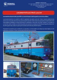
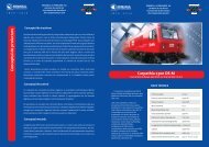
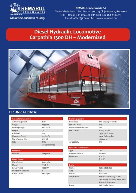
<strong>Diesel</strong> Hydraulic Locomotive<br />
Carpathia 1300 DH – Modernized<br />
TECHNICAL DATA:<br />
11<br />
Final drives<br />
F 35 P<br />
F 35 SP
REMARUL 16 februarie SA<br />
Tudor Vladimirescu Str., No 2-4, 400225 Cluj–Napoca, Romania<br />
Tel: +40 264 435 276, 436 045 Fax: +40 264 432 299<br />
E-mail: office@remarul.eu www.remarul.eu<br />
Driving concept<br />
The power delivered by the new Caterpillar 3508B diesel-engine is transmitted to the TH2 turbo-transmission via a<br />
main connecting shaft. Due to the extra power of the engine, the TH2 was modified and strengthened. The TH2 has<br />
two speed-converters, one <strong>for</strong> starting and one <strong>for</strong> normal service. From there, the power is transmitted to the NG<br />
1200/2 reducer-inverser, which has two working regimes, heavy and easy, depending on the load being hauled. For<br />
shunting operation, the heavy working regime boosts power output in the domain of low-speeds, at the cost of max<br />
speed. However, the easy regime, is used to reach max speed with easy hauls in the main-line operating service. The<br />
power output from the reducer-inverser is transferred to the two bogies using two connecting shafts and from here<br />
it’s distributed to the wheels using the simple F35P and double F35SP final drives. The hydrostatic cooling system is<br />
provided by Behr and uses a high-capacity fan controlled by heat sensors placed in key places, in the engine and<br />
transmission. Also, a smaller fan keeps the temperature inside the engine bay within controlled levels.<br />
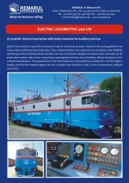
Control concept<br />
Old engine’s control system based on air pressure levels and mechanical regulators was scrapped, and replaced with<br />
an electronic control unit. Also, the old mechanical Knorr D2 automatic train brake regulators and Oerlikon FD1<br />
locomotive brake regulators are now replaced by Knorr Bremse's RHZE3-4 and DBCU1 electronic units. As a result, the<br />
reliability is greatly increased, and the new joystick-type control system signals Knorr Bremse's electronic units the<br />
desired brake inputs. To improve the air compressor's overall per<strong>for</strong>mance, the old 2A320 piston compressor is<br />
replaced by Almig's TA11H screw-type hydrostatic-driven air compressor. Fitted to the air compressor is an<br />
intercooler cools down the air cycled through. The whole control and execution logic is now supplied at 24Vcc in<br />
contrast with the old locomotive which had several supply voltage demands. The modernization process also<br />
eliminated several power-consumers, and replaced the generator-startermotor type Dynastarter with a belt-driven<br />
Niehoff C708 C.E.alternator.<br />
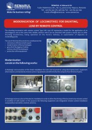
Mechanical concept<br />
The base-frame of the locomotive is repaired, strentgthened and consolidated. Then, the new engine is installed,<br />
alltogheter with capital repaired transmission elements. After this, the improved front-view visibility cab and the<br />
modular hood are to be fitted. The new low-profile hood is made up of four independent modules, the exhaust hood,<br />
the engine hood, the cooling equipment hood and opposite to the cab, the little hood.