MSP Multiple Set Point Switch - Electro-Sensors, Inc.
MSP Multiple Set Point Switch - Electro-Sensors, Inc.
MSP Multiple Set Point Switch - Electro-Sensors, Inc.

You also want an ePaper? Increase the reach of your titles
YUMPU automatically turns print PDFs into web optimized ePapers that Google loves.
<strong>MSP</strong> <strong>Multiple</strong> <strong>Set</strong> <strong>Point</strong> <strong>Switch</strong><br />
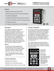
Principle of Operation<br />
The pulser disc (or wrap), that provides 16 magnetic targets of<br />
alternating polarity, is attached to the monitored shaft. As the<br />
magnets on the disc (or wrap) rotate past the sensor, the Hall<br />
Effect device switches high and low to produce a digital signal<br />
with a frequency proportional to shaft speed. The signal is<br />
transmitted to the <strong>MSP</strong>, which converts the digital signal into a<br />
0-10 VDC reference voltage. Prior to operation, the set points<br />
are calibrated to a threshold voltage (between 0 and 10 VDC).<br />
The shaft speed reference voltage is compared to the set point<br />
threshold voltage and the relays are actuated when the set point<br />
threshold is crossed. Relays energize above the set point in underspeed<br />
mode and are de-energized below the set point in overspeed<br />
mode.<br />
ESI Pulser Disc<br />
Pulser Discs can be used with all ESI sensors. To mount the<br />
pulser disc, center drill the monitored shaft to a depth of 1/2”<br />
with a No. 21 drill and tap it for a 10-32UNF screw. Apply<br />
LoctiteTM, or a similar adhesive, on the screw threads to keep<br />
the pulser disc tight. Attach the disc, decal side out, with the 10-<br />
32UNF machine screw provided.<br />
<br />
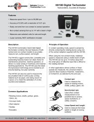
Figure 1: Standard 906 Sensor and Pulser Disc<br />
<br />
Figure 2: Standard 906 Sensor and Pulser Wrap<br />
<br />
<br />
<br />
ESI Pulser Wrap (optional)<br />
Pulser Wraps can be used with all ESI sensors. The pulser wraps<br />
are custom manufactured to fit the specific diameter of the shaft<br />
on which they will be mounted. To mount the wrap, remove the<br />
4 Allen-head cap screws holding the halves of the wrap together,<br />
place the halves around the shaft, and reinsert the screws. Tighten<br />
the screws to 8-ft. lbs.<br />
ESI Transducer Installation<br />
The standard transducer is supplied with a mounting bracket and<br />
two jam nuts. The explosion-proof transducer is supplied with<br />
a slotted mounting bracket. The transducer should be installed<br />
so that the center of the transducer passes through the centerline<br />
of the magnets as they rotate. When using the pulser disc, the<br />
center of the magnetized area of the disc, shown as dimension<br />
“B” in figures 1 and 3, is 1 3/4 inches from the center hole of the<br />
disc. The gap distance between the sensor and the disc or wrap,<br />
Dimension “A” in the diagrams, can be from 1/16” to 3/8”. The<br />
proper gap distance is achieved by adjusting the jam nuts on the<br />
standard transducer and by adjusting the position of the explosion<br />
proof transducer using the slots on the mounting bracket.<br />
Figure 3: Explosion proof Sensor and Pulser Disc<br />
<br />
<br />
Figure 4: Explosion proof Sensor and Pulser Wrap<br />
<br />
6111 Blue Circle Drive<br />
Minnetonka, MN 55343<br />
Phone: 952.930.0100<br />
Fax: 952.930.0130<br />
ISO 9001:2000 Certified<br />
Free Catalog and Application Assistance<br />
1.800.328.6170<br />
Visit Us Online<br />
www.electro-sensors.com<br />
990-002000 Revision A
Input Power<br />
Input power connections are made via terminal strip TB9. Refer<br />
to the table below for the terminal locations.<br />
Terminal 115 VAC 230 VAC<br />
TB9-1 Hot Hot (L1)<br />
TB9-2 Neutral Hot (L2)<br />
TB9-3 Earth Ground Earth Ground<br />
Transducer<br />
Transducer connections are made via terminal strip TB10. Refer<br />
to the table below for terminal designations.<br />
Terminal Description ESI 906 & 907<br />
Other<br />
ESI <strong>Sensors</strong><br />
ESI Prox<br />
TB10-1 Supply Red Red Brown<br />
TB10-2 Signal Black Clear Black<br />
TB10-3 Ground Clear & Shield Black & Shield Blue<br />
Calibration<br />
Note: Factory calibration is recommended to assure highest<br />
possible accuracy. Refer to tables below for all calibration<br />
adjustments. To calibrate the <strong>MSP</strong> accurately, a voltmeter in the<br />
0-10 VDC range must be used. Connect the voltmeter to the 0-10<br />
VDC output terminals observing the proper polarity (TB11-5 is<br />
positive and TB11-6 is negative). With the voltmeter attached,<br />
115 VAC input power applied, and the monitored system off,<br />
place the Range Selector <strong>Switch</strong><br />
(S2) in the position within which the actual operating speed<br />
falls (i.e. 175 RPM would be within the 0-200 range, 500 RPM<br />
would be within the 0-2000 range. See below). Place the OP/SP<br />
Selector <strong>Switch</strong> (S3) in the “0” position. Turn the 0-10 VDC Zero<br />
Adjustment Potentiometer (R47) counterclockwise to decrease or<br />
clockwise to increase until a reading of zero (0 VDC) is attained<br />
on the voltmeter. Next, run the monitored shaft<br />
at maximum operating speed and turn the 0-10 VDC Gain<br />
Potentiometer (R25) clockwise to increase or counterclockwise<br />
to decrease until a reading of 10 VDC is shown on the voltmeter.<br />
Because there is a slight<br />
interaction between the zero and gain adjustments, repeat the<br />
calibration procedure to assure maximum accuracy.<br />
<strong>Set</strong> <strong>Point</strong> Adjustment<br />
Each relay set point on the <strong>MSP</strong> must be individually adjusted<br />
to the desired threshold voltage, which determines the actuation<br />
speed. The threshold voltage represents an exact RPM based on<br />
the original 0-10 VDC calibration. For example, if the maximum<br />
speed of the monitored shaft that was calibrated as 10 VDC were<br />
200 RPM, a threshold voltage of 5 VDC would equal a set point<br />
speed of 100 RPM. See below and the following page for all<br />
terminal and adjustment locations. With the voltmeter attached<br />
to the 0-10 VDC output terminals (TB11-5 = positive, TB11-6<br />
= negative, use the OP/SP Selector <strong>Switch</strong> to select the number<br />
of the set point to be calibrated. The voltmeter will display the<br />
existing threshold voltage. Use the adjustment potentiometer<br />
corresponding to the set point to adjust the threshold voltage to<br />
the level representing the desired set point level (see example<br />
above). The formula for converting the desired set point speed to<br />
threshold voltage is:<br />
Desired <strong>Set</strong> <strong>Point</strong> Speed<br />
Maximum Speed<br />
X 10 = <strong>Set</strong> <strong>Point</strong> Range<br />
Use the Over / Under Speed <strong>Switch</strong> (S1) to select over or under<br />
speed actuation. The number on the switch matches the set-point.<br />
In under speed mode the relay will de-energize when the shaft<br />
speed is below the set point speed. In over speed mode the relay<br />
will de-energize when the shaft speed is above the set point<br />
speed. A green LED will illuminate when the relay is energized.<br />
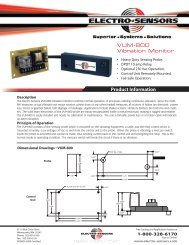
Potentiometer Adjustment<br />
Relay Connections<br />
TB1 - 8 Connection<br />
1 N.C.<br />
2 Com<br />
3 N.O.<br />
Pot<br />
R2<br />
R5<br />
R7<br />
R9<br />
R10<br />
R14<br />
R24<br />
R31<br />
R36<br />
R37<br />
R47<br />
R25<br />
R35<br />
Function<br />
SP1 Adjust<br />
SP2 Adjust<br />
SP3 Adjust<br />
SP4 Adjust<br />
SP5 Adjust<br />
SP6 Adjust<br />
SP7 Adjust<br />
SP8 Adjust<br />
4-20mA Offset Adjust<br />
4-20mA Gain Adjust<br />
0-10Vdc Zero Adjust<br />
0-10Vdc Gain Adjust<br />
Start Delay (Optional)<br />
OP/SP Selector<br />
S3 Position<br />
0 Operate<br />
1-8 SP1 to 8<br />
9 Not Used<br />
Input Power<br />
TB9 Connection<br />
1 Hot<br />
2 Neutral<br />
3 Ground<br />
Sensing Head<br />
TB10 Connection<br />
1 Supply<br />
2 Signal<br />
3 Ground<br />
Output Options<br />
TB11 Connection<br />
1 N/C<br />
2 N/C<br />
3 4-20mA +<br />
4 4-20mA -<br />
5 0-10Vdc +<br />
6 0-10Vdc -<br />
S2 RPM Range Selector<br />
RPM S2 Pos<br />
0-200 A<br />
0-2,000 B<br />
0-20,000 C<br />
<br />
<br />
<br />
<br />
<br />
<br />
<br />
<br />
<br />
<br />
<br />
<br />
<br />
<br />
<br />
<br />
<br />
<br />
<br />
<br />
<br />
<br />
<br />
<br />
<br />
<br />
<br />
<br />
<br />
<br />
<br />
<br />
<br />
<br />
<br />
<br />
<br />
<br />
<br />
<br />
<br />
<br />
<br />
<br />
<br />
<br />
<br />
<br />
<br />
<br />
<br />
<br />
<br />
<br />
<br />
<br />
<br />
<br />
<br />
<br />
<br />
<br />
<br />
<br />
<br />
<br />
<br />
<br />
<br />
<br />
<br />
<br />
2-4<br />
Free Catalog and Application Assistance<br />
1.800.328.6170<br />
Website: www.electro-sensors.com<br />
990-002000 Revision A
(S3 <strong>Switch</strong> setting) Potentiometer to Adjust<br />
0 = Operate<br />
1 = <strong>Set</strong>-<strong>Point</strong> 1 R2<br />
2 = <strong>Set</strong>-<strong>Point</strong> 2 R5<br />
3 = <strong>Set</strong>-<strong>Point</strong> 3 R7<br />
4 = <strong>Set</strong>-<strong>Point</strong> 4 R9<br />
5 = <strong>Set</strong>-<strong>Point</strong> 5 R10<br />
6 = <strong>Set</strong>-<strong>Point</strong> 6 R14<br />
7 = <strong>Set</strong>-<strong>Point</strong> 7 R24<br />
8 = <strong>Set</strong>-<strong>Point</strong> 8 R31<br />
4-20 mA Output (Optional)<br />
This option provides a 4-20 mA current output proportional to<br />
speed for interfacing with a PLC or other device. To calibrate<br />
the output, connect a milliammeter in series with the external<br />
monitoring device. Make sure proper polarity is observed:<br />
TB11-3 is positive, TB11-4 is negative. Apply 115 VAC power<br />
to the <strong>MSP</strong>. With the monitored system off, set the offset level<br />
to a reading of 4 mA by turning the 4-20 mA Offset Adjustment<br />
(R36) — counterclockwise to decrease, clockwise to increase.<br />
To set the gain, run the monitored shaft at full speed. Adjust the<br />
output to a reading of 20 mA using the 4-20 mA Gain Adjustment<br />
(R37) turn clockwise to increase, counterclockwise to decrease.<br />
Note: Because there is interaction between the offset and<br />
gain potentiometers, the process should be repeated to ensure<br />
accuracy.<br />
Digital or Analog Meter (Optional)<br />
Note: When purchasing an analog or digital meter, supplemental<br />
literature with installation instructions will be provided. Use the<br />
following meter calibration instructions instead of the normal<br />
Calibration instructions. The optional meters are used to display<br />
shaft speed. Calibration procedures when using the meters are<br />
different than the normal calibration procedure because the<br />
voltage output is used to generate the desired reading on the<br />
display, not to generate a precise 0-10 VDC output. With the<br />
monitored shaft stopped, adjust the 0-10 VDC Zero Potentiometer<br />
(R47) until zero (0) is displayed on the meter.<br />
Run the monitored shaft at maximum speed - (this speed should<br />
be a known RPM or engineering unit value). Adjust the 0-10<br />
VDC Gain Potentiometer until the display shows the value<br />
desired. When adjusting set points using a properly calibrated<br />
ESI meter, the display will show the set point speed (in RPM or<br />
engineering units) instead of the threshold voltage. Because there<br />
is interaction between the zero and gain potentiometers, repeat<br />
the process for better accuracy. The analog meter does not require<br />
115 VAC power. It is 50-graduation taut band meter movement<br />
scaled to customer specifications. After attaching the 0-10 VDC<br />
output (TB11-5 to meter positive, TB11-6 to meter negative);<br />
follow the digital “meter calibration instructions above.<br />
WARNING!<br />
During a stopped condition, even a slight movement of the shaft or<br />
magnetic disc could energize the control relay and start the motor<br />
if the Motor Starter Auxiliary Normally Open Contact (MS Aux N.O.)<br />
is not wired in series as shown In these typical wiring diagrams.<br />
This situation could cause equipment damage or PERSONAL<br />
INJURY! To prevent starting the motor accidentally,<br />
ALWAYS USE PROPER LOCKOUT — TAG-OUT PROCEDURES.<br />
Wiring Diagram Key<br />
MS Motor Starter (not supplied)<br />
OL Overload Contacts<br />
N. O. Normally open (relay is in a de-energized state)<br />
TDR Time Delay “OFF” Relay (not supplied)<br />
If the shaft being monitored comes up to speed slowly, a TDR can be<br />
use so the operator will not have to hold the START button in.<br />
Troubleshooting guide<br />
Problem Troubleshooting step / Solution<br />
Unit dead Check for blown fuse / replace if bad<br />
Unstable output Check the sensor / adjust sensor gap and<br />
alignment as necessary<br />
No Output<br />
Unable to<br />
calibrate unit<br />
Check the sensor / adjust sensor gap and<br />
alignment as necessary<br />
Check for sensor signal at board / replace<br />
sensor if the gap and alignment are good<br />
and board has a good sensor supply and<br />
unit works with a generator.<br />
Check for sensor signal at board / replace<br />
unit if the input to the <strong>MSP</strong> has a good<br />
sensor supply of 15 Vdc and signal is<br />
present, 15 Vdc squarewave, but there is<br />
no analog or relay activity.<br />
Verify Unit is set to correct range / <strong>Set</strong> if<br />
necessary<br />
3-4<br />
Free Catalog and Application Assistance<br />
1.800.328.6170<br />
Website: www.electro-sensors.com<br />
990-002000 Revision A
<strong>MSP</strong> Series General Specifications<br />
Input Voltage<br />
Power<br />
Frequency<br />
Wattage<br />
Fuse<br />
Input Signal<br />
Type<br />
Amplitude<br />
Impedance<br />
Frequency<br />
Output Signal<br />
Type<br />
Additional Output<br />
Accuracy<br />
Calibration<br />
Parameters<br />
• 115 Vac ±10% Standard<br />
• 230 Vac ±10%<br />
50-60Hz Optional<br />
12A<br />
1/8 Amp Slo-Blo, 115 Vac<br />
1/16 Amp Slo-Blo, 230 Vac<br />
Parameters<br />
Open Collector/Logic<br />
15 Vdc nom., 8 V min.<br />
2200 Ohms to 15 VDC<br />
3.33 Hz min, 2.66 KHz max.<br />
Parameters<br />
0-10 VDC Standard (calibration)<br />
4-20 mA Optional<br />
± 0.5% @ Midrange<br />
Selection of 3 ranges:<br />
0-200 RPM<br />
0-2,000 RPM<br />
0-20,000 RPM<br />
0-10 Calibration Voltage 22 Turn Zero and Gain adjustment<br />
potentiometers<br />
<strong>Set</strong> <strong>Point</strong> Data<br />
Number Available<br />
Adjustments<br />
Hysteresis<br />
Range<br />
Mode<br />
Response Time<br />
Relay Output<br />
Contact Configuration<br />
Rating<br />
Energized Indication<br />
Physical/Environment<br />
Mounting<br />
Operating Temperature<br />
Storage Temperature<br />
Electrical Connections<br />
Pulser Disc<br />
Material<br />
Dimensions<br />
Operating Temperature<br />
Maximum Speed<br />
Parameters<br />
3 Min, 8 Max<br />
22 Turn Potentiometers<br />
0.1% of Full Scale<br />
0% to 100% Full Scale<br />
Selectable: Over or Under Speed<br />
0-200 RPM 1.5 seconds<br />
0-2,000 RPM 0.5 seconds<br />
0-20,000 RPM 0.5 seconds<br />
Parameters<br />
1 Form C (SPDT) Per Relay<br />
5 amp @ 28 Vdc or 115 Vac Resistive<br />
Green LED<br />
Parameters<br />
Chassis (See Drawing)<br />
0ºC to +70ºC<br />
-40ºC to +85ºC<br />
Terminal Strip<br />
Parameters<br />
Nylon 12 Std, Aluminum Opt.<br />
4-inch diameter x 1/4-inch thick<br />
0ºC to +60ºC*<br />
Consult factory<br />
Signal Cable<br />
Operating Temperature<br />
Air Gap<br />
Explosionproof Sensor<br />
Housing and Cover<br />
4-conductor shielded, 10 feet length<br />
0ºC to + 75ºC*<br />
1/16 inch to 1/4 inch<br />
Parameters<br />
Cast aluminum, C.S.A. and FM, Approved<br />
UL, Rated Class I Group C, D; Class II<br />
Group E, F, G; Class III<br />
Specifications are subject to change without notice.<br />
<br />
<br />
<br />
<br />
<br />
<br />
<br />
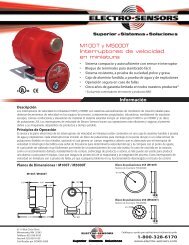
Dimensional Drawings<br />
<br />
<br />
<br />
Standard 906 Sensor<br />
<br />
<br />
<br />
<br />
<br />
<br />
<br />
<br />
<br />
<br />
Standard XP Sensor<br />
<br />
<br />
<br />
<br />
<br />
<br />
XP Sensor Bracket<br />
<br />
<br />
<br />
<br />
<br />
<br />
<br />
<br />
Pulser Wrap (Optional)<br />
Material<br />
Operating Temperature<br />
Maximum Speed<br />
Standard Sensor (906)<br />
Material Sensor Body<br />
Material Mount Bracket<br />
Output Types<br />
Parameters<br />
Consult factory or our web site<br />
-40ºC to +60ºC<br />
Consult factory or our web site<br />
Parameters<br />
Aluminum 3/4 - 16 UNF thread<br />
Plate steel<br />
Quadrature, NPN open collector<br />
current sinking 20 mA max<br />
4-4<br />
Free Catalog and Application Assistance<br />
1.800.328.6170<br />
Website: www.electro-sensors.com<br />
990-002000 Revision A