EZ-100 Rev B - Electro-Sensors, Inc.
EZ-100 Rev B - Electro-Sensors, Inc.
EZ-100 Rev B - Electro-Sensors, Inc.

You also want an ePaper? Increase the reach of your titles
YUMPU automatically turns print PDFs into web optimized ePapers that Google loves.
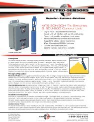
600 Series Proximity Switches<br />
IMPROVED - Broader gap distances<br />
• Non-contact sensing<br />
• Solid-state - no moving parts<br />
• Durable corrosion resistant metal housings<br />
• High speed repeatability<br />
• Short-circuit and reverse polarity protection<br />
• Outputs CMOS compatible<br />
• Full output signal down to zero Hz<br />
• LED operation indicator on all models<br />
Product Information<br />
Description<br />
<strong>Electro</strong>-<strong>Sensors</strong>’ Model 600 Series Proximity Switches are active digital sensing devices that generate one pulse per pass of<br />
an actuating target within their sensing field. No direct contact with target material is necessary. Each sensor is entirely<br />
solid state with no moving parts to wear out. This provides for long life with little or no maintenance. The wide range of<br />
supply voltages to the 600 Series permits them to be directly interfaced with low voltage solid state controls, such as<br />
programmable controllers and electromechanical relay loads. All sensors are polyurethane or epoxy encapsulated and are<br />
provided complete with mounting bracket, jam nuts, and 6 feet of cable.<br />
Principle of Operation<br />
The Model 600 Series Proximity Switches utilize an oscillator circuit to generate a high frequency field that is radiated from<br />
a coil in the tip of the sensor. When a metal object or “target” enters this high frequency field, eddy currents are induced<br />
into the target. A detection circuit immediately senses a loss of energy in the oscillator circuit. This low amplitude condition<br />
causes the solid state output from the sensor to switch. When the “target” material moves away from the sensing face of<br />
the switch, the oscillator regenerates and the switch returns to its normal state. <strong>Electro</strong>-<strong>Sensors</strong>’ products bring efficiency<br />
and safety to your operations by preventing machine damage, product waste, and costly downtime.<br />
Typical Applications<br />
600 Series Proximity Switches can be used in the following applications:<br />
• Detect conductive materials<br />
• Sequencing automated equipment<br />
• Motion detection (keyways, bolt-heads, gears, etc.) • Interlocking machine process control<br />
• Parts detection and counting<br />
• Drive motor stall detection<br />
• Tool detection (broken or damaged)<br />
• Input to programmable controllers<br />
• Indexing control<br />
Sensing Gear Teeth<br />
Sensing Boltheads or Screws<br />
Sensing Keyslots<br />
Sensing Keystock<br />
6111 Blue Circle Drive<br />
Minnetonka, MN 55343<br />
Phone: 952-930-0<strong>100</strong><br />
Fax: 952-930-0130<br />
ISO 9001:2000 Certified<br />
Superior · Systems · Solutions<br />
Free Catalog and Application Assistance<br />
1-800-328-6170<br />
Visit us online<br />
www.electro-sensors.com
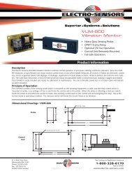
Sensor Selection<br />
The 600 Series offers two types of Proximity Switch <strong>Sensors</strong>:<br />
shielded and unshielded. For general purpose applications<br />
unshielded sensors are usually preferable to shielded because<br />
they have greater sensing range capabilities. Shielded sensors,<br />
however, have the distinct advantages of being capable of<br />
flush mounting directly into a metal surface. This permits<br />
minimum spacing between sensors, and conductive materials<br />
not directly in line with the sensor’s face will not affect<br />
operation. See Figures 1 and 2.<br />
600 Series Proximity Switches<br />
Installation<br />
The switch should be mounted as close as possible to the<br />
target material for best performance. Care should be taken to<br />
mount the sensor firmly in such a position as to give the<br />
sensing face the best possible view of the target material, free<br />
from conductive obstructions. The target material likewise<br />
should present as much surface area as possible to the sensor<br />
face. It is recommended that proximity switches be mounted<br />
with a vertical sensing face or looking down when possible.<br />
Metal filings or chips will not normally affect proximity<br />
sensors, but careful placement of sensors provides the most<br />
accurate results possible.<br />
Unshielded Types<br />
Require metal-free area<br />
Figure 1<br />
Shielded Types<br />
Flush-mount condition<br />
Figure 2<br />
Wiring Diagram<br />
All Models Normally Open<br />
1.5 X D<br />
Sensing<br />
Field<br />
Sensing<br />
Field<br />
Metal<br />
Metal<br />
Note: When this sensor is used as a stand alone pulse<br />
generator, an external pull up resistor(*) must be<br />
applied across the output as shown. .<br />
Recommended Values: 2.2K Ohms or 3.3K Ohms<br />
External resistors are not required when sensor is used<br />
with standard <strong>Electro</strong>-Sensor products.<br />
How to Order A Proximity Switch<br />
1. Determine the sensing rang<br />
ange required for your application. Keep in mind that the sensing ranges in the specification table<br />
are for standard targets of ferrous metal. Non-ferrous targets will reduce sensing distance.<br />
2. Will an unshielded sensor work, or does your application require a shielded sensor because of metal objects close by<br />
or other proximity switches?<br />
3. At what speed does the switch have to operate? The specification table provides this information as maximum switching<br />
Hz, or switching cycles per second.<br />
4. Still have questions? Call <strong>Electro</strong>-<strong>Sensors</strong> toll-free at 1-800-328-6170.<br />
Specifications • 600 Series Proximity Switch<br />
Unshielded <strong>Sensors</strong> (Extended Range)<br />
BODY SIZE SENSING MAX. BODY<br />
BODY<br />
MODEL<br />
DIAMETER RANGE SWITCHING THREAD LENGTH<br />
NO.<br />
(MM INCHES) INCHES Hz<br />
SIZE (MM INCHES)<br />
608 8 0.314 0.080 800 M8 x 1 30 1.18<br />
612 12 0.472 0.200 400 M12 x 1 35 1.38<br />
618 18 0.708 0.390 200 M18 x 1 40 1.57<br />
630 30 1.18 0.710 <strong>100</strong> M30 x 1.5 50 1.97<br />
Shielded <strong>Sensors</strong> (Suitable for Flush Mounting)<br />
608-1 8 0.314 0.060 2,000 M8 x 1 30 1.18<br />
612-1 12 0.472 0.080 1,500 M12 x 1 35 1.38<br />
618-1 18 0.708 0.200 600 M18 x 1 40 1.57<br />
630-1 30 1.18 0.390 400 M30 x 1.5 50 1.97<br />
All outputs: Open collector current sinking (NPN) normally open<br />
Addit<br />
dditional ional Specific<br />
icat<br />
ations<br />
Switching capability .................. ±10% of rated sensing range<br />
Hysteresis ....................................... 15% max.<br />
Input voltage range .................... 10-30 Vdc<br />
Ripple of DC supply ................... 10% max.<br />
Maximum load ............................. 200 mA<br />
Current consumption ................. 17 mA max.<br />
Voltage drop ................................. 2 Vdc (switch actuated)<br />
No load current............................ 3 mA<br />
Maximum duty cycle ................ <strong>100</strong>%<br />
Operating temperature ............. -25 o C to +70 o C<br />
Mounting ........................................ Jam nuts and a bracket<br />
Cable length .................................. 6.5' of 3-conductor<br />
Housing material ......................... Nickel plated brass<br />
Protection ....................................... Short circuit & reverse polarity<br />
NEMA ratings ................................. 1, 3, 4, 6, 12 & 13<br />
6111 Blue Circle Drive<br />
Minnetonka, MN 55343<br />
Phone: 952-930-0<strong>100</strong><br />
Fax: 952-930-0130<br />
ISO 9001:2000 Certified<br />
Specifications subject to change without notice.<br />
Superior · Systems · Solutions<br />
ES-600 <strong>Rev</strong>. E<br />
Free Catalog and Application Assistance<br />
1-800-328-6170<br />
Visit us online<br />
www.electro-sensors.com