(LTE) Attach and Default Bearer Setup - EventHelix.com
(LTE) Attach and Default Bearer Setup - EventHelix.com
(LTE) Attach and Default Bearer Setup - EventHelix.com

Create successful ePaper yourself
Turn your PDF publications into a flip-book with our unique Google optimized e-Paper software.
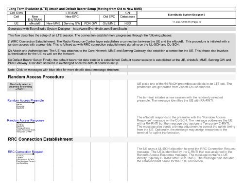
Long Term Evolution (<strong>LTE</strong>) <strong>Attach</strong> <strong>and</strong> <strong>Default</strong> <strong>Bearer</strong> <strong>Setup</strong> (Moving from Old to New MME)<br />
Cell Sites <strong>LTE</strong>/SAE CN<br />
Cell New<br />
New EPC Old EPC Databases<br />
E-UTRAN<br />
UE eNodeB New MME Serving GW PDN GW Old MME HSS<br />
Generated with EventStudio System Designer - http://www.<strong>EventHelix</strong>.<strong>com</strong>/EventStudio<br />
EventStudio System Designer 5<br />
11-Dec-12 07:45 (Page 1)<br />
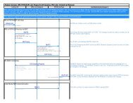
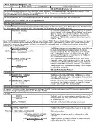
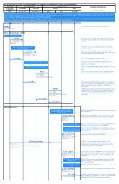
This flow describes the setup of an <strong>LTE</strong> session. The connection establishment progresses through the following phases:<br />
(1)RRC Connection Establishment: The Radio Resource Control layer establishes a connection between the UE <strong>and</strong> the eNodeB. This procedure is initiated with a<br />
r<strong>and</strong>om access with a preamble. This is follwed up with RRC connection establishment signaling on the UL-SCH <strong>and</strong> DL-SCH.<br />
(2) <strong>Attach</strong> <strong>and</strong> Authentication: The UE now attaches to the Core Network. MME <strong>and</strong> Serving Gateway also establish a context for the UE. This phase also involves<br />
authentication for the UE as well are the Network.<br />
(3) <strong>Default</strong> <strong>Bearer</strong> <strong>Setup</strong>: Finally, the default bearer for data transfer is established. <strong>Default</strong> bearer session is established at the UE, eNodeB, MME, Serving GW <strong>and</strong><br />
PDN Gateway. User data sessions is exchanged once the default bearer is setup.<br />
Note: Click on messages with blue titles for more details about message structure.<br />
R<strong>and</strong>om Access Procedure<br />
R<strong>and</strong>omly select a<br />
preamble for sending<br />
a RACH<br />
UE picks one of the 64 RACH preambles available in an <strong>LTE</strong> cell. The<br />
preambles are generated from Zadoff-Chu sequences.<br />
R<strong>and</strong>om Access Preamble<br />
RACH,<br />
Preamble,<br />
RA-RNTI<br />
The terminal initiates a new session with the r<strong>and</strong>omly selected<br />
preamble. The message identifies the UE with RA-RNTI.<br />
R<strong>and</strong>om Access Response<br />
DL-SCH,<br />
RA-RNTI,<br />
Timing Advance,<br />
Uplink Resource Grant,<br />
Temporary C-RNTI<br />
RRC Connection Establishment<br />
The eNodeB responds to the preamble with the "R<strong>and</strong>om Access<br />
Response" message on the DL-SCH. The message addresses the UE<br />
with a RA-RNTI but the message also assigns a Temporary C-RNTI.<br />
The message also sends a timing adjustment to correct the uplink timing<br />
from the UE. Optionally, the message may assign resources to the<br />
terminal for uplink transmission.<br />
RRC Connection Request<br />
UL-SCH,<br />
C-RNTI,<br />
UE-Identity = S-TMSI,<br />
Establishment Cause =<br />
mo-Signalling<br />
The UE uses a UL-SCH allocation to send the RRC Connection Request<br />
message. The UE is identified by the C-RNTI that was assigned in the<br />
R<strong>and</strong>om Access Response message. The message contains a UE<br />
identity (typically S-TMSI: MMEC+M-TMSI). The message also includes<br />
the establishment cause for the RRC connection.
Long Term Evolution (<strong>LTE</strong>) <strong>Attach</strong> <strong>and</strong> <strong>Default</strong> <strong>Bearer</strong> <strong>Setup</strong> (Moving from Old to New MME)<br />
Cell Sites <strong>LTE</strong>/SAE CN<br />
Cell New<br />
New EPC Old EPC Databases<br />
E-UTRAN<br />
UE eNodeB New MME Serving GW PDN GW Old MME HSS<br />
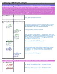
RRC Connection <strong>Setup</strong><br />
DL-SCH,<br />
C-RNTI,<br />
SRB Identity,<br />
DL AM RLC,<br />
UL AM RLC,<br />
UL-SCH Config,<br />
PHR Config,<br />
Uplink Power Control<br />
<strong>Attach</strong> <strong>and</strong> Authentication<br />
EventStudio System Designer 5<br />
11-Dec-12 07:45 (Page 2)<br />
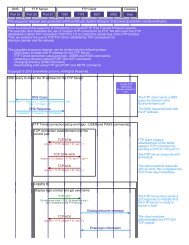
eNodeB responds with an RRC Connection <strong>Setup</strong> message on the<br />
DL-SCH. The message creates the signaling radio bearer (SRB) in<br />
Acknowledged mode. The message also contains configuration<br />
parameters for uplink RLC, UL-SCH, Power Head Room (PHR) <strong>and</strong><br />
Uplink Power Control.<br />
RRC Connection <strong>Setup</strong> Complete + NAS <strong>Attach</strong> Request<br />
UL-SCH,<br />
Selected PLMN Identity,<br />
Old TAI,<br />
Old GUMMEI,<br />
Old GUTI,<br />
Selected PLMN Identity<br />
Identify the MME from the Old<br />
GUMMEI<br />
The UE signals the setup of the RRC connection. The message is also<br />
used to initiate the <strong>Attach</strong> procedure by sending the <strong>Attach</strong> Request as<br />
NAS Payload. The attach message contains the old GUTI (Globally<br />
Unique Temporary Identifier).<br />
Identify the MME from the Old GUMMEI (Globally Unique MME<br />
Identifier) reported by the UE.<br />
S1AP Initial UE Message [<strong>Attach</strong> Request + PDN Connectivity Request]<br />
id = eNB UE S1AP ID,<br />
Tracking Area Id = TAI+Cell Id,<br />
EPS <strong>Attach</strong> Type = EPS <strong>Attach</strong>,<br />
Identity = Old GUTI,<br />
EPS Encryption <strong>and</strong> Integrity<br />
Algorithms,<br />
Selected Network<br />
The <strong>Attach</strong> message is sent in the Initial UE message to the MME over<br />
the S1AP interface. The "<strong>Attach</strong> Request" is embedded in the Initial UE<br />
Message. The message also includes the PDN Connectivity Request<br />
message. The Tracking Area Identify (TAI) <strong>and</strong> E-UTRAN Cell Global<br />
Identifier (ECGI) are also included. Note that the eNodeB uses the<br />
eNB-UE-S1APID to uniquely identify the UE.<br />
Identification Request [<strong>Attach</strong> Request]<br />
Old GUTI<br />
Identification Response<br />
Since the UE identified itself with GUTI <strong>and</strong> the MME has changed since<br />
detach, the new MME uses the GUTI received from the UE to derive the<br />
old MME, <strong>and</strong> send an Identification Request (old GUTI, <strong>com</strong>plete <strong>Attach</strong><br />
Request message) to the old MME to request the IMSI.<br />
The old MME responds with Identification Response (IMSI, unused EPS<br />
Authentication Vectors, KSIASME, KASME)<br />
Authentication Info Request<br />
Authentication Info Answer
Long Term Evolution (<strong>LTE</strong>) <strong>Attach</strong> <strong>and</strong> <strong>Default</strong> <strong>Bearer</strong> <strong>Setup</strong> (Moving from Old to New MME)<br />
Cell Sites <strong>LTE</strong>/SAE CN<br />
Cell New<br />
New EPC Old EPC Databases<br />
E-UTRAN<br />
UE eNodeB New MME Serving GW PDN GW Old MME HSS<br />
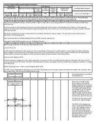
Ciphered Options Request<br />
EventStudio System Designer 5<br />
11-Dec-12 07:45 (Page 3)<br />
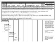
Since the UE has set the Ciphered Options Transfer Flag in the <strong>Attach</strong><br />
Request message, the ciphered Options i.e. PCO or APN or both, shall<br />
now be retrieved from the UE.<br />
Ciphered Options Response<br />
Origin,<br />
Destination,<br />
User Name = IMSI,<br />
Visited PLMN Id<br />
Update Location Request<br />
Since the MME has changed since the last detach, the MME sends an<br />
Update Location Request message to the HSS. The MME capabilities<br />
indicate the MME's support for regional access restrictions functionality.<br />
Update Type indicates this is <strong>Attach</strong> procedure.<br />
Cancel Location<br />
IMSI,<br />
Cancellation Type<br />
The HSS sends Cancel Location to the old MME. The old MME<br />
acknowledges with Cancel Location Ack <strong>and</strong> removes the MM <strong>and</strong><br />
bearer contexts.<br />
Cancel Location Ack<br />
IMSI<br />
<strong>Default</strong> Radio <strong>Bearer</strong> <strong>Setup</strong><br />
Update Location Request Answer<br />
IMSI,<br />
Aggregate MBR (DL <strong>and</strong> UL),<br />
MSISDN,<br />
APN = PDN GW Address, QCI, Charging, Aggregate MBR (DL, UL)<br />
GTP Create Session Request<br />
Sender F-TEID for Control Plane,<br />
ARP,<br />
QCI,<br />
MSISDN,<br />
TAI,<br />
PGW IP Address,<br />
PDN IP Address,<br />
APN,<br />
IP Address Assigned to UE<br />
The HSS acknowledges the Update Location message by sending an<br />
Update Location Answer message to the new MME. The Subscription<br />
Data contains PDN subscription contexts. Each PDN subscription<br />
context contains an 'EPS subscribed QoS profile' <strong>and</strong> the subscribed<br />
APN-AMBR . The new MME validates the UE's presence in the (new)<br />
TA. If all checks are successful then the new MME constructs a context<br />
for the UE.<br />
MME initiates the default route establishment by asking the SGW to<br />
create a GTP tunnel. The APN specified by the UE is used for default<br />
bearer activation. The IP Address assigned to the UE is also included<br />
along with the downlink <strong>and</strong> uplink maximum data rates allowed at the<br />
APN level.<br />
Create a new entry in EPS<br />
<strong>Bearer</strong> table
Long Term Evolution (<strong>LTE</strong>) <strong>Attach</strong> <strong>and</strong> <strong>Default</strong> <strong>Bearer</strong> <strong>Setup</strong> (Moving from Old to New MME)<br />
Cell Sites <strong>LTE</strong>/SAE CN<br />
Cell New<br />
New EPC Old EPC Databases<br />
E-UTRAN<br />
UE eNodeB New MME Serving GW PDN GW Old MME HSS<br />
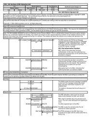
Map from APN to PDN<br />
Gateway<br />
EventStudio System Designer 5<br />
11-Dec-12 07:45 (Page 4)<br />
Buffer<br />
downlink<br />
packets<br />
Create <strong>Default</strong> <strong>Bearer</strong> Request<br />
IMSI,<br />
MSISDN,<br />
APN,<br />
Serving GW Address<br />
Create a new<br />
entry in its EPS<br />
bearer context<br />
table <strong>and</strong><br />
generates a<br />
Charging Id<br />
Serving Gateway sends Create <strong>Default</strong> <strong>Bearer</strong> Request message to the<br />
PDN GW.<br />
The new entry allows the P GW to route user plane PDUs between the S<br />
GW <strong>and</strong> the packet data network, <strong>and</strong> to start charging.<br />
Create <strong>Default</strong> <strong>Bearer</strong> Request<br />
PDN GW User Plane<br />
address,<br />
PDN GW TEIDs User <strong>and</strong><br />
Control Plane,<br />
EPS <strong>Bearer</strong> Identity <strong>and</strong><br />
QoS<br />
Downlink Data<br />
Serving Gateway receives the first downlink data block. This block is<br />
buffered at the Serving GW".<br />
Create <strong>Default</strong> <strong>Bearer</strong> Request<br />
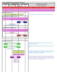
Initial Context <strong>Setup</strong> Request [<strong>Attach</strong> Accept, Activate <strong>Default</strong> <strong>Bearer</strong> Request]<br />
Extract <strong>and</strong> process Initial<br />
Context <strong>Setup</strong> Request<br />
Extract <strong>and</strong> process <strong>Attach</strong><br />
Accept<br />
MME responds back to the eNodeB with a message containing three<br />
messages: SIAP Initial Context <strong>Setup</strong> Request, NAS <strong>Attach</strong> Accept <strong>and</strong><br />
Activate <strong>Default</strong> <strong>Bearer</strong> Request.<br />
The message is identified by the S1AP id that was sent in the initial UE<br />
message. The message contains maximum bit rate information for the<br />
UE. Quality of service information for the new eRAB is also specified<br />
(QCI, maximum bit rate downlink <strong>and</strong> uplink). The information received<br />
in this message will be used to setup radio resources for the eNodeB.<br />
The message is extracted from the NAS payload of the Initial Context<br />
<strong>Setup</strong> Request message. It signals the successful <strong>com</strong>pletion of attach.<br />
The message contains the GUTI <strong>and</strong> the TAI list. This message will be<br />
sent to the NAS layer on the UE.
Long Term Evolution (<strong>LTE</strong>) <strong>Attach</strong> <strong>and</strong> <strong>Default</strong> <strong>Bearer</strong> <strong>Setup</strong> (Moving from Old to New MME)<br />
Cell Sites <strong>LTE</strong>/SAE CN<br />
Cell New<br />
New EPC Old EPC Databases<br />
E-UTRAN<br />
UE eNodeB New MME Serving GW PDN GW Old MME HSS<br />
EventStudio System Designer 5<br />
11-Dec-12 07:45 (Page 5)<br />
Buffer<br />
downlink<br />
packets<br />
Extract <strong>and</strong> process Activate<br />
<strong>Default</strong> <strong>Bearer</strong> Request<br />
RRC Connection Reconfiguration [<strong>Attach</strong> Accept]<br />
EPS Radio <strong>Bearer</strong> Identity,<br />
RLC Mode,<br />
PDCP Sequence Number<br />
The message is extracted from the NAS payload of the Initial Context<br />
<strong>Setup</strong> Request message. The message contains quality of service<br />
information for the default RAB. The Access Point Name (APN) <strong>and</strong><br />
PDN Address are also included. This message will be sent to the NAS<br />
layer on the UE.<br />
The RRC Connection Reconfiguration message is sent to activate the<br />
default radio bearer. The message also carries the <strong>Attach</strong> Accept<br />
message as NAS Payload.<br />
Activate the default<br />
bearer<br />
RRC Connection Reconfiguration Complete<br />
Initial Context <strong>Setup</strong> Response<br />
Direct Transfer [<strong>Attach</strong> Complete]<br />
UE replies back to the eNodeB.<br />
The eNodeB sends the Initial Context Response message to the new<br />
MME. This Initial Context Response message includes the TEID of the<br />
eNodeB <strong>and</strong> the address of the eNodeB used for downlink traffic on the<br />
S1_U reference point.<br />
The UE sends a Direct Transfer message to the eNodeB, which includes<br />
the <strong>Attach</strong> Complete (EPS <strong>Bearer</strong> Identity, NAS sequence number,<br />
NAS-MAC) message.<br />
<strong>Attach</strong> Complete<br />
Uplink Data<br />
Update <strong>Bearer</strong> Request<br />
EPS <strong>Bearer</strong> Identity,<br />
eNodeB address,<br />
eNodeB TEID<br />
Upon reception of both, the Initial Context Response message <strong>and</strong> the<br />
<strong>Attach</strong> Complete message, the new MME sends an Update <strong>Bearer</strong><br />
Request message to the Serving GW.
Long Term Evolution (<strong>LTE</strong>) <strong>Attach</strong> <strong>and</strong> <strong>Default</strong> <strong>Bearer</strong> <strong>Setup</strong> (Moving from Old to New MME)<br />
Cell Sites <strong>LTE</strong>/SAE CN<br />
Cell New<br />
New EPC Old EPC Databases<br />
E-UTRAN<br />
UE eNodeB New MME Serving GW PDN GW Old MME HSS<br />
EventStudio System Designer 5<br />
11-Dec-12 07:45 (Page 6)<br />
Buffer<br />
downlink<br />
packets<br />
Packet buffering is ended.<br />
Update <strong>Bearer</strong> Response<br />
EPS <strong>Bearer</strong> Identity<br />
The Serving GW acknowledges by sending Update <strong>Bearer</strong> Response<br />
message to the new MME. The Serving GW can then send its buffered<br />
downlink packets.<br />
Downlink data<br />
Buffered downlink data is forwarded to the UE.<br />
Generated with EventStudio System Designer - http://www.<strong>EventHelix</strong>.<strong>com</strong>/EventStudio