GL1200 Hondaline CB System Installation Manual - Goldwing Chrome
GL1200 Hondaline CB System Installation Manual - Goldwing Chrome
GL1200 Hondaline CB System Installation Manual - Goldwing Chrome

You also want an ePaper? Increase the reach of your titles
YUMPU automatically turns print PDFs into web optimized ePapers that Google loves.
hondaline<br />
<strong>CB</strong> TRANSCEIVER KIT FOR <strong>GL1200</strong><br />
<strong>Installation</strong> <strong>Manual</strong><br />
The hondaline<br />
Type III Radio & Cassette Deck has all of the advantages<br />
without compromises.<br />
Now available is a <strong>CB</strong> Radio for use with the Type III unit.<br />
To use the <strong>CB</strong> Radio, it is necessary to purchase the<br />
extension kit.<br />
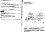
NOTE: This fairing is designed for use only on the<br />
<strong>GL1200</strong>A motorcycle
Index No. Part Name Q’ty<br />
61 <strong>CB</strong> Transceiver assy. 1<br />
62 Component, terminal 1<br />
63 Distributor, ant. 1<br />
64 Cover assy. 1<br />
65 Transceiver harness 1<br />
66 Stay assy., auto vol. 1<br />
67 Nut, hex., 5 mm 1<br />
68 Screw, tapping 3x54 mm 1<br />
69 Nut, hex., cap 5 mm 4<br />
70 <strong>CB</strong> handlebar switch 1<br />
72 Washer, number brkt. Set 4<br />
73 Cap, socket bolt 5 mm 4<br />
74 OW. <strong>CB</strong>, passenger 1<br />
75 <strong>Installation</strong> DWG 1<br />
76 Owner’s Instl. 1<br />
77 Collar, radio SW. 1<br />
PRECAUTIONS<br />
The descriptions are based on the motorcycle already equipped with the Type III radio. And references are to be<br />
made to the instructions furnished with the radio.
INSTALLATION<br />
1) Remove the right and left side covers.<br />
Disconnect the battery negative cable from the battery negative terminal.<br />
2) Remove the left fairing pocket.<br />
3) Remove the Auto volume control unit.<br />
-1 Remove the <strong>CB</strong> blind cover from the fairing by removing the four 5 x 22 mm socket head bolts. (Fig. 2)<br />
Disconnect the three wire connectors of the auto volume unit. (Fig. 3)<br />
-2 Remove the two 4 x 12mm tapping screws and remove the knob and nut from the auto volume control unit.<br />
(Fig. 1)<br />
-3 Remove the bracket form the auto volume control unit.<br />
NOTE: Discard the <strong>CB</strong> blind cover, 4 x 22mm tapping screws, and bracket.<br />
4) Remove the seat.
5) Remove the shelter.<br />
NOTE: To remove the front of the shelter, it is necessary to remove the inner cover by lifting the rear of the<br />
cover.<br />
6) Remove the two tapping screws attaching the left coupler cover and move the holder towards the center.<br />
7) Remove the main amplifier.<br />
-1 Disconnect the main amplifier 2-P black connector.<br />
-2 Straighten the four wire clamps at the main amplifier to release the harnesses.<br />
-3 Remove the two nuts and washers holding the main amplifier; pull the amplifier out between the left fairing<br />
pocket and handlebar by pulling up on the bottom.
8) Connect the two DIN connectors if the transceiver harness (65) to the terminal component (62) color-to-color<br />
(Fig. 7).<br />
9) Remove the seals from the terminal component mounts inside the fairing. Position the terminal component (62)<br />
on the mounts and install using cap nuts (69) and washers (72).<br />
NOTE: Use care when installing the terminal component (62) not to push in the audio harness, <strong>CB</strong> harness<br />
and terminal component harness into the fairing pocket.
10) Reinstall the main amplifier.<br />
11) Connect the terminal component (62) and main amplifier as follows:<br />
-1 Connect the red banded DIN connector from the bottom of the terminal component (62) to the red banded<br />
DIN connector from the bottom of the main amplifier.<br />
12) Return the antenna feeder back into the fairing.
13) Install auto volume control unit and junction box (81) on the transceiver (61).<br />
-1 Position the bracket (66) on the auto volume control unit and install using the 5mm flange nut. Do not over<br />
tighten at this time.<br />
-2 Position the auto volume control unit on the transceiver (61) and install using the 5mm nuts (67). Tighten<br />
the nuts securely. Discard the bracket (88) and 4 x 16mm bolts (82).<br />
14) Install the antenna distributor (63)<br />
-1 Remove the left under cowling (Fig. 13)<br />
-2 Install the distributor (63) using the 5mm cap nuts (69) and washers (72).<br />
-3 Reinstall the left under cowling.
15) Connect the wire harnesses and cables as shown in Fig. 15.<br />
-1 Remove the grommet from the upper hole of the coupler holder.<br />
Route the terminal component (62) harness wires (A) and (B) and antenna distributor wire (C) through<br />
the upper hole into the fairing.<br />
Pry the wires into the small hole, and then reinstall the grommet.<br />
-2 Connect the brown and red 4-P couplers (D) and (E).<br />
-3 Connect the white banded connector (E) to the black/white banded connector (F) before installing the auto<br />
volume control unit, transceiver, and junction box.<br />
-4 Position the auto volume control unit, transceiver and junction box in place and connect the DIN and<br />
antenna connectors. (Din: four places; Antenna: two places)<br />
-5 Install the auto volume control unit, transceiver, and junction box using the 5 x 22mm socket head bolts.
16) Arrange and clamp the wire harnesses and cables as follows:<br />
-1 Arrange the two wires whose DIN connectors were connected to the terminal component (62) and two<br />
antenna feeder wires on top of the main amplifier and secure with the wire clamp.<br />
-2 Store the remaining harnesses and cables under the amplifier and secure with bottom clamps.<br />
NOTE: The left pocket may not be installed if the harnesses and cables are not stored properly.<br />
17) Install the <strong>CB</strong> switch.<br />
-1 Remove the 3 x 34mm tapping screw attaching the radio switch. Referring to Fig. 16, install the <strong>CB</strong><br />
HANDLEBAR switch (70) and spacer (77) with the 3 x 54mm tapping screw (68).<br />
NOTE: Discard the 3 x 34mm tapping screws.<br />
-2 Route the switch wires as shown in Fig. 16 and 17.<br />
NOTE: After attaching the wires to the handlebar and frame, check that they are not pulled taut in all steering<br />
positions. Turn the handlebar to the extreme right when securing the harnesses and cables with the wire<br />
bands shown in Fig. 18.<br />
-3 Connect the <strong>CB</strong> switch coupler to the brown coupler at the top of the coupler holder. Install the coupler holder<br />
and connector cover.
18) Connect the DIN connector (B) (Fig. 15) of the terminal component (62) to the extension harness (84) and<br />
route the harness along the motorcycle’s main harness to the underside of the passenger seat.<br />
19) Route the DIN connector (A) of the terminal component (62) (Fig. 15) under the coupler holder as shown in<br />
Fig. 20; Install the grommet and headset harness (87)<br />
20) Install the passenger <strong>CB</strong> switch (74) on the rear trunk stay grip and connect the coupler to the 2-P brown<br />
connector under the passenger seat.<br />
21) Check operation of each component as follows:<br />
-1 Check that the wire harnesses and cables are routed properly and are not pinched, twisted or pulled taut in<br />
all steering positions.<br />
-2 Check that the radio is secure in its mount and that it can be removed and installed easily with the key.<br />
-3 Connect the battery negative cable to the battery negative terminal.<br />
-4 With the ignition switch in the ACC position, turn on the radio and cassette deck for proper operation.<br />
-5 Recheck the harness and cable routings if there is any abnormality.
22) Check all bolts, nuts, screws and other fasteners for security. Retighten if necessary.<br />
23) Install the left fairing pocket.<br />
NOTE: Re-arrange and secure the harnesses with the harness clamp on the main amplifier, if difficulty is<br />
encountered in the installing the pocket in the fairing.<br />
24) Install the shelter, seat, and side covers.<br />
25) Install the inner cover.<br />
NOTE: Follow all safety motes and precautions described in the owner’s manual and caution label in the back of<br />
the case.
HANDLING PRECAUTIONS<br />
• Use only the handlebar switches while riding.<br />
• Before riding, make sure that the radio is locked in its mount securely.<br />
• The radio transceiver and cassette are precision equipment. When washing the motorcycle, use extreme<br />
care not to allow water to enter the equipment or their mounts.<br />
• Follow all safety and other notes and precautions described in the owners manuals.<br />
• Do not bring a magnet or metal parts or tools such as screwdrivers and wrenches close to the cassette<br />
deck heads or tapes.<br />
• Remove the tape cassette from the deck and store in a safe place when the motorcycle is to be left<br />
standing for a long period of time.