Test Antenna ULTRALOG HL562 - Rohde & Schwarz
Test Antenna ULTRALOG HL562 - Rohde & Schwarz
Test Antenna ULTRALOG HL562 - Rohde & Schwarz

You also want an ePaper? Increase the reach of your titles
YUMPU automatically turns print PDFs into web optimized ePapers that Google loves.
Articles<br />
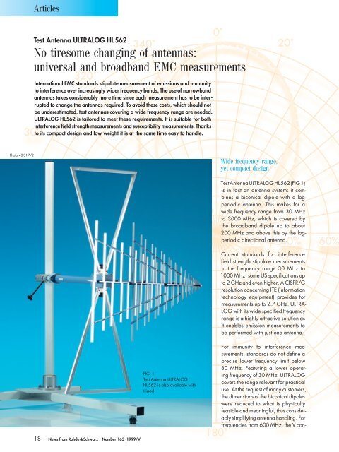
<strong>Test</strong> <strong>Antenna</strong> <strong>ULTRALOG</strong> <strong>HL562</strong><br />
No tiresome changing of antennas:<br />
universal and broadband EMC measurements<br />
International EMC standards stipulate measurement of emissions and immunity<br />
to interference over increasingly wider frequency bands. The use of narrowband<br />
antennas takes considerably more time since each measurement has to be interrupted<br />
to change the antennas required. To avoid these costs, which should not<br />
be underestimated, test antennas covering a wide frequency range are needed.<br />
<strong>ULTRALOG</strong> <strong>HL562</strong> is tailored to meet these requirements. It is suitable for both<br />
interference field strength measurements and susceptibility measurements. Thanks<br />
to its compact design and low weight it is at the same time easy to handle.<br />
Photo 43 317/2<br />
Wide frequency range,<br />
yet compact design<br />
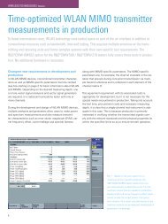
<strong>Test</strong> <strong>Antenna</strong> <strong>ULTRALOG</strong> <strong>HL562</strong> (FIG 1)<br />
is in fact an antenna system: it combines<br />
a biconical dipole with a logperiodic<br />
antenna. This makes for a<br />
wide frequency range from 30 MHz<br />
to 3000 MHz, which is covered by<br />
the broadband dipole up to about<br />
200 MHz and above this by the logperiodic<br />
directional antenna.<br />
Current standards for interference<br />
field strength stipulate measurements<br />
in the frequency range 30 MHz to<br />
1000 MHz, some US specifications up<br />
to 2 GHz and even higher. A CISPR/G<br />
resolution concerning ITE (information<br />
technology equipment) provides for<br />
measurements up to 2.7 GHz. ULTRA-<br />
LOG with its wide specified frequency<br />
range is a highly attractive solution as<br />
it enables emission measurements to<br />
be performed with just one antenna.<br />
FIG 1<br />
<strong>Test</strong> <strong>Antenna</strong> <strong>ULTRALOG</strong><br />
<strong>HL562</strong> is also available with<br />
tripod<br />
For immunity to interference measurements,<br />
standards do not define a<br />
precise lower frequency limit below<br />
80 MHz. Featuring a lower operating<br />
frequency of 30 MHz, <strong>ULTRALOG</strong><br />
covers the range relevant for practical<br />
use. At the request of many customers,<br />
the dimensions of the biconical dipoles<br />
were reduced to what is physically<br />
feasible and meaningful, thus considerably<br />
simplifying antenna handling. For<br />
frequencies from 600 MHz, the V con-<br />
18 News from <strong>Rohde</strong> & <strong>Schwarz</strong> Number 165 (1999/V)
Articles<br />
35<br />
340˚<br />
0˚<br />
20˚<br />
600 MHz<br />
30<br />
320˚<br />
40˚<br />
<strong>Antenna</strong> factor (dB/m)<br />
25<br />
20<br />
15<br />
280˚<br />
300˚<br />
20%<br />
40%<br />
60%<br />
60˚<br />
80˚<br />
80% 100%<br />
10<br />
260˚<br />
Relative field strength<br />
100˚<br />
5<br />
240˚<br />
120˚<br />
0<br />
30 100 1000 3000<br />
Frequency (MHz)<br />
220˚<br />
200˚<br />
180˚<br />
160˚<br />
140˚<br />
E plane<br />
H plane<br />
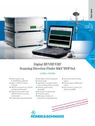
FIG 2 <strong>Antenna</strong> factor of <strong>HL562</strong> in free<br />
space (typical values)<br />
FIG 3 Directional pattern of <strong>HL562</strong> (here at<br />
600 MHz) is almost rotationally symmetrical in<br />
E and H planes<br />
figuration of the directional antenna<br />
makes for increased gain despite the<br />
small dimensions of the antenna (FIG 2).<br />
Gain enhancement compensates for<br />
the reduction in system sensitivity that<br />
would otherwise make itself clearly<br />
felt because of the cable attenuation,<br />
which increases with frequency (see<br />
FIG 2, typical characteristic of antenna<br />
factor).<br />
Attractive features make for<br />
versatile use<br />
<strong>ULTRALOG</strong>’s wide frequency range<br />
and its capability of performing field<br />
strength measurements plus immunity<br />
measurements at field strengths up to<br />
10 V/m make for highly versatile use of<br />
this compact test antenna. But <strong>HL562</strong><br />
has further qualities: the V confi guration<br />
of the dipoles not only results<br />
in improved antenna gain but also<br />
yields largely rotationally symmetrical<br />
and congruent directional patterns in<br />
the E plane and the H plane above<br />
200 MHz. This may eliminate the need<br />
for a second measurement, which is<br />
defined in some test specifications if<br />
polarization is not symmetrical.<br />
CISPR 16-1 stipulates polarization isolation<br />
of at least 20 dB to keep measurement<br />
uncertainties to a minimum (in this<br />
case, an error lower than approx. 1 dB<br />
is obtained). <strong>ULTRALOG</strong> complies with<br />
this stipulation of course. Products with<br />
polarization isolation of only 14 dB<br />
have an additional error of 2 dB, which<br />
is unacceptable for many measurement<br />
tasks.<br />
Another innovative feature of <strong>HL562</strong><br />
is its construction. There are no loose<br />
dipoles because the complete log-periodic<br />
antenna is made of one piece.<br />
The longer dipoles are interconnected<br />
by means of transverse braces, ensuring<br />
high mechanical stability despite<br />
the compact and lightweight design.<br />
Calibration of course<br />
<strong>ULTRALOG</strong> <strong>HL562</strong> is factory-calibrated<br />
prior to delivery. Calibration is performed<br />
to ANSI C63.5 in the frequency<br />
range 30 MHz to 150 MHz<br />
above conductive plane, and to DIN<br />
45003 in the remaining frequency<br />
range in free space. In both cases the<br />
three-antenna method is used and a<br />
tolerance analysis carried out. Calibration<br />
data are supplied with the antenna<br />
as hardcopy and on disk to ensure<br />
simple transfer of the specific antenna<br />
data to the test system.<br />
Klaus Fischer;<br />
Dr Christof Rohner<br />
Condensed data of <strong>Test</strong> <strong>Antenna</strong> <strong>ULTRALOG</strong> <strong>HL562</strong><br />
Frequency range<br />
30 MHz to 3000 MHz<br />
Polarization<br />
linear<br />
Cross-polarization suppression<br />
20 dB<br />
Gain<br />
typ. 8 dB<br />
Reader service card 165/06<br />
News from <strong>Rohde</strong> & <strong>Schwarz</strong> Number 165 (1999/V) 19