DESIGN RATIONALE - Biomet
DESIGN RATIONALE - Biomet
DESIGN RATIONALE - Biomet

Create successful ePaper yourself
Turn your PDF publications into a flip-book with our unique Google optimized e-Paper software.
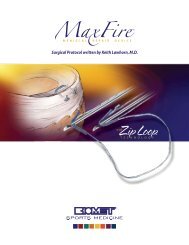
<strong>DESIGN</strong><br />
<strong>RATIONALE</strong>
INTRODUCTION<br />
THE VANGUARD COMPLETE<br />
KNEE SYSTEM WAS ENGINEERED<br />
TO FIT THE ENTIRE POPULATION,<br />
REGARDLESS OF RACE, GENDER<br />
OR STATURE.<br />
Beginning with the AGC ® and continuing with the Maxim ®<br />
and Ascent, <strong>Biomet</strong>’s total knee systems have a long and<br />
rich clinical heritage. With the introduction of the Vanguard <br />
Complete Knee System, <strong>Biomet</strong> has taken this proven<br />
clinical heritage and combined it with state-of-the-art<br />
design features to produce the most comprehensive<br />
total knee system available. With the introduction of<br />
Microplasty ® and Premier instrumentation platforms and<br />
advancements such as our patented Slidex ® Technology,<br />
the Vanguard Complete Knee System is the surgeon’s<br />
ally in exceeding the demands of today’s active joint<br />
replacement patient.<br />
ADVANCING TECHNOLOGY<br />
When designing the Vanguard Complete Knee System,<br />
every feature in the femur, patella and tibia was reviewed<br />
for potential performance enhancement in all patient<br />
populations. Many clinically successful features found in<br />
earlier <strong>Biomet</strong> ® total knee systems remain the same in the<br />
Vanguard Complete Knee System. However, many more<br />
features were added.<br />
Patella/Femoral Joint<br />
The Vanguard femoral component has four main design<br />
features incorporated into the sagittal profi le:<br />
• Rounded sagittal profi le<br />
• Deeper, swept-back trochlear groove<br />
• Longer trochlear groove<br />
• Wide proximal trochlear groove<br />
Each of these variables improves lateral release rates,<br />
extensor moment arm, patella alignment and patella tracking,<br />
while reducing the potential for patellar tendon irritation.<br />
Rounded Sagittal Profi le<br />
Two distinct femoral designs have evolved over time: an<br />
anatomic (box-like) femoral profi le and a more swept-back<br />
(rounder) sagittal profi le.
A round sagittal profi le as found in the Vanguard knee may<br />
be more forgiving to the retinaculum by not over tensioning<br />
the soft tissues.<br />
Anatomic (Gold) vs. Swept-back (Gray) Sagittal Profi le<br />
Deeper/Swept-back Trochlear Groove<br />
The trochlear groove is a critical design feature for patella<br />
performance. Translation of the trochlear groove posteriorly<br />
in the femur has shown to resist patella crepitus and clunk. 1<br />
The Vanguard trochlear groove has been designed to<br />
sweep back posteriorly for better patellar performance.<br />
Longer Trochlear Groove<br />
The trochlear groove has also Standard Trochlear Groove (Gold)<br />
been lengthened to further<br />
support the patella in deep<br />
fl exion. This longer trochlear<br />
groove also better supports<br />
the quadriceps tendon. In<br />
deep fl exion, a shorter<br />
trochlear groove, as in the<br />
Maxim ® knee, will articulate<br />
Deeper and Longer Trochlear<br />
on the quadriceps tendon at<br />
Groove (Gray)<br />
the junction of the trochlear<br />
groove and posterior stabilized<br />
(PS) box at 75 to 80 degrees of<br />
fl exion. In the Vanguard knee, the<br />
junction does not articulate with<br />
30<br />
the quadriceps tendon until 105<br />
to 120 degrees of fl exion.<br />
% of Females<br />
20<br />
10<br />
0<br />
Size 55<br />
Wider Proximal Trochlear Groove<br />
Patellar capture during<br />
fl exion must be balanced<br />
0–15°<br />
with the need for less<br />
patellar constraint in<br />
extension. The Vanguard <br />
knee provides for this<br />
balance through a widened<br />
trochlear fl oor to reduce Q-angle<br />
constraining forces in<br />
extension and a 6.5 degree valgus angulation of the patella<br />
track. “Valgus angulation has been shown to reduce the<br />
patellar shear stresses.” 2<br />
In addition to a wider proximal trochlear groove, the<br />
Vanguard knee offers a comprehensive approach to<br />
patellofemoral mechanics that includes femoral retinacular<br />
relief, a lateralized trochlea and a clinically proven dome<br />
patellar component. The aggregate of these features<br />
produces a component that provides for excellent<br />
patellar tracking (within 0–15 degrees of valgus) regardless<br />
of the patient’s Q-angle. 3 Retinacular relief minimizes<br />
soft tissue tension, reducing the potential need for a<br />
lateral release.<br />
The narrow anterior fl ange maintains a small profi le to<br />
reduce the likelihood of femoral overhang. To further<br />
address overhang, the Vanguard knee features rounded<br />
corners on the anterior fl ange. Proper femoral fi t with<br />
respect to overhang is a primary concern for patients with<br />
smaller anatomies, most commonly found in the female<br />
population. The Vanguard knee addresses this by offering<br />
a femoral component that grows medial/lateral in 2.4mm<br />
increments between its smallest six sizes, which have shown<br />
to be the most commonly utilized sizes for female patients.<br />
Size 57.5 Size 60 Size 62.5 Size 65 Size 67.5 Size 70 Size 72.5 Size 75 Size 80<br />
Most Commonly Used Femoral Sizes Based on 1,611 Vanguard Knees Implanted in Females 3<br />
1
Articulation Features<br />
Coronal Geometry Features<br />
The Vanguard knee system<br />
provides a fully congruent<br />
(coronally), moderately<br />
dished articulation, which<br />
reduces polyethylene<br />
stresses while still allowing<br />
physiological motion.<br />
The patented 1:1 condylar<br />
1:1 Tibial-Femoral Contact<br />
geometry provides surgical<br />
fl exibility by allowing tibial-femoral interchangeability.<br />
The Vanguard cruciate retaining (CR) and posterior<br />
stabilized (PS) femurs have complete size interchangeability<br />
with their respective primary bearings.*<br />
Increased Range of Motion<br />
The Vanguard knee<br />
has been designed to<br />
accommodate patients<br />
who require an above<br />
average range of motion.<br />
The femoral posterior<br />
condyle geometry will<br />
allow for 145 degrees of<br />
fl exion. The Vanguard <br />
knee is able to achieve this<br />
145 Degrees Range of Motion with<br />
Primary Bone Cuts<br />
high range of motion without the need to resect an<br />
additional 2mm of posterior condyles. The Vanguard <br />
tibial bearings have a deeper anterior relief to minimize<br />
the potential for patella impingement during high fl exion.<br />
To increase contact area with axial rotation, the Vanguard <br />
knee features a rotated bearing surface articulation. As<br />
compared to a linear articulation, a rotated articulation<br />
increases the contact area by 13 percent. 3<br />
High Flexion Patellar Tendon Relief<br />
Rotated Tibial Articulating Surface<br />
The coronal geometry features a softened intercondylar<br />
(medial and lateral) edge. This radius enhancement produces<br />
increased contact area for the patella when articulating<br />
on the condyles in fusion. Finite element analysis has<br />
demonstrated a 25 percent reduction in patella contact<br />
pressure compared to the Maxim ® Total Knee design. 3<br />
Proportional Posterior Condyles<br />
The posterior condyles grow<br />
proportionally in size. This provides<br />
better bone coverage and reduces<br />
overstuffi ng the fl exion gap in<br />
smaller femurs or undersizing the<br />
posterior condyles in larger femurs.<br />
Better coverage of the posterior<br />
condyles aids in achieving high<br />
fl exion and restoring femoral offset.<br />
The posterior condyle geometry has also been optimized<br />
to provide larger contact areas in deep fl exion. Larger<br />
contact areas will dissipate forces more effectively. 4<br />
Finite Element Analysis Demonstrates a Gradual Dispersion of Forces<br />
Along the Patella 3<br />
2<br />
*With the exception of the Vanguard Anterior Stabilized (AS) Bearing.
Intermediate Femoral Sizes<br />
The Vanguard knee has introduced four additional<br />
intermediate sized primary femoral components to<br />
enhance the traditional femoral offering.<br />
Ten Vanguard femoral component sizes, combined with<br />
nine Vanguard tibial component sizes, while maintaining<br />
complete interchangeability among all sizes, provide<br />
intraoperative fl exibility to fi t varying patient anatomies of<br />
both the femur and the tibia independently. The end result<br />
is a complete knee system that is the most fl exible on the<br />
market, allowing a custom fi t for the entire population,<br />
regardless of race, gender or stature.<br />
Mid-fl exion cam engagement avoids cam/post contact<br />
during high cycle activities but ensures stability during high<br />
moment activities.<br />
Enhanced Anterior Lip<br />
To help resist paradoxical anterior femoral slide during gait,<br />
the anterior lip of the tibial bearing is more prominent.<br />
This is achieved by moving the anterior radius posteriorly.<br />
The anterior lip provides resistance for the femoral condyles,<br />
preventing anterior slide. This cradling effect controls the<br />
femoral component on the articulating surface without<br />
sacrifi cing freedom of rotation. The combination of 45<br />
degrees cam engagement with (anterior lip) stability<br />
optimizes cam/post engagement, limiting premature wear<br />
of the tibial post.<br />
Ten Femoral Sizes<br />
More Prominent Anterior Lip (Dark Gray)<br />
Specific Posterior Stabilized<br />
Design Features<br />
A multitude of design features affect the performance<br />
of a cam and spine type of posterior stabilized knee.<br />
The following design features are key elements in the<br />
Vanguard PS system:<br />
Cam and Post Engagement<br />
The cam on the PS femoral<br />
component is designed<br />
to engage the spine on the<br />
tibial component at 45<br />
degrees of fl exion. Gait<br />
analysis demonstrates that<br />
weight bearing phase occurs<br />
from 0 to 45 degrees. 5 After<br />
stance phase (weight bearing),<br />
the cam engages the spine<br />
to provide stability and<br />
45 Degrees Cam and Spine<br />
increase quadriceps effi ciency,<br />
Engagement<br />
specifi cally during activities<br />
such as ascending and descending stairs.<br />
Low Cam Engagement/High Dislocation Height<br />
The cam engages relatively low on the tibial post and<br />
remains low throughout full range of motion. This decreases<br />
the forces at the tibial-bone interface and at the locking<br />
mechanism while maintaining a high dislocation height. The<br />
dislocation height of the Vanguard PS is never less than<br />
17.3mm at 90 degrees of fl exion or greater. The Vanguard <br />
PS component allows for 10 degrees of hyperextension<br />
before anterior post impingement.<br />
45°<br />
60°<br />
75°<br />
90°<br />
Cam Contact Points<br />
3
Post Geometry Designed for Stability,<br />
Reduced Wear<br />
The PS post geometry is rounded to minimize forces on<br />
the post due to rotation of the femur and resultant rotation<br />
of the PS box. According to mechanical wear test<br />
simulation, the Vanguard PS bearing had a 71 percent<br />
reduction in gravimetric wear at 5.5 million cycles as<br />
compared to a standard square post design geometry. 3<br />
PS Box Resection Options<br />
The Vanguard knee offers<br />
several options for PS box<br />
resection. The choices of<br />
standard bone conserving or<br />
closed box cuts are available<br />
for the open box femoral<br />
component. The standard cut<br />
allows for a parallel cut to be<br />
made relative to the distal<br />
resection, whereas the bone<br />
conserving cut produces an<br />
angled cut, conserving bone<br />
near the anterior chamfer area.<br />
Closed<br />
Open<br />
Bone<br />
Conserving<br />
Two PS Box Resection Options<br />
Rounded PS Post<br />
PS Plus—An Additional Constraint Option<br />
The Vanguard PS femoral component will accept the<br />
standard PS bearing as well as the PS plus, a more<br />
constrained bearing. The PS plus bearing is indicated for<br />
use in a primary situation when more stability is desired to<br />
resist rotation and varus/valgus lift-off.<br />
The standard PS post does not constrain the femur in<br />
rotation or varus/valgus lift-off.<br />
The Premier instrumentation also provides the option of<br />
milling the PS box resection. The mill conserves bone at the<br />
corners of the box, resulting in a fi ve percent reduction in<br />
box volume as well as reducing the stress risers created by<br />
square corners.<br />
Premier PS Femoral Mill Box Resection<br />
Note: The PS plus bearing does not articulate with the<br />
Vanguard SSK femoral component and is not indicated<br />
for use as a revision bearing.<br />
Square Corner<br />
PS Bearing<br />
4<br />
PS Plus Bearing<br />
Round Corner<br />
Finite Element Analysis Demonstrating Lower Concentration of Stress at<br />
Corner of Box
Specific Cruciate Retaining<br />
Design Features<br />
The Vanguard CR femoral component incorporates<br />
all design and articulation features of the posterior<br />
stabilized design as well as key features specifi c to the<br />
CR femoral component.<br />
Removable Femoral Lugs<br />
The femoral lugs on the Vanguard CR are removable.<br />
This feature allows for augmentation if required in<br />
primary total knee arthroplasty or in the revision of a<br />
failed unicompartmental knee arthroplasty.<br />
Two Fixation Options<br />
The Vanguard CR and PS femoral components are<br />
available in two fi xation options: Interlok ® roughened fi nish<br />
for cement fi xation or PPS ® Porous Plasma Spray Coating<br />
for cementless fi xation.<br />
The Vanguard CR and PS porous options have been<br />
cleared by the FDA for cementless fi xation.<br />
Cruciate Retaining Bearing Options<br />
The options for tibial bearings include standard (with three<br />
degrees posterior slope built into the articulating surface),<br />
posterior lipped and anterior stabilized.<br />
Standard CR (Three-Degrees Posterior Slope)<br />
Removable CR Lugs<br />
CR Lipped (No Slope)<br />
Anterior Stabilized Bearing (No Slope)<br />
These options provide a multitude of choices to meet<br />
patient needs and surgeon preferences.<br />
Augment Attached to CR Knee<br />
5
Specific Vanguard SSK Revision<br />
Femoral Design Features<br />
While the Vanguard SSK femoral component integrates all<br />
the primary femoral component design features, there are a<br />
few differentiating design features specifi c to the Vanguard <br />
SSK revision femoral component.<br />
Stability<br />
The SSK constrained bearing offers a large swept back<br />
tibial post that provides stability and continued constraint in<br />
deep fl exion. The large tibial post also maintains increased<br />
post/box contact. At 90 degrees of fl exion, 17mm of the<br />
post remains in the box.<br />
SSK Femoral Component<br />
SSK Bearing Options<br />
The Vanguard SSK revision system offers two bearing<br />
options: the SSK PS tibial bearing and the SSK constrained<br />
tibial bearing. This feature allows the surgeon intraoperative<br />
fl exibility in the case of collateral defi ciencies.<br />
The SSK PS bearing provides only posterior stabilization<br />
with the Vanguard SSK revision femur.<br />
SSK Tibial Post in Box<br />
SSK Femoral Component Extended Cam<br />
The Vanguard SSK<br />
femoral component<br />
adds an additional<br />
3mm of material on<br />
the cam. This provides<br />
for a higher dislocation<br />
height, up to 23mm,<br />
prior to dislocation.<br />
Stem Boss Angle<br />
Extended Cam<br />
The Vanguard SSK femur has a fi ve-degree stem valgus<br />
angle which will accept multiple stem lengths in straight and<br />
curved profi les to match the patient’s anatomy.<br />
SSK PS Bearing and SSK Constrained Bearing<br />
The SSK constrained bearing is designed to allow<br />
for +/-1 degree of varus/valgus lift-off and +/-0.5 degree<br />
of rotational freedom.<br />
Stem Boss Angle<br />
6
Femoral Augmentation<br />
Individual distal (5mm, 10mm and 15mm thicknesses) and<br />
posterior (5mm and 10mm thicknesses) augmentation<br />
blocks are available for patients with inadequate bone stock.<br />
5mm<br />
10mm<br />
15mm<br />
Oxidation may negatively impact the fatigue characteristics<br />
of the polyethylene, causing delamination.<br />
<strong>Biomet</strong> was the fi rst company to use an inert gas, argon,<br />
to replace oxygen during the sterilization and packaging<br />
processes. The use of argon reduces the degradative effects<br />
of oxygen present in polyethylene-bearing designs.<br />
Furthermore, gamma sterilization in an argon atmosphere<br />
has been shown to decrease wear over EtO sterilized<br />
polyethylene by 44 percent. 15 ArCom ® polyethylene has<br />
been clinically proven to be more resistant to wear,<br />
delamination and oxidation. 16–19<br />
5mm<br />
10mm<br />
Augments<br />
CLINICAL HERITAGE<br />
ArCom ® Polyethylene<br />
<strong>Biomet</strong> has made the commitment to Direct Compression<br />
Mold all tibial bearings* within the Vanguard system to<br />
minimize the potential for wear and oxidative breakdown.<br />
<strong>Biomet</strong>’s ability to combine clinically proven polyethylene 6–10<br />
with the Vanguard knee system punctuates <strong>Biomet</strong>’s<br />
engineering-driven approach. Knee wear is thought to<br />
predominately be a fatigue mechanism, which may lead to<br />
delamination and pitting of the bearing surface. Traditional<br />
machining of tibial articulations has been shown to be<br />
detrimental to the long-term performance of knee<br />
replacements. 11–14 The cutting tools used in machining<br />
shear the polyethylene and pull the material apart, creating<br />
regions of residual stress. This residual stress may sensitize<br />
the material to localized breakdown and oxidation.<br />
Wear Testing<br />
Polyethylene Thickness/Locking<br />
Mechanism Design<br />
Meding, et al. demonstrated excellent long-term results<br />
with 4.4mm minimum thickness Direct Compression<br />
Molded tibial bearings. 7 The Vanguard knee system provides<br />
a minimum of 6mm of polyethylene thickness in its primary,<br />
posterior stabilized and revision components. Thicknesses<br />
for all polyethylene sizes are listed in the polyethylene size/<br />
thickness chart.<br />
+<br />
=<br />
Size<br />
Thickness<br />
10 12 14 16 18 20 22 24<br />
Extruded Bar Stock Machining Oxidized Cross-Section<br />
Polyethylene<br />
Articulating 6 8 10 12 14 16 18 20<br />
Thickness(mm)<br />
+<br />
=<br />
Polyethylene Size/Thickness<br />
Resin Direct Molding Non-Oxidized Cross-Section<br />
*May not be applicable to custom products.<br />
7
Effective polyethylene thickness is determined by evaluating<br />
not only thickness at the center of the tibial condyle but<br />
also by measuring the periphery of the polyethylene insert.<br />
Many currently manufactured components provide adequate<br />
thickness at the center but compromise thickness around<br />
the edges due to the design of the locking mechanism. Feng,<br />
et al. have found that the most severe polyethylene wear<br />
occurs at the periphery, where the component had a raised<br />
metal edge. 20 These concerns have been addressed in the<br />
<strong>Biomet</strong> modular tibial trays. The peripheral polyethylene<br />
thickness is maintained by locating the locking mechanism<br />
anteriorly and within the intercondylar area. Concerns have<br />
been raised about modularity and bearing micromotion as<br />
a contributor to osteolysis and early failure. 21–26 <strong>Biomet</strong>’s<br />
locking mechanism compresses the polyethylene bearing<br />
against the tray, thereby reducing micromotion. Published<br />
literature has also shown the <strong>Biomet</strong> ® locking mechanism to<br />
be the most stable overall. 22,23<br />
Micro Macro Macro<br />
M/L 59 63 67 71 75 79 83 87 91<br />
A/P 38 41 43 46 48 51 53 56 58<br />
<strong>Biomet</strong> Tibial Plate Sizing<br />
Mensch and Amstutz Tibial Sizing 27<br />
Achieving Optimal Bone Coverage<br />
The Vanguard femoral components are based on extensive<br />
cadaver studies. Mensch and Amstutz 27 reviewed 200<br />
cadaver knees which served as the basis of AGC, ® Maxim ®<br />
and Vanguard femoral component sizing. Four additional<br />
sizes are offered with the Vanguard system, reducing the<br />
interval between sizes in the center of the usage distribution.<br />
Anterior Compressive Locking Mechanism<br />
Tibial Tray Sizing<br />
Many knee systems offer a variety of tibial tray sizes.<br />
However, few systems offer consistent, close sizing. The<br />
Vanguard knee system offers nine tibial sizes that change<br />
in consistent 4mm M/L intervals, based on the work of<br />
Mensch and Amstutz. 27 A scientifi c study was conducted<br />
that examined eight tibial tray designs, six symmetrical and<br />
two asymmetrical. 28 Incavo, et al. showed that the sizing<br />
rationale for the AGC ® Total Knee System, which is closely<br />
paralleled by the Vanguard system, offers optimal coverage<br />
as compared to competitive asymmetrical designs. Of all the<br />
tibial trays tested, the AGC ® knee was ranked as the best in<br />
total coverage, covering 80.8 percent of the tibial surface. 28<br />
Bell Curve of Femoral Coverage with Additional Intermediate Sizes<br />
8
Patellar Articulation<br />
Ritter, Lombardi, Insall, Ranawat and others have<br />
shown excellent long-term results with domed patellar<br />
designs. 6,8,29–31 The domed patella is more forgiving in<br />
placement than other designs and can more reliably<br />
provide congruent contact.<br />
Component Fixation<br />
The Vanguard knee system incorporates two types<br />
of fi xation fi nishes. The Interlok ® fi nish allows for proper<br />
cement interdigitation into the surface for a more<br />
secure bond.<br />
Interlok ® Finish<br />
Domed Patella<br />
Series A Patellas<br />
The Vanguard total knee system offers multiple patella<br />
options. Patellas are available in one and three peg options<br />
in standard thicknesses and in a thinner version which is on<br />
average 1.5mm thinner than the standard patella.<br />
Since its introduction in 1981, <strong>Biomet</strong>’s PPS ® Porous Plasma<br />
Spray Coating has been used by surgeons throughout the<br />
world to achieve better fi xation on a multitude of products<br />
including the AGC ® knee, Maxim ® knee, Ascent knee,<br />
Taperloc ® hip, and Bio-Modular ® total shoulder. At follow-up,<br />
surgeons are observing extremely low rates of osteolysis<br />
and nearly 100 percent survivorship at over 10 years with<br />
PPS ® coating prostheses. 32–35<br />
Series A Standard One and Three Peg Patellas<br />
PPS ® Coating<br />
9
Additionally, it has been clinically proven that titanium<br />
porous surfaces facilitate increased ingrowth as compared<br />
to similar cobalt chrome surfaces. 36<br />
<strong>Biomet</strong>’s proprietary PPS ® Porous Plasma Spray application<br />
is unique in comparison to competitors’ techniques in that<br />
only the titanium alloy powder is heated, not the substrate<br />
of the implant. The sintering process (used to apply beads<br />
and wire mesh coatings) compromises the substrate’s<br />
strength and results in a greatly decreased ability to withstand<br />
in-vivo stresses. 37–46 <strong>Biomet</strong>’s plasma spray process maintains<br />
the implant’s inherent fatigue strength. 37–46<br />
Tibial Tray Options<br />
Tibial Augments<br />
Fatigue Strength<br />
Offset Tibial Tray<br />
The <strong>Biomet</strong> ® offset tibia offers offset immediately from the<br />
bottom of the tibial tray and can be positioned 360 degrees<br />
for exact offset placement. The offset is available in neutral,<br />
2.5mm and 5.0mm.<br />
Tibial Baseplate Options<br />
<strong>Biomet</strong>’s tibial tray options are the most comprehensive<br />
on the market today. Primary tibial trays are made from<br />
both titanium and cobalt chrome alloys. Titanium baseplates<br />
come either with an Interlok ® fi nish or a PPS ® coating to<br />
enhance bone ingrowth. PPS ® coated baseplates accept<br />
up to four 6.5mm cancellous bone screws for enhanced<br />
fi xation when a cementless tibial component is desired. The<br />
porous, stemmed and offset tibial plates can be used with<br />
block or wedge augments. All augments are fi xed to the<br />
baseplates via bolts, allowing a mechanical lock between<br />
the tray and augments. Cobalt chrome baseplate options<br />
come in either fi xed I-beam or fi xed cruciate fi n with an<br />
Interlok ® fi nish.<br />
Neutral<br />
5.0mm Offset<br />
2.5mm Offset<br />
Offset Trays and Adaptors<br />
10
Stem Options<br />
The modular primary tray provides for the intraoperative<br />
selection of the stem to match the specifi c needs of the<br />
patient. The combination of a Morse-type taper and screw<br />
fi xation helps maintain a solid connection between the stem<br />
and plate. When more fi xation is desired, the stemmed tray<br />
or offset tray will accept stem extensions.<br />
Modular Tibial Tray Stems<br />
Stem Extensions<br />
11
REFERENCES<br />
1. Ip, D. et al. Comparison of two total knee prostheses on the incidence of patella<br />
clunk syndrome. International Orthopaedics. 26(1): 48–51, 2002.<br />
2. Peterslidge, W.J. et al. The Effect of Trochlear Design on Patellofemoral Shear and<br />
Compressive Forces in Total Knee Arthroplasty. Clinical Orthopaedics and Related<br />
Research. 309: 136–45, 1994.<br />
3. Data on fi le at <strong>Biomet</strong>.*<br />
4. Bartel, D.L. et al. The Effect of Conformity, Thickness, and Material on Stresses in<br />
Ultra-High Molecular Weight Components for Total Joint Replacement. Journal of<br />
Bone and Joint Surgery. 68-A(7): 1041, 1986.<br />
5. Banks, S.A. et al. Function of Total Knee Replacements During Activities of Daily<br />
Living. Scientifi c Exhibit at AAOS, Orlando, Florida, 2000.<br />
6. Ritter, M. et al. Long-Term Followup of Anatomic Graduated Cruciate-Retaining Total<br />
Knee Replacement. Clinical Orthopaedics and Related Research. 388: 51–57, 2001.<br />
7. Meding, J. et al. Total Knee Arthroplasty with 4.4mm of Tibial Polyethylene. Clinical<br />
Orthopaedics and Related Research. 388: 112–117, 2001.<br />
8. Robertson, O. et al. The Swedish Knee Arthroplasty Register, A Nation-Wide Study<br />
of 30,003 Knees 1976–1992, Department of Orthopaedics, University Hospital,<br />
Lund, Sweden. Acta Orthopaedica Scandanavica. 65: 375–386, 1994.<br />
9. Paavolainen, P. Long-Term Results of Total Joint Arthroplasty. Results of a 15 year<br />
follow-up on a nationwide registration programme in Finland with 67,714 TJA’s.<br />
National Agency for Medicines Medical Device Center. 1–11, 1994.<br />
10. Emerson, R. Higgins, L. Head, W. The AGC ® Total Knee Prosthesis at Average 11 Years.<br />
Journal of Arthroplasty. 15(4): 418–423, 2000.<br />
11. Ritter, M. Direct Compression Molded Polyethylene for Total Hip and Knee<br />
Replacements. Clinical Orthopaedics and Related Research. 2001: 94–100, 2001.<br />
12. Weber, A. et al. A Study of Polyethylene and Modularity Issues in Over 1000 PCR<br />
Knees at 5–11 Years. The Journal of Arthroplasty. 17(8): 987–991, 2002.<br />
13. Berzins, A. et al. Surface Damage in Machined Ram-Extruded and Net-Shape Molded<br />
Retrieved Polyethylene Tibial Inserts of Total Knee Replacements. Journal of Bone and<br />
Joint Surgery. 84-A(9): 1534–1540, 2002.<br />
14. Won, C.H. et al. Effect of Resin Type and Manufacturing Method on Wear of<br />
Polyethylene Tibial Components. Clinical Orthopaedics and Related Research. 376:<br />
461–171, July 2000.<br />
15. Schroeder, D.W. Pozorski, K.M. Hip Simulator testing of Isostatically Molded<br />
UHMWPE: Effect of ETO And Gamma Irradiation. 42nd Annual Meeting,<br />
Orthopaedic Research Society, Atlanta, Georgia, February 19–22, 1996.<br />
16. Beading, L. Direct Molded Components Shown to Resist Oxidation. Orthopedics<br />
Today. 17(4): 1997.<br />
17. Furman, B.D. et al. (Abstract) Effect of Resin Type and Manufacturing Method on<br />
UHMWPE Oxidation and Quality at Long Aging and Implant Times. 43rd Annual<br />
Meeting Orthopaedic Research Society, San Francisco, CA, Feb. 9–13, 1997.<br />
18. Beading, L. Polyethylene-Related Failure: A Challenge to TKA. Orthopedics Today.<br />
16–21, 1996.<br />
19. Ritter, M.A. et al. Long-Term Survival Analysis of a Posterior Cruciate-Retaining Total<br />
Condylar Total Knee Arthroplasty. Clinical Orthopaedics and Related Research. 309:<br />
136–145, 1994.<br />
20. Feng, E.L. et al. Progressive Subluxation and Polyethylene Wear in Total Knee<br />
Replacements with Flat Articular Surfaces. Scientifi c Exhibit, 59th Annual AAOS<br />
Meeting, San Francisco, California, February 1993.<br />
24. Pagnano, M. et al. Tibial Osteolysis Associated With the Modular Tibial Tray of a<br />
Cemented PS Total Knee Replacement. Journal of Bone and Joint Surgery. 83-A(10):<br />
1545–1548, Oct. 2001.<br />
25. Engh, G. et al. In Vivo Deterioration of Tibial Baseplate Locking Mechanisms in<br />
Contemporary Modular Total Knee Components. Journal of Bone and Joint Surgery.<br />
83-A(11): 1660–1665 Nov. 2001.<br />
26. Mikulak, S. et al. Loosening and Osteolysis with the PFC ® Posterior Cruciate<br />
Substituting Total Knee Replacement. Journal of Bone and Joint Surgery. 83-A(3):<br />
398–403, 2001.<br />
27. Mensch, J. Amistutz, H. Knee Morphology as a Guide to Knee Replacement. Clinical<br />
Orthopaedics and Related Research. 12: 231–41, 1975.<br />
28. Incavo, S.J. et al. Tibial Plateau Coverage in Total Knee Arthroplasty. Clinical Orthopaedics<br />
and Related Research. 229: 81–85, 1994.<br />
29. Insall, J.N. et al. Total Condylar Knee Replacement: Preliminary Report. Clinical<br />
Orthopaedics and Related Research. 276: 26–32 1992.<br />
30. Ranawat, C.S. et al. Impact of Modern Technique on Long-Term Results of Total<br />
Condylar Knee Arthroplasty. Clinical Orthopaedics and Related Research. 309:<br />
131–135, 1994.<br />
31. Lombardi, A.V. Jr. et al. The PCL: To Save or Not to Save. A Mid- to Long-term<br />
Survivorship Comparison Within a Single Total Knee Arthroplasty System. 69th<br />
AAOS Scientifi c Exhibit, Dallas, Texas, Feb. 13–17, 2002.<br />
32. Head; et al. A Titanium Cementless Calcar Replacement Prosthesis in Revision<br />
Surgery of the Femur: 13 Year Experience. Journal of Arthroplasty. 16(8): 2001.<br />
33. Head, W.C. et al. Twelve Years with a Primary Press Fit Titanium Stem. AAOS Poster<br />
#PE400, March 2001.<br />
34. Mauerhan; et al. Integral ® Porous Femoral Stem. Journal of Arthroplasty. (3): 1997.<br />
35. Meding; et al. Minimum 10-Year Follow-Up of a Straight-Stemmed, Plasma-Sprayed,<br />
Titanium Alloy, Uncemented Femoral Component. AAOS Poster #PE396, March<br />
2001.<br />
36. Hoffman, A. Response of Human Cancellous Bone to Identically Structured<br />
Commercially Pure Titanium and Cobalt Chromium Alloy Porous-Coated Cylinders.<br />
Clinical Materials. 14: 101–115, 1993.<br />
37. Yue, et al. Journal of Biomedical Materials Research. Vol. 18, 1984.<br />
38. Luedemann, <strong>Biomet</strong> In-House Testing, 1987.*<br />
39. <strong>Biomet</strong>, Porous Coating Technical Report, 1986.*<br />
40. Luedemann, <strong>Biomet</strong> In-House Testing, 1992.*<br />
41. Luedemann, HAP Coated Plasma Sprayed Porous Coated Rotating Beam Fatigue<br />
Strength and the Effect of Soaking in Physiological Saline Solution. <strong>Biomet</strong> Technical<br />
Report, 1993.<br />
42. Zimmer, Technology in Orthopaedics; Fatigue and Porous Coated Implants. 1984.<br />
43. Young and Pilliar, Transactions of the 16th Annual Meeting of the Society for<br />
Biomaterials, 1990.<br />
44. Pilliar, Clinical Orthopaedics. No. 176, June, 1983.<br />
45. Georgette and Davidson, Journal of Biomedical Materials Research. Vol. 20, 1986.<br />
46. Gustavson, in Hungerford et al. Total Hip Arthroplasty: A New Approach, 1984.<br />
21. Wasielewski, R. et al. Tibial Insert Undersurface as a Contributing Source of Poly<br />
Wear Debris. Clinical Orthopaedics and Related Research. 345: 53–59,1997.<br />
22. Parks, N. et al. Modular Tibial Insert Micromotion. Clinical Orthopaedics and Related<br />
Research. 356: 10–15, 1998.<br />
23. Sosa, M.A. Wasielewski, R.C. Micromotion Between the Tibial Tray and the<br />
Polyethylene Insert. Fifth World Biomaterial Congress, Toronto, Canada,<br />
May 29–June 2, 1996.<br />
*Bench test results are not necessarily indicative of clinical performance.<br />
12
Microplasty, ® Maxim, ® Mono-Lock, Ascent, Slidex, ® Interlok, ® Bio-Modular, ® ArCom, ®<br />
Premier, PPS, ® Vanguard and AGC ® are trademarks of <strong>Biomet</strong> Manufacturing Corp.<br />
This material is intended for the sole use and benefi t of the <strong>Biomet</strong> sales force and<br />
physicians. It is not to be redistributed, duplicated or disclosed without the express<br />
written consent of <strong>Biomet</strong>.<br />
For product information, including indications, contraindications, warnings, precautions<br />
and potential adverse effects, see the package insert and <strong>Biomet</strong>’s website.<br />
DrivenByEngineering<br />
P.O. Box 587, Warsaw, IN 46581-0587 • 800.348.9500 ext. 1501<br />
©2007 <strong>Biomet</strong> Orthopedics, Inc. All Rights Reserved • www.biomet.com<br />
Form No. Y-BMT-1014/041507/M