

S2-AM121 - DDKS Industries, hydraulic components distributor
S2-AM121 - DDKS Industries, hydraulic components distributor
S2-AM121 - DDKS Industries, hydraulic components distributor

You also want an ePaper? Increase the reach of your titles
YUMPU automatically turns print PDFs into web optimized ePapers that Google loves.
Assembly Procedures Continued Series 24, 30<br />
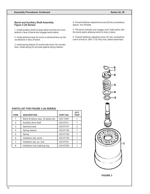
Barrel and Auxiliary Shaft Assembly<br />
Figure 3 (24 Series)<br />
1. Install auxiliary shaft (2) large spline end first into counterbore<br />
in face of barrel and engage barrel spline.<br />
2. Install spherical seat (3) round or spherical face up into<br />
counterbore in face of barrel.<br />
4. Thread holddown adjustment screw (6) into counterbore<br />
approx. four threads.<br />
5. Tilt barrel vertically and engage main shaft spline with<br />
the barrel spline allowing barrel to drop in place.<br />
6. Thread holddown adjusting screw (6) into counterbore<br />
until it is flush to .060" (1.52 mm) max. below barrel face.<br />
3. Install spring retainer (4) socket side down into counterbore,<br />
install spring (5) and seat against spring retainer.<br />
PARTS LIST FOR FIGURE 3 (24 SERIES)<br />
QTY<br />
ITEM DESCRIPTION PART NO. P24P<br />
1 Barrel & sleeve assy. 24 series only <strong>S2</strong>3-12091 1<br />
2 Auxiliary drive shaft 033-57211 1<br />
3 Spherical seat 033-57147 2<br />
4 Spring retainer 033-57138 1<br />
5 Spring 033-57136 1<br />
6 Holddown adj. screw 033-57139 1<br />
7 Holddown adj. scr. lock 033-57241 1<br />
8 Holddown lock retaining ring 033-57239 1<br />
FIGURE 3<br />
12


