

S2-AM121 - DDKS Industries, hydraulic components distributor
S2-AM121 - DDKS Industries, hydraulic components distributor
S2-AM121 - DDKS Industries, hydraulic components distributor

Create successful ePaper yourself
Turn your PDF publications into a flip-book with our unique Google optimized e-Paper software.
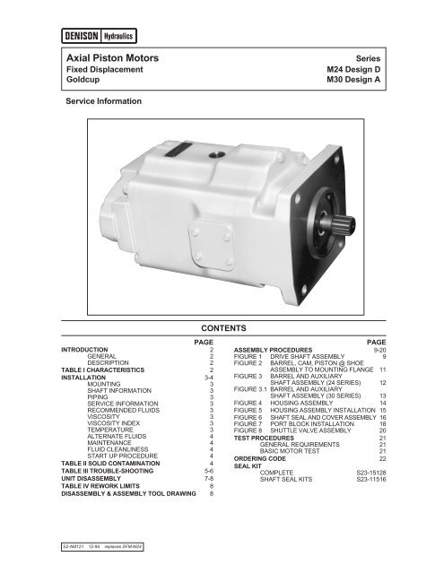
Axial Piston Motors<br />
Fixed Displacement<br />
Goldcup<br />
Series<br />
M24 Design D<br />
M30 Design A<br />
Service Information<br />
CONTENTS<br />
PAGE<br />
INTRODUCTION 2<br />
GENERAL 2<br />
DESCRIPTION 2<br />
TABLE I CHARACTERISTICS 2<br />
INSTALLATION 3-4<br />
MOUNTING 3<br />
SHAFT INFORMATION 3<br />
PIPING 3<br />
SERVICE INFORMATION 3<br />
RECOMMENDED FLUIDS 3<br />
VISCOSITY 3<br />
VISCOSITY INDEX 3<br />
TEMPERATURE 3<br />
ALTERNATE FLUIDS 4<br />
MAINTENANCE 4<br />
FLUID CLEANLINESS 4<br />
START UP PROCEDURE 4<br />
TABLE II SOLID CONTAMINATION 4<br />
TABLE III TROUBLE-SHOOTING 5-6<br />
UNIT DISASSEMBLY 7-8<br />
TABLE IV REWORK LIMITS 8<br />
DISASSEMBLY & ASSEMBLY TOOL DRAWING 8<br />
PAGE<br />
ASSEMBLY PROCEDURES 9-20<br />
FIGURE 1 DRIVE SHAFT ASSEMBLY 9<br />
FIGURE 2 BARREL, CAM, PISTON @ SHOE<br />
FIGURE 3<br />
ASSEMBLY TO MOUNTING FLANGE 11<br />
BARREL AND AUXILIARY<br />
SHAFT ASSEMBLY (24 SERIES) 12<br />
FIGURE 3.1 BARREL AND AUXILIARY<br />
SHAFT ASSEMBLY (30 SERIES) 13<br />
FIGURE 4 HOUSING ASSEMBLY 14<br />
FIGURE 5 HOUSING ASSEMBLY INSTALLATION 15<br />
FIGURE 6 SHAFT SEAL AND COVER ASSEMBLY 16<br />
FIGURE 7 PORT BLOCK INSTALLATION 18<br />
FIGURE 8 SHUTTLE VALVE ASSEMBLY 20<br />
TEST PROCEDURES 21<br />
GENERAL REQUIREMENTS 21<br />
BASIC MOTOR TEST 21<br />
ORDERING CODE 22<br />
SEAL KIT<br />
COMPLETE <strong>S2</strong>3-15128<br />
SHAFT SEAL KITS <strong>S2</strong>3-11516<br />
<strong>S2</strong>-<strong>AM121</strong> 12-94 replaces SFM-M24
Introduction Series 24, 30<br />
General<br />
This manual contains installation, operation, maintenance<br />
and overhaul instructions for Denison Hydraulics Goldcup<br />
24 and Goldcup 30 constant volume motors. The Denison<br />
Hydraulics Goldcup 24 and Goldcup 30 axial piston motors<br />
feature advance design concepts which are time proven<br />
and provide for advance pumping and control concepts.<br />
The instructions contained in this manual cover complete<br />
disassembly and reassembly of the unit. Before proceeding<br />
with the disassembly or reassembly of any unit, this<br />
manual should be studied in order to become familiar with<br />
proper order and parts nomenclature.<br />
Description<br />
The Goldcup motor is a fixed displacement, axial piston<br />
design which uses hydrostatically balanced piston shoes.<br />
This feature serves to lubricate as well as absorb much<br />
of the force generated by the shoes pressing against the<br />
cam, thereby increasing service life of the unit. Rotation<br />
of the unit is bi-directional.<br />
TABLE I TYPICAL CHARACTERISTICS<br />
Specification Term Goldcup 24 Goldcup 30<br />
Displacement in. 3 /rev 24.6 30.6<br />
cm 3 /rev (403) (501.4)<br />
Pressure Ports A & B max. continuous psi 5000 5000<br />
bar (345) (345)<br />
max. intermittent psi 5000 5000<br />
bar (345) (345)<br />
Speed, max. continuous @ full stroke RPM 2100* 1800<br />
Flow, Ports A or B GPM @ 2100 RPM 223.6 @ 1800 RPM 238<br />
(theoretical) L/min. (846) (901)<br />
Rotary Inertia lb/in 2 818 974<br />
kg/m 2 (0.239) (0.285)<br />
Torque, Theoretical in/lb 392 487<br />
per 100 PSI (6.9 bar) N•m (43) (55)<br />
at 5000 PSI (345 bar) in/lb 19576 24351<br />
N•m (2158) (2752)<br />
Power, Theoretical @ 5000 PSI (345 bar) hp 31.1 38.64<br />
at 100 RPM kW (23.1) (28.8)<br />
Power, Theoretical at 5000 PSI (345 bar) hp 621.3 695**<br />
at Max. RPM kW (463.5) (518)**<br />
Torque Efficiency approx. stalled % theoretical 81 81<br />
running % theoretical 93 93<br />
Mounting-4 bolt flange SAE F F<br />
Shaft-Spline / Keyed SAE F F<br />
Fluid Connection Ports A & B in 2 2<br />
SAE-4 bolt pad for 6000 psi split flange mm (50.8) (50.8)<br />
(414 bar)<br />
Weight lbs. 640 660<br />
kg. (290) (300)<br />
*On R & O Oils (Rust and Oxidation Inhibitor)<br />
** @ 1800 RPM<br />
2
Installation Series 24, 30<br />
Mounting<br />
This motor is designed to operate in any position. The<br />
mounting hub and four bolt mounting flange are in full conformance<br />
with SAE standard. The motor shaft must be in<br />
alignment with the shaft of the driven load and should be<br />
checked with a dial indicator. The mounting pad or adaptor<br />
into which the fluid motor pilots must be concentric with<br />
the motor shaft to prevent bearing failure. This concentricity<br />
is particularly important if the shaft is rigidly connected<br />
to the driven load without a flexible coupling.<br />
Shaft Information<br />
Splined: The shafts will accept a maximum misalignment<br />
of 0.006" TIR (.15 mm). Angular misalignment at the male<br />
and female spline axes must be less than ±.002 (0.05<br />
mm) per one inch radius. The coupling interface must be<br />
lubricated. Denison Hydraulics recommends lithium<br />
molydisulfate or similar grease. The female coupling<br />
should be hardened to 45-50 Rc and must conform to<br />
SAE-J498B (1971) Class 1 flat root side fit.<br />
Keyed: High strength heat treated keys must be used.<br />
Replacement keys must be hardened to 27-34 Rc. The key<br />
corners must be chamfered .030"-.040" (.75-1 mm) at 45°<br />
to clear radii that exist in the keyway.<br />
Keyed types of shafts will accept a side load of 1000 lbs.<br />
(454 kg) at the center of the key, with a B10 life of 9,880<br />
hours at 1800 RPM or 11,856 hours at 1500 RPM.<br />
NOTE: Do not impact coupling to force it onto the<br />
shaft.<br />
Piping<br />
Connect inlet and outlet lines to the port block of the motor.<br />
The fluid connections are:<br />
System Ports: 2" (50.8 mm)<br />
6000 PSI (414 bar), SAE<br />
4 bolt flange<br />
Other: SAE straight thread, O-ring seal.<br />
See installation drawing for sizes.<br />
The maximum case pressure is 75 PSI (5.17 bar) continuous,125<br />
PSI (8.6 bar) intermittent.<br />
NOTE: High case pressure will result in reduced B-<br />
10 life of the shaft bearing.<br />
It is recommended that the case leakage line be connected<br />
to the port located between the two system ports on the<br />
port block, but it may be connected to the top or bottom<br />
connections on the motor housing.<br />
The case leakage line must be of sufficient size to prevent<br />
back pressure in excess of 75 PSI (5.7 bar) and returned<br />
to the reservoir below the surface of the oil as far from the<br />
supply suction as possible. All fluid lines, whether pipe, tubing,<br />
or hose must be adequate size to assure free flow<br />
through the motor. We recommend 20 ft (6.09 M) max. per<br />
second for main flow and 6 ft. (1.8 M) max. limit per second<br />
for drain lines. Pressure rating of piping hose must be<br />
adequate for service duty required.<br />
An undersized outline line will create back pressure and<br />
cause improper operation. Flexible hose lines are recommended.<br />
If rigid piping is used, the workmanship must be<br />
accurate to eliminate strain on the port block or to the fluid<br />
connections. Sharp bends in the lines must be eliminated<br />
wherever possible. All system piping must be cleaned with<br />
solvent or equivalent before installing motor. Make sure the<br />
entire <strong>hydraulic</strong> system is free of dirt, lint, scale, or other<br />
foreign material. Flushing with a large temporary high pressure<br />
loop filter is recommended.<br />
CAUTION: Do not use galvanized pipe. Galvanized<br />
coating can flake off with continued use.<br />
Service Information<br />
These <strong>hydraulic</strong> products are designed to give long<br />
dependable service when properly applied and their systems<br />
properly maintained. These general instructions apply<br />
to typical systems. Specific instructions for particular equipment<br />
can be developed from them.<br />
Recommended Fluids<br />
The fluid recommended for use in these pumps and motors<br />
has a petroleum base and contains agents which provide<br />
oxidation inhibition and anti-rust, anti-foam and de-aerating<br />
properties as described in Denison Hydraulics standard<br />
HF-1. Where anti-wear additive fluids are specified, see<br />
Denison Hydraulics standard HF-0.<br />
Viscosity:<br />
Max. at cold start—7500 SUS (1600 Cst)<br />
(at low pressure, low speed)<br />
Max. at full power—750 SUS (160 Cst)<br />
Optimum for max. life—140 SUS (30 Cst)<br />
Minimum at full power—60 SUS (10 Cst)<br />
Viscosity Index:<br />
90 V.I. minimum. Higher values extend the range of operating<br />
temperature but may reduce the service life of the<br />
fluid.<br />
Temperature<br />
Determined by the viscosity characteristics of the fluid<br />
used. Because high temperatures degrade seals, reduce<br />
the service life of the fluid and create hazards, fluid temperatures<br />
should not exceed 180°F (82°C) at the case<br />
drain.<br />
3
Installation Continued Series 24, 30<br />
Alternate Fluids<br />
Some applications require fire-resistant fluids. They will<br />
give good service if the system is originally designed for<br />
their use. Permissible fire resistant fluids include:<br />
Type<br />
Denison Hydraulics Standard<br />
Water-in-oil invert emulsions<br />
HF-3<br />
Water glycol solutions<br />
HF-4<br />
Phosphate esters<br />
HF-5<br />
Consult Denison Hydraulics for design requirements and<br />
warranty limitations for service with this class of fluids.<br />
See Denison Hydraulics bulletin SPO-AM305 for more information.<br />
Maintenance<br />
This motor is self-lubricating and preventative maintenance<br />
is limited to keeping system fluid clean by changing filters<br />
frequently. Keep all fittings and screws tight. Do not operate<br />
at pressures and speeds in excess of the recommended<br />
limit. If the motor does not operate properly, check the<br />
Trouble Shooting Chart before attempting to overhaul the<br />
unit. Overhauling is relatively simple and may be accomplished<br />
by referring to the Disassembly, Rework Limits of<br />
Wear Parts and Assembly Procedures.<br />
Fluid Cleanliness<br />
Fluid must be cleaned before and continuously during operation<br />
by filters that maintain a cleanliness level of NAS 1638<br />
Class 8. This approximately corresponds to ISO 17/14.<br />
This fluid level cleanliness can usually be accomplished by<br />
the effective use of 10 micron filters. Better cleanliness levels<br />
will significantly extend the life of the <strong>components</strong>. As<br />
contaminant generation may vary with each application,<br />
each must be analyzed to determine proper filtration to<br />
maintain the required cleanliness level.<br />
2. Check alignment of drive.<br />
3. Visually inspect <strong>components</strong> and lines for possible<br />
damage.<br />
4. Check reservoir for cleanliness and clean as required.<br />
White glove test on all internal surfaces is recommended.<br />
5. Check fluid level and fill as required with filtered fluid at<br />
least as clean as that recommended. Fill motor case with<br />
clean oil prior to starting.<br />
6. Check oil cooler and activate it, if included in circuit.<br />
Check fluid temperature.<br />
7. Reduce pressure settings of pressure control. Make<br />
sure accurate pressure readings can be made at appropriate<br />
places.<br />
8. If solenoids in system, check for actuation.<br />
9. Start pump drive first by jogging prime mover. Make sure<br />
pump and motor fill properly.<br />
10. Bleed system of air. Recheck fluid level.<br />
11. Cycle unloaded machine at low pressure and observe<br />
actuation (at low speed, if possible).<br />
12. Increase pressure settings gradually in steps. Check<br />
for leaks in all lines especially in pump and motor inlet lines.<br />
13. Make correct pressure adjustments.<br />
14. Gradually increase speed. Be alert for trouble as indicated<br />
by changes in sounds, system shocks and air in fluid.<br />
Inspect oil surface with a good light while in operation. There<br />
must be no surface broken with oil surges and limit surface<br />
air bubbles to occasional.<br />
15. Equipment is operational.<br />
Start Up Procedure for New Installation<br />
1. Read and understand the instruction manual. Identify<br />
<strong>components</strong> and their functions.<br />
TABLE II<br />
COMPARISON OF SOLID CONTAMINATION CLASSIFICATION SYSTEMS<br />
NATIONAL AEROSPACE STANDARD (NAS) 1638<br />
4
Table III Trouble-shooting Chart Series 24, 30<br />
Trouble-Shooting<br />
Component problems and circuit problems are often interrelated.<br />
An improper circuit may operate with apparent success<br />
but will cause failure of a particular component within<br />
it. The component failure is the effect, not the cause of<br />
the problem.<br />
This general guide is offered to help in locating and eliminating<br />
the cause of problems by studying their effects:<br />
Effect of Trouble Possible Cause Fault Which Needs Remedy<br />
Noisy Motor Air in Fluid Leak in suction line<br />
Leak at shaft seal<br />
Low fluid level<br />
Turbulent fluid<br />
Return lines above fluid level<br />
Gas leak from accumulator<br />
Excessive pressure drop in the inlet line<br />
from a pressurized reservoir<br />
Suction line strainer acting as air trap<br />
Cavitation in motor<br />
rotating group<br />
Misaligned shaft<br />
Fluid too cold<br />
Fluid too viscous<br />
Fluid too heavy<br />
Shaft speed too high<br />
Suction line too small<br />
Suction line collapsed<br />
Operating altitude too high<br />
Boost or replenishment pressure too low<br />
Replenishment flow too small for<br />
dynamic conditions<br />
Faulty installation<br />
Distortion in mounting<br />
Axial interference<br />
Faulty coupling<br />
Excessive overhung loads<br />
Mechanical fault in motor Piston and shoe looseness or failure<br />
Bearing failure<br />
Incorrect port plate selection or index<br />
Erosion on barrel ports and port plate Air in fluid See above<br />
Cavitation<br />
See above<br />
High wear in motor Excessive loads Reduce pressure settings<br />
Reduce speeds<br />
Contaminant particles in fluid Improper filter maintenance<br />
Filters too coarse<br />
Introduction of dirty fluid to system<br />
Reservoir openings<br />
Improper reservoir breather<br />
Improper line replacement<br />
Improper fluid<br />
Fluid too thin or thick for operating<br />
temperature range<br />
Breakdown of fluid with<br />
time/temperature/shearing effects<br />
Incorrect additives in new fluid<br />
Destruction of additive effectiveness with<br />
chemical aging<br />
Improper repair<br />
Incorrect parts<br />
Incorrect procedures, dimensions, finishes<br />
(Continued)<br />
5
Table III Continued Series 24, 30<br />
Effect of Trouble Possible Cause Fault Which Needs Remedy<br />
High Wear in motor Unwanted water in fluid Condensation<br />
Faulty breather/strainer<br />
Heat exchanger leakage<br />
Faulty clean-up, practice<br />
Water in makeup fluid<br />
Pressure shocks Cogging load Mechanical considerations<br />
Worn relief valve<br />
Needed repairs<br />
Worn compensator<br />
Needed repairs<br />
Slow response in check valves Replace or relocate<br />
Excessive decompression Improve decompression control<br />
energy rates<br />
Excessive line capacitance Reduce line size or lengths.<br />
(line volume, line stretch, Eliminate hose<br />
accumulator effects)<br />
Barrel blow-off<br />
Recheck hold-down, rotating group,<br />
drain pressure<br />
Heating of fluid Excessive motor leakage Recheck case drain flow and repair as<br />
required<br />
Fluid too thin<br />
Improper assembly, port timing<br />
Relief valve<br />
Heat exchanger<br />
Reservoir<br />
Set too low (compared to load or to compensator)<br />
Instability caused by back pressure,<br />
worn parts<br />
Water turned off or too little flow<br />
Water too hot<br />
Fan clogged or restricted<br />
Efficiency reduced by mud or scale deposits<br />
Intermittent <strong>hydraulic</strong> fluid flow<br />
Too little fluid<br />
Entrained air in fluid<br />
Improper baffles<br />
Insulating air blanket that prevents<br />
heat rejection<br />
Heat pickup from adjacent equipment<br />
6
Unit Disassembly Series 24, 30<br />
Disassembly<br />
The instructions contained in this section cover a complete<br />
teardown of the subject motor. Disassemble only as far as<br />
necessary to replace or repair any worn parts. A bench or<br />
similar suitable surface capable of supporting unit should<br />
be used. Disassembly area should be clean.<br />
CAUTION: On 24 Series units relax barrel holddown<br />
prior to removal of shaft seal or main shaft. Failure to<br />
follow this procedure may result in motor failure.<br />
NOTE: The four main assembly bolts (1, Figure 9) are<br />
torqued to 450 ft. lbs. (610 N•m) These bolts should<br />
be loosened prior to removing unit for disassembly.<br />
Shuttle Valve Assembly<br />
See Figure 7<br />
1. Remove three screws (13) and remove valve assembly<br />
from port block.<br />
24 Series Barrel Holddown<br />
See Figure 3<br />
1. Remove holddown lock retainer ring (8, Figure 3). (Use<br />
internal snap ring pliers.)<br />
2. Remove four screws (1, Figure 7) and two screws (8,<br />
Figure 7).<br />
NOTE: There is a preload from the barrel holddown<br />
which will lift the port block approx. 1 ⁄8" at release.<br />
3. Carefully lift and remove port block (2) and port plate (4,<br />
Figure 7).<br />
CAUTION: The port plate may cling to the barrel<br />
face because of oil film. Do not allow the port plate<br />
to fall and become damaged.<br />
4. Remove the face plate and face plate pins (2, 1, Figure<br />
5) from the face of the barrel assembly.<br />
5. Remove holddown adjusting screw lock (7, Figure 3).<br />
6. Lock main shaft (1, Figure 6) from turning. Use special<br />
tool T2, slip over auxiliary shaft (2, Figure 3) and engage<br />
dowels into holddown adjusting screw (6, Figure 3). Loosen<br />
load but do not remove.<br />
7. Remove two bolts (8, Figure 7) holding housing and<br />
flange together.<br />
8. Barrel assembly can be removed by lifting with aux.<br />
shaft. The pistons will remain with the cam assembly.<br />
These parts are precision finished and must be handled<br />
with extreme care!<br />
9. Using special tool T2, holddown assembly can be<br />
removed from barrel. Remove adjusting screw (6, Figure<br />
3), spring (5), retainer (4), spherical seat (3) and auxiliary<br />
shaft (2).<br />
30 Series Barrel Holddown<br />
See Figure 3.1<br />
1. Remove four screws (1, Figure 7) and two screws<br />
(8, Figure 7).<br />
NOTE: There is a preload from the barrel holddown<br />
which will lift the port block approx. 1 ⁄8" at release.<br />
2. Carefully lift and remove port block (2) and port plate<br />
(4, Figure 7).<br />
CAUTION: The port plate may cling to the barrel<br />
face because of oil film. Do not allow the port plate<br />
to fall and become damaged.<br />
3. Remove the face plate and face plate pins (2, 1, Figure<br />
5) from the face of the barrel assembly.<br />
4. Loosen six screws gradually in alternating sequence.<br />
CAUTION: Holddown is under preload. Do not remove<br />
screws completely.<br />
5. Insert three #10-32 screws into the three #10-32 tapped<br />
holes. Alternately turn in screws till tapered retainer releases.<br />
A loud crack sound should be heard when it releases.<br />
6. Lock main shaft (1, Figure 6) from turning. Use special<br />
tool T2, slip over auxiliary shaft (2, Figure 3.1) and engage<br />
dowels into holddown adjusting screw retainer (6, Figure<br />
3.1). Loosen load but do not remove.<br />
7. Remove two bolts (8, Figure 7) holding housing and<br />
flange together.<br />
NOTE: Do not damage gasket faces in process. Do<br />
not remove the retaining screws or bearing from the<br />
housing unless bearing is damaged and replacement<br />
is necessary.<br />
8. Barrel assembly can be removed by lifting with auxiliary<br />
shaft. The pistons will remain with the cam assembly.<br />
These parts are precision finished and must be handled<br />
with extreme care!<br />
NOTE: Do not damage gasket faces in process. Do<br />
not remove the retaining screws or bearing from the<br />
housing unless bearing is damaged and replacement<br />
is necessary.<br />
7
Unit Disassembly Continued Series 24, 30<br />
TABLE IV Rework Limits of Wear Parts<br />
Max. Rework<br />
From Original<br />
Min. Dimension<br />
24 and 30 in 3 Dimension After Rework<br />
Port plate face .010" (.254 mm) .735" (18.67 mm)<br />
Shoe retainer face .005" (.127 mm) .494" (12.55 mm)<br />
*Piston shoe face (pocket) .002" (.051 mm)(24 in 3 ) .018" (.457 mm)(24in 3 )<br />
Creep plate face .010" (.254 mm) .365" (9.27 mm)<br />
Face plate None Replace<br />
* NO REWORK PERMITTED ON 30 in 3 SHOE.<br />
IMPORTANT:<br />
The port plate both sides, face finish must be 8 microinches, (0, 20 µmm) flat within .00006 (0, 0015) and parallel within<br />
.001 (0, 025 mm) T.I.R.<br />
The creep plate wear face finish must be 5 microinches (127 µmm), flat within .0005 (0, 012 mm) and parallel to the backside<br />
with .001 (0, 0254 mm) T.I.R.<br />
The shoe retainer wear face finish must be 32 microinches (813 µmm), and flat within .0005 (0, 012 mm) (must not be<br />
convex).<br />
The piston shoes wear face finish must be 30 microinches (760 µmm), and must be lapped in a set with the retainer plate,<br />
all shoe sole thicknesses to be within .001 (0, 0254 mm) after lapping. The maximum permissible shoe and piston axial<br />
looseness is .010 (0, 254 mm).<br />
The special retaining ring service kit (<strong>S2</strong>3-12629) may be required to control shoe holddown clearance.<br />
Drive Shaft<br />
See Figure 6<br />
1. Remove four screws (5), seal retainer (2), gaskets (4),<br />
and stationary part of shaft seal assembly (4). Refer to<br />
view of item 3.<br />
2. Remove the carbon ring and the remainder of the shaft<br />
seal from the shaft.<br />
3. Remove shaft and bearing assembly (1).<br />
Cam and Piston/Shoe Assembly<br />
1. Remove the retaining ring (2, figure 2), thrust washer<br />
(3), piston and shoe assembly (4) and creep plate (5) from<br />
the cam (6).<br />
2. Remove the cam from the mounting flange by carefully<br />
tilting mounting flange on its side and removing plugs (12,<br />
Figure 2) with O-rings (9, Figure 2) using 1 ⁄4-20 threaded<br />
rod as a puller, and removing screws (10, Figure 2) attaching<br />
cradle to mounting flange.<br />
Disassembly & Assembly Tool Drawings<br />
T1<br />
T2<br />
Removal & Replacement Tool for H.D. Lock Screw — Barrel H.D. Adjustment Tool<br />
8
Assembly Procedures Series 24, 30<br />
Drive Shaft Assembly<br />
Figure 1<br />
1. Slide the bearing (2) over the short end of the shaft and<br />
seat against the shoulder. Support only the inner race of<br />
the bearing and press on the long end of the shaft to install<br />
bearing.<br />
DO NOT USE EXCESSIVE FORCE. USE EXTREME<br />
CARE PASSING THE RING OVER THE SEAL SURFACE.<br />
2. Install the retaining ring (3) in the groove. Be sure that<br />
the ring is fully seated.<br />
FIGURE 1<br />
<strong>S2</strong>3-12474 #3 Drive Shaft Assembly (spline)<br />
<strong>S2</strong>3-12475 #2 Drive Shaft Assembly (w/keyway)<br />
QTY<br />
ITEM DESCRIPTION PART NO. #1 #2<br />
1 #3 (splined) Drive shaft 033-91139 1 —<br />
#2 (keyed) Drive shaft 033-91140 — 1<br />
2 Shaft bearing 230-82213 1 1<br />
3 Retaining ring 033-71712 1 1<br />
4 Square key 033-71910 — 1<br />
9
Assembly Procedures Continued Series 24, 30<br />
Barrel, Cam to Mounting Flange<br />
Figure 2<br />
3. Position the mounting flange (8) with the large open end<br />
facing up and install two dowel pins (7) in the cradle mounting<br />
surface and one-3/8" (9.52 mm) dia. dowel pin (11) in<br />
the outer edge of the flange.<br />
4. Install the cam (6) over the dowel pins (7) in the mounting<br />
flange. Position cam so that the thick part of the cam is<br />
on the same side as the 3/8" (9.52 mm) dowel (11).<br />
5. With cam installed, tilt mounting flange on its side and<br />
secure with two Soc. Hd. cap screws (10). Torque to 50 ft.-<br />
lbs. (67.8 N•m).<br />
6. Insert plugs (12) with o-rings (9) into Soc. Hd. cap screw<br />
(9) c'bores. Be sure tapped hole in plug (12) is visible after<br />
installation, this is used for removal.<br />
7 Install shaft and bearing assembly (1) Figure 6 (either<br />
splined or keyed as specified) by inserting shaft through<br />
bores, a few light taps are required on the bearing outer<br />
race to completely engage and seat bearing.<br />
NOTE: Do not tap on end of shaft.<br />
Seal Assembly<br />
Figure 6<br />
NOTE: See warning information below<br />
1. The shaft seal is available only as a complete assembly.<br />
Prior to installation examine all the seal parts. Handle<br />
the lapped seal seat and the carbon ring with extreme care.<br />
Both parts must be free of scratches, cracks or other damage.<br />
3. Install the spring (d) against the retainer.<br />
4. Apply oil to the inner surface of the rubber friction ring<br />
(f) and install the shell containing the friction and the carbon<br />
ring (c) over the shaft with the carbon ring exposed.<br />
5. Apply grease to the square section rubber seal (a) and<br />
install on the seat.<br />
6. Install the seat and seal in the seal retainer (2). The<br />
lapped surface of the seat must face the carbon ring.<br />
7. Install the seal retainer assembly and O-ring (4) over the<br />
shaft with the lapped surface against the carbon face.<br />
8. Install the screws (5) and the seal retainer.<br />
9. Depress the seal retainer only far enough to start the<br />
screws and tighten evenly in a criss-cross pattern. Torque<br />
to 30 ft.-lbs. (40.8 N•m).<br />
Seal Replacement<br />
Figure 6<br />
NOTE: 24 Series only–To replace shaft seal only.<br />
1. Remove unit for disassembly.<br />
2. Remove retaining ring (8, Fig. 3).<br />
3. Replace shaft seal. (Follow seal assembly in reverse<br />
order.)<br />
4. After seal is replaced re-install retaining ring (8, Fig. 3).<br />
CAUTION Failure to follow these instructions may result<br />
in pump failure.<br />
2. Install the spring retainer (e) over the shaft and against<br />
the bearing retaining ring.<br />
Mechanical shaft seal assembly procedure<br />
Warning: When installing a new mechanical shaft seal,<br />
exercise care to insure that all of the parts fit together properly.<br />
This is particularly important if the seal was once<br />
assembled and disassembled for some reason. If the rubber<br />
boot, item 4, grips the shaft and doesn't slide on the<br />
shaft, as it is disassembled, then the spring, item 7, can<br />
disengage the shell, item 5, from the band, item 6, so that<br />
they do not re-engage properly when reassembled. Be sure<br />
the shell and the band are properly engaged before<br />
reassembling the seal, and stays engaged during assembly.<br />
Note:<br />
Lubricate seal and shaft with clean <strong>hydraulic</strong> fluid of the<br />
same type that will be used in the system.<br />
10
Assembly Procedures Continued Series 24, 30<br />
Piston/Shoe Assembly to Cam<br />
Figure 2<br />
1. Return the mounting flange to an upright position.<br />
2. Install creep plate (5) over center post on cam (6) chamfered<br />
end first.<br />
3. Insert piston and shoes into retainer and install entire<br />
assembly (4) against creep plate.<br />
6. Position the barrel assembly (1) directly over the pistons.<br />
Starting with the uppermost piston, guide them one<br />
at a time into the barrel bores.<br />
NOTE: Support the barrel on the main shaft but tilted<br />
slightly so as not to allow the barrel to drop and fully<br />
engage the barrel and shaft splines, now the holddown<br />
assembly can be installed without any load against it.<br />
4. Install thrust washer (3), over center post of cam and<br />
against shoe retainer. Grooved side of washer must face<br />
shoe retainer.<br />
5. Install the thickest retaining ring (2) that will fit in the<br />
groove on the rocker cam center post which will allow a<br />
maximum clearance of .002-.005" (.05-.13 mm) between<br />
the creep plate and shoe faces. To check this clearance,<br />
grasp one piston and lift and lift until tight against shoe<br />
retainer. Insert thickness gage. If this clearance is not correct,<br />
select the appropriate retaining ring and repeat the<br />
checking procedure.<br />
NOTE: If metallic thickness gage is used, caution<br />
should be exercised not to scratch shoe face. There<br />
are five different retaining rings available for this tolerance.<br />
Each retaining ring is marked: .081/079"<br />
(2.06/2.01 mm) thick, blue dot; .083/.081" (2.11/2.06<br />
mm) thick, red dot; .087/.085" (2.21/2.16 mm) thick,<br />
green dot; .089/.087" (2.26/2.21 mm) thick, yellow<br />
dot; and .085-.083 (2.16/2.11mm) white dot. The piston<br />
and shoe assembly must be free to rotate 360°<br />
by hand.<br />
PARTS LIST FOR FIGURE 2<br />
ITEM DESCRIPTION PART NO. QTY.<br />
1 Barrel & aux. shaft assy. See Fig. 3 1<br />
2 Retaining ring — use one only 1<br />
.089/.087 thick w/yellow dot (2.26/2.21 mm) 033-71716<br />
.087/.085 thick w/green dot (2.21/2.16 mm) 033-71717<br />
.083/.081 thick w/red dot (2.11/2.06 mm) 033-71718<br />
.081/.079 thick w/blue dot (2.06/2.01 mm) 033-59746<br />
.085/.083 thick w/white dot (2.16/2.11 mm) 033-91130<br />
Retaining ring service kit <strong>S2</strong>3-12629<br />
3 Thrust washer 033-59805 1<br />
4 Piston & shoe assy. P24 S13-44470 1<br />
Piston & shoe assy. P30 <strong>S2</strong>3-12684<br />
5 Creep plate 033-71747 1<br />
6 Cam 033-91148 1<br />
7 Dowel pin 324-24028 2<br />
8 Mounting flange 033-91137 1<br />
9 O-ring 671-00111 2<br />
10 Soc. Hd. cap screw 358-16260 2<br />
11 Dowel pin 324-22416 1<br />
12 Plug 033-57475 2<br />
Figure 2<br />
11
Assembly Procedures Continued Series 24, 30<br />
Barrel and Auxiliary Shaft Assembly<br />
Figure 3 (24 Series)<br />
1. Install auxiliary shaft (2) large spline end first into counterbore<br />
in face of barrel and engage barrel spline.<br />
2. Install spherical seat (3) round or spherical face up into<br />
counterbore in face of barrel.<br />
4. Thread holddown adjustment screw (6) into counterbore<br />
approx. four threads.<br />
5. Tilt barrel vertically and engage main shaft spline with<br />
the barrel spline allowing barrel to drop in place.<br />
6. Thread holddown adjusting screw (6) into counterbore<br />
until it is flush to .060" (1.52 mm) max. below barrel face.<br />
3. Install spring retainer (4) socket side down into counterbore,<br />
install spring (5) and seat against spring retainer.<br />
PARTS LIST FOR FIGURE 3 (24 SERIES)<br />
QTY<br />
ITEM DESCRIPTION PART NO. P24P<br />
1 Barrel & sleeve assy. 24 series only <strong>S2</strong>3-12091 1<br />
2 Auxiliary drive shaft 033-57211 1<br />
3 Spherical seat 033-57147 2<br />
4 Spring retainer 033-57138 1<br />
5 Spring 033-57136 1<br />
6 Holddown adj. screw 033-57139 1<br />
7 Holddown adj. scr. lock 033-57241 1<br />
8 Holddown lock retaining ring 033-57239 1<br />
FIGURE 3<br />
12
Assembly Procedures Continued Series 24, 30<br />
Barrel and Auxiliary Shaft Assembly<br />
Figure 3.1 (30 Series)<br />
1. Install auxiliary shaft (2) spline end first into counterbore<br />
in face of barrel and engage barrel spline.<br />
2. Slide holddown spring assembly (see enlargement for<br />
proper spring arrangement) (3) onto shaft (2).<br />
3. Install spring retainer (4) into counterbore.<br />
4. Thread holddown screw assembly (5) into barrel’s counterbore<br />
approx. four threads.<br />
5. Tilt barrel vertically and engage main shaft spline with<br />
the barrel spline allowing barrel to drop in place.<br />
6. Thread holddown screw assembly (5) into counterbore<br />
until it is .25 (6.35 mm) below barrel face.<br />
PARTS LIST FOR FIGURE 3.1 (30 SERIES)<br />
QTY<br />
ITEM DESCRIPTION PART NO. P30P<br />
1 Barrel & sleeve assy. 30 series only <strong>S2</strong>3-12170 1<br />
2 Auxiliary drive shaft 033-57935 1<br />
3 Holddown spring 035-71713 8<br />
4 Spring retainer 033-91138 1<br />
5 Barrel holddown nut assy. <strong>S2</strong>3-12171 1<br />
FIGURE 3.1<br />
13
Assembly Procedures Continued Series 24, 30<br />
<strong>S2</strong>3-12566 (P24) P23-12175 (P30)<br />
Housing Assembly<br />
Figure 4<br />
1. Clean housing (1) and position on a flat surface with the<br />
large open end up.<br />
2. Apply Loctite primer grade “T” & Loctite retaining compound<br />
#609 per A.P. 01433 to bearing O.D. & bearing bore<br />
of housing. Immediately align & press bearing into housing<br />
bore with a smooth steady force until seated. Install<br />
socket head cap screw (3) with washer (7). Typical two<br />
places. Torque to 30 ft. lbs. (40.8 N•m).<br />
3. Install two dowel pins (4) in the blind holes in the control<br />
cover pads.<br />
4. Repeat step 3 on the opposite side of the housing.<br />
5. Install O-ring (5) and plug (6) in the bottom of housing.<br />
PARTS LIST FOR FIGURE 4<br />
ITEM DESCRIPTION PART NO. QTY.<br />
1 Housing (P24) 033-57150 1<br />
Housing (P30) 033-57925 1<br />
2 Bearing 033-91150 1<br />
3 Screw Soc Head Cap 358-14106 2<br />
5<br />
⁄16 x 18 x 5 ⁄8 w/Nylock<br />
4 Dowel pin 324-21608 4<br />
5 O-ring 691-00920 1<br />
6 Plug 488-35019 1<br />
7 Washer 11 ⁄32 (8.73 mm) 345-10020 2<br />
steel<br />
FIGURE 4<br />
14
Assembly Procedures Continued Series 24, 30<br />
Housing Assembly Installation<br />
Figure 5<br />
1. Install gasket (3) over the dowel pin in the mounting<br />
flange. Do not use gasket compound.<br />
2. Install the housing assembly (4) over the barrel and auxiliary<br />
shaft assembly.<br />
3. Insert two Hex. Hd. cap screws (5) through mounting<br />
flange and into housing. Torque to 100 ft.-lbs. (135.6 N•m).<br />
These must be fully torqued later when main bolts are in<br />
place.<br />
4. Install face plate pins (1) in the holes provided in the barrel<br />
face.<br />
5. Apply clean heavy grease to the surface of the barrel<br />
and install the face plate (2) over the face plate pins. The<br />
surfaces must be absolutely free of scratches, dust or dirt<br />
to prevent excessive leakage. Lubricate pistons with clean<br />
system fluid through the holes in the face plate.<br />
CAUTION: The face plate has a black break-in coating<br />
on top of bronze which is bonded to a steel backing.<br />
Lightly sand the edge of the plate to identify the<br />
bronze coated side. The bronze side should go toward<br />
the port plate.<br />
PARTS LIST FOR FIGURE 5<br />
ITEM DESCRIPTION PART NO. QTY.<br />
1 Face plate pins 033-59747 3<br />
2 Barrel face plate (P24) 033-71748 1<br />
Barrel face plate (P30) 033-57571 1<br />
3 Housing gasket 033-91082 1<br />
4 Housing assembly See Fig. 4 1<br />
5 Hex Hd. screws 306-40009 2<br />
FIGURE 5<br />
15
16<br />
PARTS LIST FOR FIGURE 6<br />
ITEM DESCRIPTION PART NO. QTY.<br />
1 No. 3 Splined shaft assy. <strong>S2</strong>3-12474 1<br />
(See fig. 1)<br />
No. 2 Keyed shaft assy. <strong>S2</strong>3-12475<br />
(See fig. 1)<br />
2 Seal retainer 033-57472<br />
3 Shaft seal 623-00015 1<br />
4 Seal retainer O-ring 671-00246 1<br />
5 Hex. head screw 306-40123 4<br />
6 Nyltite washer 631-45007 8<br />
7 Hex. hd. washer screw 353-25039 8<br />
8 Cover 033-53252 2<br />
9 Gasket 033-91058 2<br />
FIGURE 6<br />
Assembly Procedures Continued Series 24, 30
Assembly Procedures Continued Series 24, 30<br />
Port Block Installation<br />
Figure 7<br />
1. Position the motor with open end of the housing assembly<br />
(6) facing up. Install new gasket (5) on the housing. Do<br />
not use gasket compound.<br />
2. Install two port plate pins (3) in the face of the port block<br />
(2) and the dowel pins (7) into mounting surface of port<br />
block.<br />
3. Insert lifting eyes into tapped holes in each system port<br />
mounting surface.<br />
4. Apply heavy grease to the rear of the port plate (4) and<br />
install over the port plate pins.<br />
5. Temporarily attach port plate to port block by inserting<br />
a cord through one of the 2" (50.8 mm) dia. ports down<br />
through the port block port, around arcuate divider in port<br />
plate, back through port block and tie ends of the cord to<br />
lifting eye. Repeat this step to the other side of the port<br />
plate.<br />
6. Install the port block over the auxiliary shaft and position<br />
onto dowel pins.<br />
7. Install the six bolts (1 & 8) with washers (9, 10). Do not<br />
drop the bolts in place as the threads may be damaged.<br />
Torque bolts evenly. Torque bolts (1) in 50 lb. (67.8 N•m)<br />
increments to 450 ft.-lbs. (610 N•m) and the two bolts (8)<br />
to 120 ft.-lbs. (163 N•m) tightening in turn all six bolts.<br />
Re-torque the two bolts (5) Fig. 5 to 120 ft.-lbs (163 N•m).<br />
PARTS LIST FOR FIGURE 7<br />
ITEM DESCRIPTION PART NO. QTY.<br />
1 Hex head cap screw (P24P) 306-40221 4<br />
Hex head cap screw (P30P) 306-40230 4<br />
2 Port block 033-57898 1<br />
3 Port plate pins 324-21610 2<br />
4 Port plate (24) 033-71751 1<br />
Port plate (30) 033-91149 1<br />
5 Port block gasket 033-91085 1<br />
6 Housing assembly (24) <strong>S2</strong>3-12566 1<br />
Housing assembly (30) <strong>S2</strong>3-12175 1<br />
7 Dowel pin 033-57020 2<br />
8 Hex head cap screw 306-40022 2<br />
9 Washer, Hdn. St’l. 350-10136 2<br />
10 Washer, Hdn. St’l. 350-10135 4<br />
11 Seal/shuttle valve 691-10016 3<br />
Seal/cover 691-10014 2<br />
Seal/cover 691-10019 1<br />
12 Shuttle valve/2 orif. S13-48776 1<br />
Shuttle valve/Int. dr. S13-48273<br />
Cover 033-71649<br />
13 Screw-hex hd./shuttle 306-48273 3<br />
Screw-hex hd./cover 306-40071<br />
14 O-ring 671-00147 1<br />
15 End cover 033-72100 1<br />
16 Retaining ring 356-65082 1<br />
17 O-ring 691-00906 1<br />
18 Hex. soc. plug 488-35041 1<br />
19 O-ring 691-00920 1<br />
20 Plug 488-35019 1<br />
17
Assembly Procedures Continued Series 24, 30<br />
FIGURE 7<br />
18
Assembly Procedures Continued Series 24, 30<br />
Barrel Holddown<br />
Figure 3 & 7 (24 Series)<br />
1. Use special tool T2 and slip over auxiliary shaft and<br />
engage the holes in the holddown adjusting screw (6, figure<br />
3). Carefully tighten until screw bottoms out.<br />
NOTE: The main drive shaft must be held to prevent<br />
barrel assembly from turning. If barrel assembly turns,<br />
the adjustment cannot be made.<br />
2. Back off holddown screw assembly 140°, counter-clockwise.<br />
3. Barrel lift-off is now set at .032" (.81 mm).<br />
4. Remove spanner wrench. Rotate drive shaft, item 31, to<br />
check if any binding occurs.<br />
5. Lock holddown screw assembly in place by tightening<br />
the six socket head cap screws gradually in the following<br />
torque sequence until 65 in.-lbs. (7.4 N•m) torque is<br />
reached.<br />
2. Remove special tool T2 and sight through holddown screw<br />
and note where tooth of auxiliary shaft spline is located.<br />
3. Back off holddown screw (loosen) 5 to 6 spline teeth on<br />
auxiliary shaft (approx. 135°).<br />
NOTE: If barrel holddown has to be reset for any reason<br />
all six socket head cap screws must be loosened<br />
gradually in the same order they were tightened. Do<br />
not remove socket head screws completely. Use the<br />
#10-32 UNF tapped holes in the insert to disengage<br />
insert from holddown screw assembly. Insert must be<br />
loose before resetting barrel holddown.<br />
NOTE: Tapped hole in holddown screw must line up<br />
with space between spline teeth.<br />
4. Barrel lift-off is now set at .030-.036 (.76-.91 mm).<br />
5. Use special tool T1 and thread holddown adjusting screw<br />
lock (7, figure 3) into holddown adjusting screw. Torque to<br />
30 ft.-lbs. (40.7 N•m).<br />
6. Slip holddown lock retaining ring (8, figure 3) over auxiliary<br />
shaft into groove which is located 2 3 ⁄16" (55.2 mm) from<br />
end of shaft.<br />
7. Untie cords holding port plate and remove.<br />
Barrel Holddown<br />
Figure 3.1 & 7 (30 Series)<br />
1. Use special tool T2 and slip over auxiliary shaft<br />
and engage dowels into holddown screw assembly, (5,<br />
Figure 3.1). Carefully tighten clockwise until holddown<br />
screw assembly bottoms out.<br />
**Torque sequence for locking holddown screw assembly.<br />
6. Untie cords holding port plate and remove.<br />
End Cover<br />
Figure 7<br />
1. Apply a light film of oil or grease to O-ring (14) and place<br />
in groove in end cover (15). Insert end cover (15) into bore<br />
of port block.<br />
2. Install retaining ring (16) into groove.<br />
NOTE: The main drive shaft must be held to prevent<br />
barrel assembly from turning. If barrel assembly turns,<br />
the adjustment cannot be made.<br />
19
Shuttle Valve Assembly Series 24, 30<br />
Shuttle Valve Assembly Internal Drain<br />
1. Place valve assembly (12, fig. 7) in a horizontal position<br />
with the O-ring groove up.<br />
2. Press seat (11) in the .500" (12.7 mm) diameter bore<br />
until it is flush with the body surface.<br />
3. Install spring centering washer (4) over each end of<br />
spool.<br />
5. Install springs (3) over ends of spool and into sockets of<br />
centering washers.<br />
6. Lubricate O-rings (2) and install over plugs (1). Install<br />
the plugs over springs and into body.<br />
8. Install spring (9) in spool (10).<br />
9. Lubricate O-ring (8) and install on groove of plug (7) on<br />
internally drained shuttle.<br />
10. Install plug (7) over spring (9) and tighten.<br />
11. Install seal (11, fig. 7) in counterbore in center of shuttle<br />
valve assembly. Hold in place with a coating of grease.<br />
Install the two seals in remaining counterbores.<br />
12. Install orifices, (15) if required.<br />
13. Install the shuttle valve assembly on port block pad and<br />
secure with screws (13). Torque screws to 20 ft.-lbs. (27.2<br />
N•m)<br />
7. Install spool (10) in bore against seat (11).<br />
FIGURE 8<br />
S13-48273 Assembly, Shuttle Valve without orifices<br />
S13-48776 Assembly, Shuttle Valve with orifices<br />
Item Qty. Part No. Description<br />
1 2 488-35002 Plug<br />
2 2 691-00908 O-ring<br />
3 2 033-70515 Spring<br />
4 2 033-70495 Washer, spring centered<br />
5 1 033-70529 Spool<br />
6 1 033-53117 Body<br />
7 1 033-72129 Plug<br />
8 1 691-00906 O-ring<br />
Item Qty. Part No. Description<br />
9 1 033-71923 Spring, relief valve<br />
10 1 033-71925 Spool, relief valve<br />
11 1 033-53154 Seat<br />
12 3 691-10016 Tetraseal<br />
13 3 306-48273 Screws, 5/16-18 x 2 3/4<br />
14 2 345-20004 Shim washer<br />
15 2 033-53523 Orifice .78 (mm) (optional)<br />
20
Test Procedures Series 24, 30<br />
General Requirements<br />
1. Maximum runout between motor shaft and electric motor<br />
shaft .003 T.I.R.<br />
2. Electric motor speed—1800 RPM.<br />
3. Inlet temperature—130° ± 10°F. (54°C ± 4°C).<br />
4. Inlet condition—24 Series<br />
100 to 150 PSI.<br />
(6.9 to 10.3 bar)<br />
30 Series<br />
225 to 275 PSI.<br />
(15.5 to 19 bar)<br />
5. Case pressure 50 PSI ± 5 PSI. (3.4 ± .34 bar).<br />
6. Fluid—200SSU @ 100°F. (37.8°C).<br />
Basic Motor Test<br />
1. Mount motor on test stand. Connect system lines to<br />
motor. Fill case with clean oil. Dry all oil from motor to permit<br />
checking for external leaks.<br />
2. If motor contains a shuttle, replace the hex. plugs on the<br />
shuttle block with hex. socket plugs prior to running test.<br />
After checking leakage, replace plugs. Adjust system pressure<br />
for 1000 PSI (69 bar). Check and record system flow<br />
and case drain flow both directions of rotation. Monitor loop<br />
temperature.<br />
24 Series 30 Series<br />
Maximum System Flow<br />
194 GPM (734 l/m) 241 GPM (912 l/m)<br />
Maximum Case Drain Flow<br />
3 GPM (11.3 l/m) 4 GPM (15 l/m)<br />
3. Break in motor as follows: Run break in for both directions<br />
of rotation.<br />
10 minutes at 1000 PSI (69 bar)<br />
10 minutes at 2500 PSI (172 bar)<br />
10 minutes at 5000 PSI (345 bar)<br />
4. Adjust system pressure to 5000 PSI (345 bar). Check<br />
and record system flow and case drain flow both directions<br />
of rotation.<br />
24 30<br />
Minimum System Flow<br />
180 GPM (680 l/m) 220 GPM (833 l/m)<br />
Maximum Case Drain Flow<br />
5.0 GPM (19 l/m) 6 GPM (23 l/m)<br />
21
22<br />
Notes Series 24, 30
Ordering Code Series 24, 30<br />
M 24 G - 2 N 1 D - 00- M 2 - X X X X X<br />
Motor series<br />
Displacements, max<br />
24-24.6 in 3 /rev., 403 cc/rev.<br />
30-30.6 in 3 /rev., 501.4 cc/rev.<br />
F-Fixed w/o shuttle<br />
G-Fixed displ. w/ shuttle<br />
Designates special<br />
Shuttle Features<br />
M * G<br />
00-Without orifices<br />
02-With orifices<br />
Shaft<br />
SAE-F<br />
2-Keyed<br />
3-Splined<br />
Shaft rotation<br />
(viewed from shaft end)<br />
N-Bi-directional<br />
Fluid class<br />
1-compatible w/Buna N<br />
4-compatible w/EPR<br />
5-compatible w/Viton<br />
Design letter<br />
(assigned by manufacturer)<br />
23
SALES & SERVICE WORLDWIDE


