

S2-AM121 - DDKS Industries, hydraulic components distributor
S2-AM121 - DDKS Industries, hydraulic components distributor
S2-AM121 - DDKS Industries, hydraulic components distributor

You also want an ePaper? Increase the reach of your titles
YUMPU automatically turns print PDFs into web optimized ePapers that Google loves.
Unit Disassembly Continued Series 24, 30<br />
TABLE IV Rework Limits of Wear Parts<br />
Max. Rework<br />
From Original<br />
Min. Dimension<br />
24 and 30 in 3 Dimension After Rework<br />
Port plate face .010" (.254 mm) .735" (18.67 mm)<br />
Shoe retainer face .005" (.127 mm) .494" (12.55 mm)<br />
*Piston shoe face (pocket) .002" (.051 mm)(24 in 3 ) .018" (.457 mm)(24in 3 )<br />
Creep plate face .010" (.254 mm) .365" (9.27 mm)<br />
Face plate None Replace<br />
* NO REWORK PERMITTED ON 30 in 3 SHOE.<br />
IMPORTANT:<br />
The port plate both sides, face finish must be 8 microinches, (0, 20 µmm) flat within .00006 (0, 0015) and parallel within<br />
.001 (0, 025 mm) T.I.R.<br />
The creep plate wear face finish must be 5 microinches (127 µmm), flat within .0005 (0, 012 mm) and parallel to the backside<br />
with .001 (0, 0254 mm) T.I.R.<br />
The shoe retainer wear face finish must be 32 microinches (813 µmm), and flat within .0005 (0, 012 mm) (must not be<br />
convex).<br />
The piston shoes wear face finish must be 30 microinches (760 µmm), and must be lapped in a set with the retainer plate,<br />
all shoe sole thicknesses to be within .001 (0, 0254 mm) after lapping. The maximum permissible shoe and piston axial<br />
looseness is .010 (0, 254 mm).<br />
The special retaining ring service kit (<strong>S2</strong>3-12629) may be required to control shoe holddown clearance.<br />
Drive Shaft<br />
See Figure 6<br />
1. Remove four screws (5), seal retainer (2), gaskets (4),<br />
and stationary part of shaft seal assembly (4). Refer to<br />
view of item 3.<br />
2. Remove the carbon ring and the remainder of the shaft<br />
seal from the shaft.<br />
3. Remove shaft and bearing assembly (1).<br />
Cam and Piston/Shoe Assembly<br />
1. Remove the retaining ring (2, figure 2), thrust washer<br />
(3), piston and shoe assembly (4) and creep plate (5) from<br />
the cam (6).<br />
2. Remove the cam from the mounting flange by carefully<br />
tilting mounting flange on its side and removing plugs (12,<br />
Figure 2) with O-rings (9, Figure 2) using 1 ⁄4-20 threaded<br />
rod as a puller, and removing screws (10, Figure 2) attaching<br />
cradle to mounting flange.<br />
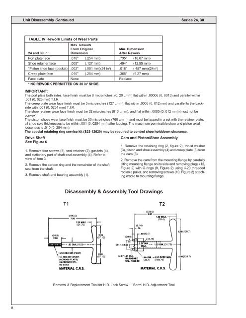
Disassembly & Assembly Tool Drawings<br />
T1<br />
T2<br />
Removal & Replacement Tool for H.D. Lock Screw — Barrel H.D. Adjustment Tool<br />
8


