Van Couver Paper SP-VKP 3-2004 (2).pdf - Shamsher Prakash ...
Van Couver Paper SP-VKP 3-2004 (2).pdf - Shamsher Prakash ...
Van Couver Paper SP-VKP 3-2004 (2).pdf - Shamsher Prakash ...

You also want an ePaper? Increase the reach of your titles
YUMPU automatically turns print PDFs into web optimized ePapers that Google loves.
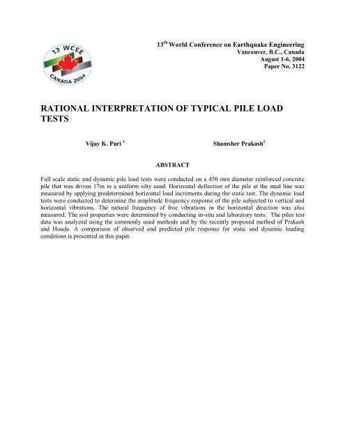
13 th World Conference on Earthquake Engineering<br />
<strong>Van</strong>couver, B.C., Canada<br />
August 1-6, <strong>2004</strong><br />
<strong>Paper</strong> No. 3122<br />
RATIONAL INTERPRETATION OF TYPICAL PILE LOAD<br />
TESTS<br />
Vijay K. Puri 1 <strong>Shamsher</strong> <strong>Prakash</strong> 2<br />
ABSTRACT<br />
Full scale static and dynamic pile load tests were conducted on a 450 mm diameter reinforced concrete<br />
pile that was driven 17m in a uniform silty sand. Horizontal deflection of the pile at the mud line was<br />
measured by applying predetermined horizontal load increments during the static test. The dynamic load<br />
tests were conducted to determine the amplitude frequency response of the pile subjected to vertical and<br />
horizontal vibrations. The natural frequency of free vibrations in the horizontal direction was also<br />
measured. The soil properties were determined by conducting in-situ and laboratory tests. The piles test<br />
data was analyzed using the commonly used methods and by the recently proposed method of <strong>Prakash</strong><br />
and Houda. A comparison of observed and predicted pile response for static and dynamic loading<br />
conditions is presented in this paper.
13 th World Conference on Earthquake<br />
Engineering<br />
<strong>Van</strong>couver, B.C., Canada<br />
August 1-6, <strong>2004</strong><br />
<strong>Paper</strong> No. 3122<br />
RATIONAL INTERPRETATION OF TYPICAL PILE LOAD<br />
TESTS<br />
Vijay K. Puri 1 <strong>Shamsher</strong> <strong>Prakash</strong> 2<br />
SUMMARY<br />
Full scale static and dynamic pile load tests were conducted on a 450 mm diameter reinforced concrete<br />
pile that was driven 17m in a uniform silty sand. Horizontal deflection of the pile at the mud line was<br />
measured by applying predetermined horizontal load increments during the static test. The dynamic load<br />
tests were conducted to determine the amplitude frequency response of the pile subjected to vertical and<br />
horizontal vibrations. The natural frequency of free vibrations in the horizontal direction was also<br />
measured. The soil properties were determined by conducting in-situ and laboratory tests. A comparison<br />
of observed and predicted pile response for static and dynamic loading conditions is presented in the<br />
paper.<br />
INTRODUCTION<br />
Piles are used extensively to support structures for static as well as dynamic loads. Analysis of piles to<br />
resist static lateral loads is generally conducted by using the approach, Reese and Matlock [1] and by<br />
using non-linear p-y curve approach , <strong>Prakash</strong> and Sharma [2]. In the approach suggested by Reese and<br />
Matlock , the constant of the modulus of sub-grade reaction n h becomes a basic parameter. Soil nonlinearity<br />
is accounted for by using strain or deflection dependent values of n h . The soil parameters, n h or<br />
k h are used to determine the lateral load-deflection behavior of pile.<br />
The pile response under dynamic loads can generally be obtained by making simplified spring-mass<br />
models. The soil springs are obtained from the shear modulus of the soil. The non-linearity effects can be<br />
accounted for by using strain dependent values of the shear modulus.<br />
A comparison of the observed and predicted response of a single pile for static and dynamic loading<br />
conditions is presented in this paper. Static lateral load tests were conducted on 450 mm diameter<br />
reinforced concrete pile driven 17m into a deposit of uniform silty sand. Dynamic tests were conducted<br />
on a similar pile by subjecting the pile to horizontal and vertical vibrations. Soil properties such as shear<br />
modulus and the constant of modulus of horizontal sub-grade reaction were determined by conducting insitu<br />
tests. Soil strength parameters were determined by conducting direct shear tests in the laboratory.<br />
Lateral load response of the pile for static loading condition was calculated by using strain (deflection)<br />
dependent values of n h . The dynamic response of the pile was calculated using the approach of Novak<br />
[3,4], Novak and El-Sharnouby [5], and <strong>Prakash</strong> and Puri [6]. The cases of constant shear modulus with<br />
depth (homogenous soil profile) and parabolic shear modulus variation with depth (parabolic soil profile)<br />
1
were considered. The amplitude (shear strain) dependent values of shear modulus were used to account<br />
for the nonlinear behavior of soil. The response of pile was also calculated using the recent approach of<br />
<strong>Prakash</strong> and Houda [7]. The details of test results, interpretation of test data and a comparison of observed<br />
and predicted response are presented here.<br />
Static Pile Tests<br />
PILE LOAD TESTS<br />
In static lateral load tests a predetermined load was applied to the pile 150 mm above the mud line using a<br />
remote controlled hydraulic jack. An adjacent pile was used as the reaction pile. The horizontal deflection<br />
of the pile at the mud line was measured with the help of mechanical dial gauges. Lateral load increments<br />
were maintained constant and the steady state values of the horizontal deflection were noted. The lateral<br />
load was increased in steps. The results from the tests were plotted as horizontal deflection versus lateral<br />
load as shown in Fig.1.<br />
Figure1. Plot of Horizontal Deflection versus<br />
Lateral Load on Pile<br />
Figure2. Amplitude of Horizontal<br />
Amplitude versus Frequency<br />
Dynamic Pile Tests<br />
Forced horizontal and vertical vibration tests were conducted on a similar pile . A reinforced concrete cap<br />
measuring 1.2m x 1.2m x 0.8m (high) was cast monolithically with the pile head for mounting the<br />
2
vibration-generating equipment. The vibrations were monitored with the help of acceleration transducers<br />
mounted on the pile at mud line. The output from the acceleration transducers was amplified using<br />
universal amplifiers and recorded on strip chart recorder. A typical amplitude-versus-frequency plot for<br />
one of these tests is shown in Fig. 2. Free horizontal vibration tests were also conducted on this pile by<br />
pulling and suddenly releasing it. A typical free vibration record is shown in Fig.3. The values of the<br />
observed natural frequencies are shown in Table 1.<br />
Figure 3. Typical Free Horizontal Vibration<br />
Record<br />
Figure 4. Schematic Sketch of Horizontal<br />
Plate Load Test Setup<br />
SOIL PROPERTY DETERMINATION TESTS<br />
Soil properties such as modulus of sub-grade reaction and dynamic shear modulus were determined by insitu<br />
and laboratory tests. The soil at the site was non-plastic dense silty sand extending to a depth of 22.5<br />
m. It was generally non-plastic. The average value of the angle of internal friction of the soil from triaxial<br />
tests in the laboratory ranged from 36 . 2 to38 . A horizontal plate load test was conducted at this<br />
site to determine the value of the constant of modulus of horizontal sub-grade reaction n h . A schematic<br />
diagram of the test setup for the horizontal plate load test is shown in Fig. 4. The size of the plate used<br />
for this test was 300mm x 300mm. The horizontal deflection of the test plate was measured for each<br />
increment of load applied to the plate. The results from this test were plotted in the form of settlement<br />
(horizontal deflection) versus intensity of load on the plate as shown in Fig. 5. Based on theses results,<br />
the values of n h was calculated from equation .<br />
q<br />
n h<br />
…………………..(1)<br />
s<br />
in which q = load intensity and s = settlement (horizontal deflection) of the test plate.<br />
The variation of n h with lateral deflection of plate is shown in Fig. 6.<br />
The values of the dynamic shear modulus at the site were determined by conducting block vibration,<br />
wave propagation and standard penetration tests. The data of these tests were interpreted following the<br />
approach suggested by <strong>Prakash</strong> and Puri [6]. The details of the tests for dynamic shear modulus<br />
determination are not discussed in this paper for want of space. The value of low strain (γ
Figure 5. Pressure versus Settlement<br />
(horizontal deflection) for Plate Load Test<br />
Figure 6. Variation of n h with Horizontal<br />
Deflection from Field Load Tests<br />
COMPUTATION OF PILE RE<strong>SP</strong>ONSE<br />
Static Case<br />
The horizontal deflection of the pile for the applied lateral loads can be calculated as (Reese and Matlock,<br />
1956)<br />
y<br />
A<br />
y<br />
Q<br />
g<br />
T<br />
EI<br />
3<br />
B<br />
y<br />
M<br />
g<br />
T<br />
EI<br />
2<br />
………………… (2)<br />
in which y = horizontal deflection of the pile, Q<br />
g<br />
= horizontal load on pile at mud line, M g = moment on<br />
the pile at mud line, E = modulus of elasticity of the pile material, I = moment of Inertia and T = relative<br />
stiffness factor. The value of EI for the pile under consideration was determined to be 5.03 x 10 N-m 2 .<br />
The value of relative stiffness factor, T, is obtained as (Reese and Matlock [1] and , <strong>Prakash</strong>[8]:<br />
1<br />
5<br />
EI<br />
T ………………….. (3)<br />
n h<br />
The values of n h for use in Eq. 3 were obtained from the values of n h determined from the plate load test<br />
using Eq. 4 (Das [9]).<br />
n<br />
n<br />
h<br />
h<br />
p<br />
pl<br />
B ( B<br />
B<br />
p<br />
pl<br />
pl<br />
( B<br />
p<br />
30)<br />
30)<br />
2<br />
………………….. (4)<br />
where, B pl = width of the test plate (cm), and B p = width of the pile or its diameter (cm). The variation of<br />
n h for the test pile as calculated by using Eq. 4 is plotted in Fig 6. Using the values of n h for the test pile<br />
and Eqs. 2 and 3, the values of horizontal pile deflection have been calculated. The computed values of<br />
horizontal deflection and the corresponding applied loads are plotted in Fig. 1 alongside the measured<br />
4
deflections. It can been seen from Fig. 1 that, for horizontal deflections smaller than about 2.25 mm, the<br />
computed values of lateral deflection based on the modulus of sub-grade reaction approach are in good<br />
agreement with the observed values. As the lateral load increases and lateral deflection exceeds about<br />
2.25 mm, the measured deflection is larger than the computed value of horizontal deflection. In this<br />
particular case the modulus of sub-grades reaction approach seems to predict reasonable values of<br />
horizontal deflection as long as the behavior is elastic. At larger lateral deflections, the nonlinearity<br />
becomes important and the elastic solution is no longer valid.<br />
Dynamic Case<br />
The natural frequency of the pile in vertical vibrations was calculated as<br />
1 k<br />
z<br />
f<br />
nz<br />
2 m<br />
………………….. (5)<br />
in which f nz = natural frequency of vertical vibrations, Hz; k z = equivalent spring constant for the soil-pile<br />
system for vertical vibrations which can be obtained from Novak and El-Sharnouby [5] ; and m = mass<br />
of the cap and pile above the mud line.<br />
E<br />
p<br />
A<br />
k<br />
z<br />
f<br />
w1<br />
.…………………. (6)<br />
ro<br />
in which E p = modulus of elasticity of pile material, A = area of cross-section of the pile, r o = pile radius,<br />
and f w1 = stiffness parameter. The values of f w1 for the case of homogeneous soil profile and parabolic<br />
soil profile were obtained from [5]. The values of the natural frequency of vertical vibrations so<br />
calculated are shown in Table 1.<br />
TABLE 1: COMPARISON OF OBSERVED AND COMPUTED PILE RE<strong>SP</strong>ONSE<br />
Vibration<br />
mode<br />
Vertical<br />
Item Observed values Computed values<br />
Uniform soil Parabolic soil profile<br />
profile<br />
Forced<br />
vibrations<br />
Free<br />
vibrations<br />
Forced<br />
vibrations<br />
Forced<br />
vibrations<br />
Free<br />
vibrations<br />
f nz Hz 32.2 - 46.0 38.8 -<br />
Horizontal<br />
f n1 Hz<br />
f n2 Hz<br />
A x mm<br />
10.3<br />
-<br />
0.44<br />
11.5<br />
-<br />
-<br />
30.9<br />
77.6<br />
0.08745<br />
11.89<br />
45.7<br />
0.116<br />
12.9<br />
-<br />
-<br />
The un-damped natural frequencies of horizontal vibrations of the soil-pile system were computed by<br />
treating it as a case of coupled rocking and sliding and using the following equation:<br />
5
2<br />
n1,2<br />
1<br />
2<br />
k<br />
x<br />
m<br />
k<br />
M<br />
m<br />
1<br />
4<br />
k<br />
x<br />
m<br />
k<br />
M<br />
m<br />
k<br />
2<br />
x<br />
mM<br />
m<br />
.…………………. (7)<br />
in which ω n1 and ω n2 are the two angular natural frequencies in coupled rocking and sliding,<br />
k x = translational stiffness coefficient, k φ = rotational stiffness coefficient, k xφ = cross-stiffness<br />
coefficient, and M m = mass moment of inertia of the pile and pile cap.<br />
The values of k x, k φ and k xφ were obtained following the approach of Novak and El-Sharnouby [5] and<br />
<strong>Prakash</strong> and Puri [1988]:<br />
k<br />
x<br />
E<br />
p<br />
r<br />
I<br />
3<br />
o<br />
p<br />
f<br />
x1<br />
.…………………. (8a)<br />
k<br />
E<br />
p<br />
r<br />
o<br />
I<br />
p<br />
f<br />
1<br />
.…………………. (8b)<br />
k<br />
x<br />
E<br />
p<br />
r<br />
I<br />
2<br />
o<br />
p<br />
f<br />
x 1<br />
…………………. (8c)<br />
in which I p = moment of inertia of pile cross-section and f x1 , f φ1 are stiffness parameters that are given<br />
by Novak and El-Sharnouby [5].<br />
From the calculated values of ω n1,2 the two natural frequencies f n1,2 are obtained as:<br />
n1,2<br />
f<br />
n1 ,2<br />
Hz<br />
…………………. (9)<br />
2<br />
The values of f n1,2 for the homogenous soil profile and the parabolic soil profile are given in Table 1, in<br />
which the natural frequency of free vibration is also given.<br />
The amplitude of horizontal vibrations A x , at mud line was calculated for different operating frequencies<br />
in the range 7 to 16 Hz by using the following relationship (Beredugo and Novak [10])<br />
2<br />
1<br />
2<br />
1<br />
2<br />
2<br />
2<br />
2<br />
A …………………. (10)<br />
x<br />
P x<br />
in which P x = horizontal exciting force.<br />
The values of 1 ,<br />
2 , 1 and 2<br />
for use in Eq. 10 are obtained as follows:<br />
6
M<br />
2 p<br />
1<br />
k M<br />
m<br />
k<br />
x<br />
…………………. (11a)<br />
Px<br />
M<br />
2<br />
c<br />
…………………. (11b)<br />
P<br />
m<br />
cx<br />
x<br />
4<br />
2 2<br />
2<br />
mM<br />
m<br />
( mk M<br />
mk<br />
cxc<br />
cx<br />
) ( k1k<br />
1<br />
) …………………. (11c)<br />
1<br />
k<br />
2<br />
(<br />
m x<br />
x<br />
1 x x<br />
2<br />
mc M c ) ( c k c k 2c<br />
k )<br />
…………………. (11d)<br />
in which, ω = operating speed in radian, c x = translational damping constant, c φ = rotational damping<br />
constant and c xφ = cross damping constant, the values of c x , c φ and c xφ are obtained as follows:<br />
c<br />
x<br />
E<br />
r<br />
p<br />
2<br />
o<br />
I<br />
V<br />
p<br />
s<br />
f<br />
x2<br />
…………………. (12a)<br />
c<br />
E<br />
p<br />
V<br />
I<br />
s<br />
p<br />
f<br />
2<br />
…………………. (12b)<br />
c<br />
E<br />
o<br />
p<br />
I<br />
r V<br />
s<br />
p<br />
f<br />
x<br />
2<br />
…………………. (12c)<br />
in which V s = shear wave-velocity in soil and f x2 , f φ2 and f xφ2 are damping parameters (Novak and El-<br />
Sharnouby [5].<br />
The values of horizontal amplitude A x were calculated for the cases of homogenous and parabolic soil<br />
profiles. The calculated values of peak (resonant) horizontal amplitudes for the soil-pile system for all<br />
cases are given in Table 1. The calculated values of horizontal amplitudes at different frequencies are<br />
plotted in Fig. 3. It maybe noted from Table 1 that:<br />
1. The computed natural frequencies of vertical vibrations of the pile for the homogenous and<br />
parabolic soil profiles are 46.0 and 38.8 Hz respectively. The observed natural frequency of<br />
vertical vibrations is 32.2 Hz. The computed values of natural frequency for the “homogenous<br />
soil profile” are 43% higher than of the observed natural frequency in vertical vibrations. For the<br />
“parabolic soil profile”, the calculated natural frequency is about 20.5% larger than the observed<br />
natural frequency.<br />
2. For the case of coupled rocking and sliding, the calculated values of smaller natural frequency f n1<br />
are 30.9 and 11.89 Hz for the “homogenous and parabolic soil profiles” respectively. The<br />
observed natural frequency is 10.3 Hz. The calculated natural frequency for the “uniform soil<br />
profile” is substantially higher than the observed natural frequency of horizontal vibrations. For<br />
the case of “parabolic soil profile”, the calculated natural frequency is about 15% higher than the<br />
observed natural frequency.<br />
3. The calculated natural frequency of horizontal free vibrations for the parabolic soil profile is 12.9<br />
Hz and is 12% higher than the observed frequency of free vibrations (Table 1)<br />
7
4. The observed value of the peak horizontal vibration amplitude is 0.44 mm, which is higher than<br />
the calculated amplitudes for the homogenous soil profile (0.08745 mm) and the parabolic soil<br />
profile (0.116 mm). In the frequency range considered (Fig. 1) the computed amplitudes of<br />
horizontal vibrations are generally smaller and near resonance they are substantially smaller than<br />
the observed values.<br />
5. Because of the limited nature of the study, it is not possible to draw any general conclusions, but<br />
it seems that in this particular case the assumption of a parabolic soil profile has given reasonable<br />
values of natural frequencies both for vertical and horizontal vibrations.<br />
<strong>Prakash</strong> and Houda’s [7] Method<br />
Reported test data on a large number of dynamic horizontal pile vibration tests in clays, was analyzed<br />
by <strong>Prakash</strong> and Houda [7] in an attempt to develop a simple procedure to improve the predicted pile<br />
response . Based upon their results they suggested reduction factors for shear modulus and damping<br />
as given below:<br />
2<br />
G<br />
353500 0.00775<br />
2<br />
C<br />
2176000 1905.56<br />
in which γ = shear strain and is < 10 -6<br />
0.3244<br />
0.6<br />
(13)<br />
(14)<br />
The values of natural frequency of horizontal vibrations and the corresponding amplitudes were<br />
calculated using this method . The calculated value of natural frequency is 8.7 Hz and the amplitude is<br />
0.26 mm. The observed values of natural frequency of forced vibrations was 10.3 Hz and the amplitude of<br />
vibration was 0.44 mm. The predicted values appear to be in a reasonable range compared to the<br />
observed values for this particular case.<br />
CONCLUSIONS<br />
Based on the observed data during the field tests on a single pile, and the results of analysis, the<br />
following conclusions may be made.<br />
1. The horizontal deflection of the pile under lateral static load in this case could be reasonably<br />
predicted by using strain dependent values of n h .<br />
2. The comparison of observed and predicted dynamic pile response shows that a “parabolic soil<br />
profile” yields reasonable values of natural frequencies for the case of vertical as well as<br />
horizontal vibrations. However, a general conclusion is not justified because of the limited nature<br />
of data.<br />
3. The method of <strong>Prakash</strong> and Houda [7] provides simplified approach for predicting response of<br />
single pile subjected to horizontal vibrations.<br />
4. More work needs to done before reasonable predictions of amplitudes of pile vibration can be<br />
made.<br />
REFERENCES<br />
8
1.Reese, L.C. and Matlock, H. “Non-Dimensional Solutions for Laterally Loaded Piles with<br />
Soil Pile Modulus Assumed Proportional to Depth,” Proc 8 th Texas Conf Soil Mech Found<br />
Eng, Austin, Texas, 1956, 1-41<br />
2 .<strong>Prakash</strong>, S. and Sharma, H.D. “ Pile foundations in Engineering Practice” , John Wiley, N.Y., 1990<br />
3. Novak, M. “Dynamic Stiffness and Damping of Piles” Can Geotech J, 1974, 11(4), 574-98.<br />
4. Novak, M. “Vertical Vibrations of Floating Piles”, J. Eng. Mech. Div., ASCE, 1977, 103(1),<br />
153-68<br />
5. Novak, M and El – Sharnouby, B. “Stiffness and Damping Constants of Single Piles” J<br />
Geotech Eng Div, ASCE, 1983, 109(7), 961-74<br />
6.<strong>Prakash</strong>, S. and Puri, V.K. “Foundation for Machines: Analysis and Design”, John Wiley, N.Y., 1988.<br />
7.<strong>Prakash</strong>. S. and Houda, J. “Prediction of Lateral Dynamic Response of Single Piles<br />
Embedded in Fine Soils”, 4 th Int. Conf. on recent Advances in Geotechnical Earthquake<br />
Engineering and Soil Dynamics”, San Diego, 2001, paper no. 6.50, CD ROM<br />
8. <strong>Prakash</strong>, S. “Soil Dynamics” , McGraw-Hill, N.Y., 1981.<br />
9. Das, B.M. “Principles of Foundation Engineering”, PWS Kent, 2 nd edition, 1990<br />
10 .Beredugo, Y.O. and Novak, M “Coupled Horizontal and Rocking Vibration of Embedded<br />
Footings” Can Geotech J, 1972, 9(4),477-97<br />
9