Swarm Robots for Autonomous Thrash and Garbage Removal
Swarm Robots for Autonomous Thrash and Garbage Removal
Swarm Robots for Autonomous Thrash and Garbage Removal

You also want an ePaper? Increase the reach of your titles
YUMPU automatically turns print PDFs into web optimized ePapers that Google loves.
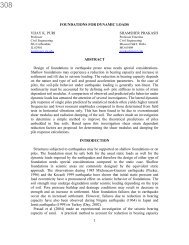
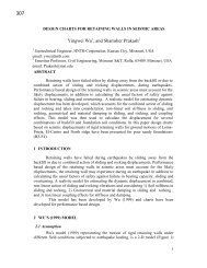
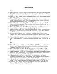
Report <strong>for</strong> Shamsher Prakash Foundation<strong>Swarm</strong> <strong>Robots</strong> <strong>for</strong> <strong>Autonomous</strong> Trash <strong>and</strong> <strong>Garbage</strong> <strong>Removal</strong>Pulkit GuptaSouvik RoyMarut ShuklaB.Tech 3 rd yearIndian Institute of Technology Roorkee
The “Hexagon” <strong>Swarm</strong> Robot during testingThe “Hexagon” <strong>and</strong> “Trapezium” robots
Table of Contents1. Abstract2. Introduction3. Key features4. Design <strong>and</strong> Working4.1 Mechanical Plat<strong>for</strong>m4.2 Electronic Hardware4.3 Software Design5. Simulations <strong>and</strong> Testing6. The Modular Design Concept7. Conclusion <strong>and</strong> Further Endeavour
AbstractA substantial amount of money is spent on manual labour in keepingcommon public places garbage free. The work is time consuming <strong>and</strong>requires constant vigilance. The problem can also be routinemaintenance of hygiene <strong>and</strong> sanitation in closed spaces. The workingconditions are unhygienic in certain cases <strong>and</strong> human interference isundesirable. The problem requires sustained group work <strong>and</strong>indefatigability on the part of the workers. Such a problem can besolved ingeniously by automation <strong>and</strong> swarm intelligence. Ourprototype swarm robots provide an effective solution <strong>for</strong> collectingr<strong>and</strong>omly scattered garbage <strong>and</strong> other waste matter <strong>and</strong> depositingthem to a common disposal area in an economic <strong>and</strong> efficient manner.The technique can be also be successfully employed in remote search<strong>and</strong> rescue operations, fast scanning of a given area <strong>for</strong> an object <strong>and</strong>autonomous collection of hazardous substances. The robot design issimple, robust, virtually maintenance free <strong>and</strong> cost effective. Themodular nature of our design makes it very versatile <strong>and</strong> it is able toper<strong>for</strong>m various kinds of tasks from garbage cleaning to search <strong>and</strong>rescue operations to exploration activities in the harshest of climates.
Introduction<strong>Swarm</strong> robotics is the study of how large number of relatively simple physicallyembodied agents can be designed such that a desired collective behavioremerges from the local interactions among agents <strong>and</strong> between the agents <strong>and</strong>the environment. It is a novel approach to the coordination of large numbers ofrobots. It is inspired from the observation of social insects ---ants, termites,wasps <strong>and</strong> bees--- which st<strong>and</strong> as fascinating examples of how a large numberof simple individuals can interact to create collectively intelligent systems.Social insects are known to coordinate their actions to accomplish tasks that arebeyond the capabilities of a single individual: termites build large <strong>and</strong> complexmounds, army ants organize impressive <strong>for</strong>aging raids, <strong>and</strong> ants can collectivelycarry large preys. In a similar manner our swarm robots collectively scan acertain region <strong>for</strong> garbage <strong>and</strong> other waste matter <strong>and</strong> dispose them off in acoordinated fashion. The real time coordinates of all the robots aresimultaneously tracked using an overhead camera <strong>and</strong> then sent to a CentralProcessing Unit <strong>for</strong> the execution of maze navigation <strong>and</strong> obstacle avoidancealgorithms. They are wirelessly sent comm<strong>and</strong>s by the CPU <strong>for</strong> locomotion <strong>and</strong>garbage collection. On-board sensors on the robot grippers identify garbage <strong>and</strong>hence collect them. Due to a presence of a number of robots redundant <strong>and</strong>repetitive scanning of the region is minimized <strong>and</strong> it reduces time takensignificantly. The concept can be successfully implemented <strong>and</strong> manual ef<strong>for</strong>t<strong>for</strong> such tasks can be eliminated.
KEY FEATURES1. A powerful <strong>and</strong> size efficient electrical board: The main design goal on theelectrical system’s printed circuit board (PCB) is to support all the functionalityrequired by the project while maintaining the required small size of the robots.The board is an Atmega 32 based development board that supports 3 analoginputs, 1 serial port, a wireless module, 8 digital I/O ports, a 7-segment LED, 4PWM generators, <strong>and</strong> a JTAG programming header.2. Wireless communication mechanism between agents: A mechanism mustbe provided <strong>for</strong> the agents to communicate among with each other throughwireless messages. This will allow flexibility <strong>and</strong> abstraction of computingpower to an external computer machine <strong>and</strong> allows the agents to focus only onexecuting behaviors rather than computing locally what to do next. Thispromotes loose coupling behaviors <strong>and</strong> dynamic programming.3. Visual recognition algorithms <strong>for</strong> the agent location, identity <strong>and</strong> facingdirection: Algorithms to analyze pictures taken from a top view camera to anarea were the agents are present are necessary. Such technique provides realtimetracking of robot location, identity, <strong>and</strong> facing direction.4. <strong>Autonomous</strong> navigation from visual recognition feedback <strong>and</strong> wirelesscommunication: Each robot will be provided limited visual in<strong>for</strong>mationwirelessly from top-view camera <strong>for</strong> on-board processing. Each robot will usethis in<strong>for</strong>mation, along with other on-robot sensors, to navigate around the robotworld, trying to determine her relative location, to obtain her direction ofmotion, <strong>and</strong> to ascertain her next movement.5. <strong>Autonomous</strong> surrounding awareness from visual feedback <strong>and</strong> wirelesscommunication: By querying the visual algorithms, a robot will find theposition of obstacles <strong>and</strong> other agents, with respect to its position, <strong>and</strong> willautonomously determine her next action.6. <strong>Autonomous</strong> artificial intelligence tasks executions system: An agent mustbe able to complete a given task. The task is described as two sets, one set ofrules <strong>and</strong> one of goals. Each rule can tell the robot to match location withobjects or to behave in a certain manner. The reaching of a goal will signal thecompletion of the task. By integrating the visual algorithms <strong>and</strong> a task, thesystem can interact with the robot autonomously <strong>and</strong> tell her when the goal isachieved <strong>and</strong> also provide other feedback that could help the agent to completethe task.
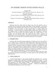
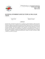
MECHANICAL PLATFORMRobot DesignRendered SolidWorks models of our swarm robot <strong>and</strong> the I-GripperMain ChassisThe chassis of each Robot is made of a 12 cm wide <strong>and</strong> 14 cm long Perspexframe. Perspex was chosen as material due to its low cost <strong>and</strong> the relative easeof machining. This frame serves as a building block <strong>for</strong> the entire structure ofthe robot. The chassis was machined to also support the motors <strong>and</strong> strategicallyaccommodate the battery pack with all the wiring in an elegant manner. Thedevelopment board has been mounted on a hinged plat<strong>for</strong>m keeping in mindease of working. Each robot has four 3” all-threaded rods, arranged in arectangular <strong>for</strong>mation <strong>and</strong> screwed into the chassis, serve as the supportingcolumns <strong>for</strong> the rest of the assembly.WheelsEach Robot rotates <strong>and</strong> translates by means of two motorized aluminium wheelsor radius of 7cm. The large wheel size with respect to the entire plat<strong>for</strong>m waschosen to achieve efficient rotation.GrippersThe I-GripperThe I-gripper is designed <strong>for</strong> objects with sharp edges <strong>and</strong> cubical shape. Thegripper consists of 2 movable plates mounted on a central support attached tothe bot. Planar motion can be imparted to the plates with the help of two motors.
The distance between the two plates can also be adjusted manually by movingtheir mounts along the slots inscribed in the central support to configure thegripper <strong>for</strong> different sized objects.The Robotic arm gripperThe robotic arm is powered by 4 (four) actuators- 1 pneumatic cylinder <strong>and</strong> 3DC motors. An electric signal from the microcontroller board activates asolenoid valve in the pneumatic actuator. An appropriate signal depending uponthe amount of rotation needed to the arm can actuate the pneumatic cylinder.The cylinder is connected off-axis to the arm so as to convert linear motion to arotary motion. Pneumatic cylinder offers the distinct advantage of higher torquecapability than an ordinary DC motor <strong>and</strong> helps us adhere to our corephilosophy of “cost effectiveness” in designing this system.Motors 1 <strong>and</strong> 2 impart rotary motion to the individual arm units depending uponthe amount of rotation required to reach the final end point.Motor 3 is the one that imparts the capability to grip an object. The motor shaftis connected to a flexible wires connected to individual finger on the h<strong>and</strong> of thearm. As these wires wind over the shaft of the motor, the fingers fold <strong>and</strong> gripthe object. A reverse motion of the motor causes the h<strong>and</strong> to release the object.
ELECTRONIC HARDWAREThe electrical system consists of compact printed circuitry boards that featureall the electronic system including a microprocessor <strong>and</strong> a wireless chip. Inaddition, various light emitting diodes (LEDs) as well as an optional LCD arestrategically mounted on the boards <strong>for</strong> debugging purposes.Power SupplyEach Robot features a 2-cell, 7.4V Lithium ion battery pack. Lithium ionchemistry batteries are preferable over other battery chemistries because of theirhigher energy density <strong>and</strong> lower cell count along with cheap <strong>and</strong> easyavailability.MicrocontrollerEach Robot’s top printed circuit board has an 8-bit ATmega 32,16MHzprocessor. This microcontroller processes of all the inputs <strong>and</strong> outputs,including creating the PWM motor driving signals. This ATmega32 was chosenbecause of its capabilities that lend themselves to easy implementation of sensor<strong>and</strong> control units. A JTAG programming port allows the hard-wireprogramming of the processor.Wireless CommunicationThe wireless communication between the central processing unit <strong>and</strong> each robotis facilitated by a Xbee 1 mW antenna wireless module which communicated
with another Xbee module attached to the CPU via a USB to serial converter.The XBee boards are mounted to each robot’s main (top) PCB.MotorsEach robot has two 12V 150RPM DC Metal Gear Motors. Low powerconsumption <strong>and</strong> excellent torque output make these motors extremely efficient<strong>for</strong> the purpose of our design.SOFTWARE DESIGNSOFTWARE SYSTEMSoftware ArchitectureThis project requires the design <strong>and</strong> implementation of three different softwaresystems, each using different programming languages, <strong>and</strong> a main system thatinterfaces them together. The first software system represents the behaviours<strong>and</strong> parameters that are programmed into the robot’s microprocessor. Thissystem represents the low-level software system of the project, is coded inembedded C, <strong>and</strong> targets the ATmega32 microprocessor’s architecture.The second software system provides all the computer vision algorithmsrequired. The vision functions are written using OpenCV, Intel’s open sourcecomputer vision library (http://intel.com/technology/computing/opencv/), <strong>and</strong> iswritten in C++. The design goal <strong>for</strong> this system is to provide a set of functionsthat optimize per<strong>for</strong>mance <strong>and</strong> per<strong>for</strong>m each of the desired tasks by using single
function calls. This complex function intentionally hides the implementation<strong>and</strong> details of its inner workings.The final <strong>and</strong> most crucial software system is the one in charge of integrating allthese systems, <strong>and</strong> synchronizing them to work together to create <strong>and</strong> passmessages between them. The final system design goals are to provide a simplegraphical user interface <strong>for</strong> a complex <strong>and</strong> well designed object-orientedsystem. This software system, written in C++, is responsible <strong>for</strong> h<strong>and</strong>ling all theartificial intelligence comm<strong>and</strong>s <strong>and</strong> behaviours. The project uses <strong>and</strong> integratesa multi-language plat<strong>for</strong>m software system, each one with independent goals,but targeted to work together. We can refer to the three systems as low-levelsystem (C), midlevel system (C++) <strong>and</strong> high-level system (again in C++).Low-Level System (LLS)The main goal of this system is to give the robots the ability to per<strong>for</strong>m differentbehaviours to allow interaction with the hardware (i.e., motors, LED’s etc.). TheLLS is designed with the goal of encapsulating each action into simple functioncalls, each of which will cause one <strong>and</strong> only one result in hardware. The robotmotion has been segregated into four sub classes: move<strong>for</strong>ward(), moveleft(),moveright(), stop() <strong>and</strong> moveback(). The hardware components that need to becontrolled are as follows.• Two Motor Controllers: These motor controllers provide independentmovement to the two wheels. Each wheel receives a high (1) or a low (0) value,corresponding to either an ON or an OFF state of the motor.• Digital I/0 ports: The ability to set <strong>for</strong> read or write up to eight distinct pins onthe I/O port headers permits additional hardware components to be added to thesystem. Some possible uses of these pins are <strong>for</strong> IR sensors (as inputs) or <strong>for</strong>LEDs (as outputs).• Serial Communication: The ability to communicate with another serial deviceis available. The exchange of data can be used <strong>for</strong> further intelligent behaviourIn addition to the hardware control provided above, the second goal is to createa wireless protocol to allow the robot to receive <strong>and</strong> send messages from theoutside world. A function has been created that h<strong>and</strong>les the incoming packetfrom the wireless receiver <strong>and</strong> trans<strong>for</strong>m its data into one of the comm<strong>and</strong>s thatare specified above. By integrating these actions, we can control the behaviourof the robot by simply sending the packets with the right data. In order <strong>for</strong> thisto work properly, we need to specify a consistent data packet that will tell therobot an appropriate series of actions.
Data Packet ProtocolEach <strong>and</strong> every robot has a set of four comm<strong>and</strong>s:Move <strong>for</strong>ward: Both Motors A <strong>and</strong> B are given a comm<strong>and</strong> to rotate <strong>for</strong>wardsMove backward: Both Motors A <strong>and</strong> B are given a comm<strong>and</strong> to rotatebackwardsMove left: The right motor B actuates while Motor A remains passiveMove right: The left motor A actuates while Motor B remains passive.Stop: No voltage is applied to either motorEach robot has a distinct 1 character code <strong>for</strong> each of these motions which isrecognized only by the microcontroller of that particular robot. The CPU sendsthese codes wirelessly through a Xigbee module. They are received by all therobots but accepted only by that robot whose comm<strong>and</strong> subset the code belongsto. In case of a large number of robots, the same set of codes can be used <strong>for</strong>each robot along with another code which first identifies the robot. Thecorresponding robot then receives the signal while other robots wait <strong>for</strong> theirrespective identification comm<strong>and</strong>s. For e.g. we used the comm<strong>and</strong> subset{W,X,A,D,S} <strong>and</strong> {T,B,F,H,G} <strong>for</strong> two robots.The agent's Xbee wireless module allows the robot to talk to the coordinatorXBee module, which uses the C++ code in the highlevel system. The Xbeemodules allow a two-way communication from the sender to a base boardplugged into the computer. The importance of wireless communication iscritical since it allows total control of the robot movement <strong>and</strong> data from anoutside computer, which of course can have orders of magnitude of highercapabilities than the embedded microcontrollers on the robots.Computer Vision System’s Mid-Level System (MLS)The main goal of the second software system, the MLS, is to provide multiplecomputer vision functions to allow the high-level system to locate <strong>and</strong> organizeall the agents’ in<strong>for</strong>mation that is located within the area. Enables us to trackeach individual robot independently <strong>and</strong> provides its real time co-ordinates aswell its orientation relative to the captured frame.
• Frames are continuously acquired through an overhead 1.3 MP Microsoft Lifecam<strong>and</strong> transmitted through an USB cable to a computer.• Once obtained the frame is first subjected to noise reduction techniques <strong>and</strong>then the image is broken into the three primary color channels. Subsequently,binary thresholding is done <strong>for</strong> all the channels to find out the brightest singleexpanse of pixels to identify our robot’s top surface using an inbuilt functioncvFindContours().• Using another function cvApproxPoly() , the bright contour is approximated asa polygon. Depending upon the number of sides <strong>and</strong> area constraints, theidentity of the robot is known. The function cvContourMoments() gives us thecentroid of each contour giving us the real time coordinates of each robot.• cvFindContours() also provides us with the vertex coordinates, so that thelength of each side can be calculated. The shortest side’s midpoint is found out<strong>and</strong> hence the direction vector of each robot is calculated.• To navigate the robot to a particular point the motors are wirelessly sentcomm<strong>and</strong>s to rotate the robot until the direction vector <strong>and</strong> the target vector,calculated using the target point <strong>and</strong> the robot countour centroid are aligned.The angle between the vectors is calculated <strong>for</strong> each frame. Once aligned, therobot is asked to move <strong>for</strong>ward until the contour’s centroid coincides with thetarget point. Once it reaches within a given threshold distance of the targetpoint, the robot stops.High-Level System (HLS)The high-level system is the most important component of the entire project.The HLS integrates the other two systems <strong>and</strong> orchestrates their interactions.Since there will be three agents running at the same time, this compiler runscode in a multithreaded fashion to guarantee the parallel running of the code.The main design goal <strong>for</strong> the HLS is to create a heavily object-oriented plat<strong>for</strong>mthat can be easily exp<strong>and</strong>ed while providing robustness, modularity <strong>and</strong>functionality. The HLS is divided into different subsystems <strong>and</strong> theirinteractions as shown in. The maze navigation <strong>and</strong> obstacle avoidancealgorithms are implemented in the HLS.The Navigation Algorithm The region is first segregated into a grid which is actually a 2-dimensional array created in the memory of the CPU. At any moment of
time, an element of the array can have three values: 0, 1 or 2. 0corresponds to an unexplored part of the grid, 1 corresponds to anexplored element of grid <strong>and</strong> 2 corresponds to a user defined obstacle. Initially all elements of the array are assigned 0 except the obstacleswhich are assigned 2 by the user. The default motion of the robot is to follow a spiral path <strong>for</strong> sweep ing thewhole grid, i.e. first the outermost elements( 2 rows <strong>and</strong> 2 columns) of thegrid are explored <strong>and</strong> then the adjacent elements(again 2 rows <strong>and</strong> 2columns) are explored At any given position of the robot, the next destination of the robot isfound out by the spiral algorithm, <strong>and</strong> all possible paths are found out toreach the next destination point. The paths are stored in a separate array in the <strong>for</strong>m of a set of coordinates<strong>and</strong> the shortest path is found out. The robot is then instructedto follow that path. Using real time feedback from the overhead camera, the present locationof the robot is tracked <strong>and</strong> it is guided to the destination point. Oncereached, the next destination point is found out.In this manner, whole ofthe region is explored while avoiding the obstacles.The collection algorithm While navigating through the region, if the onboard sensors of the robothappen to encounter any sort of trash or waste matter, the motion istemporarily stopped. The grippers close around the trash matter until the matter is well withinthe grip. Once secured, the robots ab<strong>and</strong>on their path <strong>and</strong> the navigationalgorithm stops <strong>and</strong> move the trash to a common base area whosecoordinates are user defined <strong>and</strong> known prior to the start of the algorithm. The grippers release the trash matter <strong>and</strong> the robot retracts back to whereit left the region. The algorithm is repeated if it finds another trash object until whole of theallotted region has been scanned.A typical path followed by a robot
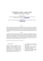
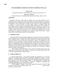
SIMULATIONS & TESTINGSimulation of the robotic arm gripper1. The six images showingthe proper orientation ofthe arm till the capturestage sequentially in arendered CAD simulation2. The two images showingthe two modes of therobotic palm3. The robotic arm in action
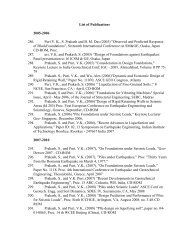
Testing of the vision <strong>and</strong> navigation algorithmsThe robustness <strong>and</strong> effectiveness of the vision based algorithms was testedsuccessfully. A single robot naviagated the entire grid with user definedobstacles successfully.A single wired robot executing the navigation algorithm during the initial testing phase.Red dots represent obstacles <strong>and</strong> blue dots represent the explored part of the maze.The wireless <strong>and</strong> the vision algorithms were tested using “Follow the leader” ast<strong>and</strong>ard algorithm in swarm robotics. Two different robots were used in thealgorithm. One was manually controlled wirelessly (“Trapezium”). The other(“Hexagon”) was made to follow it autonomously using real time feedbackcontrol from the camera <strong>and</strong> serial wireless communication to the robot. Somescreenshots from the actual video made during testing:
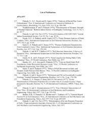
The Modular Design ConceptOur emphasis in this project has been on the application of swarm robotics to awide variety of fields. By integrating various modules with our current basicdesign we can use the collective swarm behaviour to solve a number ofproblems as the basic navigation algorithm using image processing remainssame. For example, instead of grippers we can have a vacuum suction onboardeach robot with cleans the surface as it scans the whole region. The gripperscan be disintegrated <strong>and</strong> the vacuum suction along with its circuitry can bemounted on the robot. This solution can also be used to search a particularobject in hostile terrain or maybe even water. Since we cannot have an overheadcamera in these situations, an onboard Global Positioning System (GPS) can beused to track the real time coordinates of the robots. Using their synchronizedsearch procedure <strong>and</strong> having a sufficiently large number of robots the terraincan be scanned in a very short time with desirable results. The locomotiondesign has also been kept modular. The basic motors remain the same. Using anumber of motors which only replicate the behaviour of the original twomotors, we can use any sort of locomotion technique. It may be a hexapod,continuous tracks or motorized paddles in case of water. The basic wheels canbe detached <strong>and</strong> the desired type of movement can be achieved by usingappropriate wheels. The algorithms remain the same <strong>and</strong> complex cases can beh<strong>and</strong>led by adding more functions to the existing program. The functions can bein the <strong>for</strong>m of noise filtering, obstacle detection or modified cases oflocomotion.The continuous track module
The GPS moduleThe vacuum suction pumpAll Terrain wheelLift arm assembly <strong>for</strong> heavier loads
Conclusion <strong>and</strong> Further EndeavourMultiple agent swarm robotics is the future when it comes to per<strong>for</strong>mingdaunting tasks efficiently in the least possible time with the minimum resourcespossible. The design presented here is a prototype swarm robotics plat<strong>for</strong>mcapable of per<strong>for</strong>ming virtually any kind of application sought of a robot in amuch more effective way by approaching the problem in a multi agentframework, especially keeping in mind the task of collecting r<strong>and</strong>omly scatteredgarbage over an area.This particular design offers the distinct advantage of being cost effective whichmakes it an af<strong>for</strong>dable choice <strong>for</strong> the masses. The design brings robotics to anordinary household. Modular nature of the design offers the advantage of beingused in a wide variety of applications wherein a user can install only the specificset of attachments over the skeleton to meet a particular requirement.This design has limitless opportunities <strong>for</strong> work in future. The basic skeletonhas been fabricated <strong>and</strong> rigorously tested. Now, any type of add-on or extensioncan be developed to meet any specific requirement. The modular design makesthe integration of these add-ons virtually seamless. By changing the design ofthe skeleton robot from wheeled locomotion to a boat propelled using the samemotors, we can make this design to per<strong>for</strong>m tasks in water bodies.By integrating adequate extension modules to the basic swarm robot structure,we can achieve very cost effective robotics solutions so flexible that they cancater to the daily needs of the masses <strong>and</strong> at the same time are possible ofper<strong>for</strong>ming sophisticated tasks in the most difficult working areas.