on seismic design of retaining walls - Shamsher Prakash Foundation
on seismic design of retaining walls - Shamsher Prakash Foundation
on seismic design of retaining walls - Shamsher Prakash Foundation

Create successful ePaper yourself
Turn your PDF publications into a flip-book with our unique Google optimized e-Paper software.
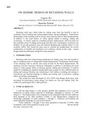
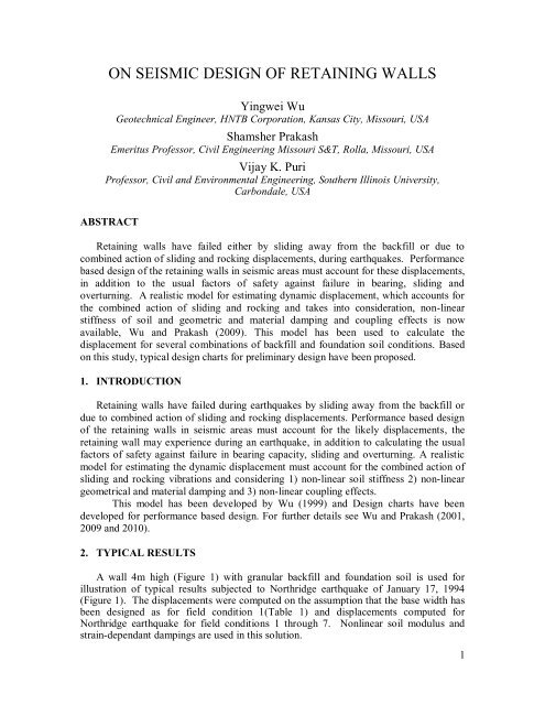
ON SEISMIC DESIGN OF RETAINING WALLSYingwei WuGeotechnical Engineer, HNTB Corporati<strong>on</strong>, Kansas City, Missouri, USA<strong>Shamsher</strong> <strong>Prakash</strong>Emeritus Pr<strong>of</strong>essor, Civil Engineering Missouri S&T, Rolla, Missouri, USAVijay K. PuriPr<strong>of</strong>essor, Civil and Envir<strong>on</strong>mental Engineering, Southern Illinois University,Carb<strong>on</strong>dale, USAABSTRACTRetaining <strong>walls</strong> have failed either by sliding away from the backfill or due tocombined acti<strong>on</strong> <strong>of</strong> sliding and rocking displacements, during earthquakes. Performancebased <strong>design</strong> <strong>of</strong> the <strong>retaining</strong> <strong>walls</strong> in <strong>seismic</strong> areas must account for these displacements,in additi<strong>on</strong> to the usual factors <strong>of</strong> safety against failure in bearing, sliding andoverturning. A realistic model for estimating dynamic displacement, which accounts forthe combined acti<strong>on</strong> <strong>of</strong> sliding and rocking and takes into c<strong>on</strong>siderati<strong>on</strong>, n<strong>on</strong>-linearstiffness <strong>of</strong> soil and geometric and material damping and coupling effects is nowavailable, Wu and <strong>Prakash</strong> (2009). This model has been used to calculate thedisplacement for several combinati<strong>on</strong>s <strong>of</strong> backfill and foundati<strong>on</strong> soil c<strong>on</strong>diti<strong>on</strong>s. Based<strong>on</strong> this study, typical <strong>design</strong> charts for preliminary <strong>design</strong> have been proposed.1. INTRODUCTIONRetaining <strong>walls</strong> have failed during earthquakes by sliding away from the backfill ordue to combined acti<strong>on</strong> <strong>of</strong> sliding and rocking displacements. Performance based <strong>design</strong><strong>of</strong> the <strong>retaining</strong> <strong>walls</strong> in <strong>seismic</strong> areas must account for the likely displacements, the<strong>retaining</strong> wall may experience during an earthquake, in additi<strong>on</strong> to calculating the usualfactors <strong>of</strong> safety against failure in bearing capacity, sliding and overturning. A realisticmodel for estimating the dynamic displacement must account for the combined acti<strong>on</strong> <strong>of</strong>sliding and rocking vibrati<strong>on</strong>s and c<strong>on</strong>sidering 1) n<strong>on</strong>-linear soil stiffness 2) n<strong>on</strong>-lineargeometrical and material damping and 3) n<strong>on</strong>-linear coupling effects.This model has been developed by Wu (1999) and Design charts have beendeveloped for performance based <strong>design</strong>. For further details see Wu and <strong>Prakash</strong> (2001,2009 and 2010).2. TYPICAL RESULTSA wall 4m high (Figure 1) with granular backfill and foundati<strong>on</strong> soil is used forillustrati<strong>on</strong> <strong>of</strong> typical results subjected to Northridge earthquake <strong>of</strong> January 17, 1994(Figure 1). The displacements were computed <strong>on</strong> the assumpti<strong>on</strong> that the base width hasbeen <strong>design</strong>ed as for field c<strong>on</strong>diti<strong>on</strong> 1(Table 1) and displacements computed forNorthridge earthquake for field c<strong>on</strong>diti<strong>on</strong>s 1 through 7. N<strong>on</strong>linear soil modulus andstrain-dependant dampings are used in this soluti<strong>on</strong>.1
3. SOIL AND WALL HEIGHTS USED TO DEVELOP DESIGN CHARTSWu (1999) has studied seven soil c<strong>on</strong>diti<strong>on</strong>s for foundati<strong>on</strong> soil F1-F7 and three soilsfor backfill B1-B3. Thus 21 combinati<strong>on</strong>s for foundati<strong>on</strong> and backfills soils wereinvestigated (Table 3). Rigid <strong>walls</strong> heights investigated are 4m, 5m, 6m, 7m, 8m, 9m,and 10m. Table 5 lists cumulative displacements for B3-F4.Table 3. Engineering properties for both foundati<strong>on</strong> soil and backfill (Wu, 1999)FOUNDATION SOIL (F)FSoilvoidcType kN/M 3 vdeg deg ratiokN/M 2 PI W%F-1 GW 21.07 37.5 25.0 0.25 0.3 - - 6F-2 GP 19.18 36.0 24.0 0.36 0.3 - - 6F-3 SW 18.00 35.0 23.3 0.46 0.3 - - 8F-4 SP 16.82 34.0 22.7 0.56 0.3 - - 10F-5 SM 15.70 33.0 22.0 0.68 0.3 - 4 15F-6 SC 14.00 30.0 20.0 0.88 0.3 - 13 25F-7 ML 14.15 32.0 21.3 0.85 0.3 9.57 4 14BACKFILL (B)BSoilvoidcW%Type kN/M 3 deg degvratiokN/M 2 PIB-1 GM 19.6 33.0 22.0 0.35 0.3 - - 10B-2 GP 18.9 34.0 22.7 0.40 0.3 - - 8B-3 SP 15.6 34.0 22.7 0.69 0.3 - - 8*All properties <strong>of</strong> backfill are for the c<strong>on</strong>diti<strong>on</strong> <strong>of</strong> 90 percent <strong>of</strong> the “Standard Proctor”.4. VERTICAL VS INCLINED WALLSIn order to ec<strong>on</strong>omize <strong>on</strong> <strong>design</strong> <strong>of</strong> <strong>walls</strong>, several cases <strong>of</strong> 6.0 m high <strong>retaining</strong> <strong>walls</strong>were analyzed for typical cases <strong>of</strong> foundati<strong>on</strong> soil c<strong>on</strong>diti<strong>on</strong> varying from well gradedgravel (GW) to silt (ML) and the backfill soil varying from silty gravel (GM) to poorlygraded sand (SP). Ground moti<strong>on</strong>s corresp<strong>on</strong>ding to El Centro, Loma Prieta and NorthRidge earthquakes were used in the analysis. Typical case <strong>of</strong> a reference <strong>retaining</strong> wall6.0 m high with nine different inclinati<strong>on</strong> angles <strong>of</strong> the wall face in c<strong>on</strong>tact with thebackfill „α‟ (0°, 1.25°, 2.5°, 3.75°, +5°, -1.25°, -2.5°, -3.75°, and -5°) subjected toNorthridge earthquake is used for illustrati<strong>on</strong>. The negative angle at the back <strong>of</strong> the wallis the case <strong>of</strong> the wall resting <strong>on</strong> the backfill. Figure 3 shows cumulative displacement<strong>of</strong> the <strong>retaining</strong> wall away from the backfill due to combined sliding and rocking effectsfor α = -5 ◦ , 0 ◦ and +5 ◦ for a base width <strong>of</strong> 3.57 m. The foundati<strong>on</strong> soil for this case waswell graded sand (SW) and the backfill c<strong>on</strong>sisted <strong>of</strong> submerged silt gravel (GM). It canbe observed from this figure that the negative values <strong>of</strong> „α‟ result in somewhat smallercumulative displacements compared to the case <strong>of</strong> vertical wall face (α = 0) or forpositive value <strong>of</strong> α within the range c<strong>on</strong>sidered Similar results were observed for othercases also. It, therefore, appears that <strong>retaining</strong> <strong>walls</strong> may be <strong>design</strong>ed for permissible4
displacement for sliding <strong>on</strong>ly and then be built resting by a few degrees <strong>on</strong> the backfill asexplained below. In this case this tilt is about 1.31° (Table 4).Fig: 3. Cumulative displacements <strong>of</strong> <strong>walls</strong> (B1-F3) with different inclinati<strong>on</strong>s withthe verticalTable 4.Cumulative displacement for several angles <strong>of</strong> inclinati<strong>on</strong> <strong>of</strong> the back <strong>of</strong> thewall subjected to Northridge earthquake c<strong>on</strong>diti<strong>on</strong> (B=3.57m).Cumulative Displacement by Fixed Base Width (3.57m)α angleBase width (m)Sliding RockingTotal(degree)Rocking (m)(m) (degree)(m)+5.00° 3.81 0.08 1.31 0.13 0.21+3.75° 3.76 0.08 1.30 0.13 0.21+2.50° 3.70 0.08 1.30 0.13 0.21+1.25° 3.63 0.08 1.29 0.13 0.210.00° 3.57 0.08 1.29 0.13 0.21-1.25° 3.50 0.08 1.28 0.13 0.21-2.50° 3.43 0.08 1.27 0.13 0.21-3.75° 3.35 0.08 1.26 0.13 0.21-5.00° 3.38 0.08 1.25 0.13 0.21Table 4 shows a summary <strong>of</strong> new base widths and computed displacement forvarious inclinati<strong>on</strong>s. The computed cumulative sliding, rocking and total displacementsare also shown in this table. The base widths decreased from 3.57m to 3.38m as theinclinati<strong>on</strong> changed from 0° to -5°, since the active earth forces decrease with negativeinclinati<strong>on</strong>. Therefore, the base width was somewhat smaller for a wall with a negative5
inclinati<strong>on</strong>. The angular rotati<strong>on</strong> in rocking (Table 4) decreased from 1.29° (α=0) to 1.25°(α=-5°), and the total displacements decreased slightly from 0.2155m to 0.2112m. Thecumulative displacements for these <strong>walls</strong> will not be significantly altered by changing theinclinati<strong>on</strong> at the back <strong>of</strong> the wall.For the wall built as a leaning-type rigid <strong>retaining</strong> wall with α = -5° lying <strong>on</strong> thebackfill, the wall experienced a rocking movement <strong>of</strong> 1.25° during the Northridgeearthquake. Therefore, when the wall was subjected to the same earthquake event up to 3or 4 times, the wall experienced a total rocking close to 5°. At this time, the wall maybecome vertical.Further analysis was c<strong>on</strong>ducted for 21 backfill and foundati<strong>on</strong> soil combinati<strong>on</strong>s fora typical reference wall 6m high, subjected to three earthquakes. The backfill soil wasvaried from silty gravel to poorly graded sand, and the foundati<strong>on</strong> soil varied from wellgraded gravel to silt <strong>of</strong> low compressibility.The results generally indicated that the <strong>design</strong> widths <strong>of</strong> foundati<strong>on</strong>s for 21 cases <strong>of</strong>backfill – foundati<strong>on</strong> soil combinati<strong>on</strong>s used in analysis generally reduced with values <strong>of</strong>α from 0° to -5°. This may result in saving <strong>of</strong> 8 -10 % in the material cost. It is, thereforerecommended that rigid <strong>walls</strong> be c<strong>on</strong>structed with the negative batter in the <strong>walls</strong> resting<strong>on</strong> the backfill. In this situati<strong>on</strong>, these can be <strong>design</strong>ed <strong>on</strong>ly for sliding displacements.5. RECOMMENDED DESIGN PROCEDURE1. Determine the secti<strong>on</strong> for static loading c<strong>on</strong>diti<strong>on</strong> with FOS=2.5 in bearing, andFOS= 1.5 for sliding and tilting as a rigid body and no tensi<strong>on</strong> <strong>on</strong> the heel.2. Estimate the sliding displacement from Wu (1999) <strong>design</strong> charts for comparablebackfill and foundati<strong>on</strong> soils and comparable ground moti<strong>on</strong>.3. Compare these displacements with permissible displacements as per Euro Code (300α max ).4. If displacement in step 2 is less than that in step 3, then <strong>design</strong>s is OK, otherwiserevise the secti<strong>on</strong>s <strong>of</strong> the wall for lower FOS in step 1.6. TYPICAL DESIGN CHARTSTable 5 lists the sliding and total displacement and rotati<strong>on</strong> <strong>of</strong> <strong>walls</strong> 4m-10m high andsubjected to 3-good moti<strong>on</strong>s <strong>of</strong> 1) El-Centro1946, 2) Northridge 1994, and 3) LomaPrieta 1979. Similar <strong>design</strong> charts for all 21 cases <strong>of</strong> table 3 have been prepared by Wu(1999)6
Table 5: Cumulative Displacements for Walls 4 to 10m High with B3-F4 and Field C<strong>on</strong>diti<strong>on</strong>s 1, 2and 7 (Table 2) subjected to El-Centro, Northridge and Loma-Prieta earthquakesCumulative DisplacementH andB 1(m)FieldC<strong>on</strong>.SlidingmEl-Centro 2 Northridge 2 Loma-Prieta 2Rockingdegree (m)TotalmSlidingmRockingdegree (m)TotalmSlidingmRockingdegree (m)Totalm1 0.0943 2.59 (0.1808) 0.2751 0.0642 1.67 (0.1164) 0.1806 0.0055 0.11 (0.0077) 0.01324(2.09)2 0.0987 2.75 (0.1922) 0.2909 0.0673 1.79 (0.1248) 0.1922 0.0059 0.12 (0.0083) 0.01427 0.1076 3.04 (0.2124) 0.3200 0.0739 1.99 (0.1386) 0.2125 0.0065 0.13 (0.0093) 0.01571 0.1113 2.74 (0.2395) 0.3509 0.0769 1.81 (0.1576) 0.2343 0.0073 0.13 (0.0116) 0.01895(2.51)2 0.1156 2.89 (0.2526) 0.3681 0.0802 1.92 (0.1673) 0.2475 0.0078 0.15 (0.0127) 0.02057 01256 3.20 (0.2760) 0.4046 0.0872 2.13 (0.1859) 0.2731 0.0086 0.16 (0.0142) 0.02281 0.1247 2.79 (0.2926) 0.4173 0.0868 1.87 (0.1955) 0.2823 0.0089 0.15 (0.0160) 0.02496(2.92)2 0.1289 2.92 (0.3063) 0.4352 0.0896 1.97 (0.2060) 0.2956 0.0096 0.17 (0.0173) 0.02697 0.1400 3.23 (0.3384) 0.4784 0.0977 2.18 (0.2283) 0.3260 0.0106 0.19 (0.0195) 0.03011 0.1359 2.78 (0.3398) 0.4757 0.0948 1.88 (0.2299) 0.3247 0.0106 0.17 (0.0205) 0.03117(3.35)2 0.1399 2.90 (0.3540) 0.4939 0.0987 1.97 (0.2403) 0.3390 0.0114 0.18 (0.0221) 0.03357 0.1519 3.20 (0.3911) 0.5430 0.1073 2.18 (0.2668) 0.3741 0.0215 0.20 (0.0248) 0.03731 0.1457 2.74 (0.3823) 0.5280 0.1025 1.87 (0.2606) 0.3631 0.0124 0.18 (0.0250) 0.03748(3.77)2 0.1500 2.84 (0.3970) 0.5471 0.1051 1.95 (0.2720) 0.3771 0.0131 0.19 (0.0270) 0.04017 0.1628 3.14 (0.4390) 0.6018 0.1144 2.16 (0.3015) 0.4159 0.0147 0.22 (0.0303) 0.04491 0.1544 2.68 (0.4209) 0.5754 0.1083 1.84 (0.2886) 0.3969 0.0140 0.19 (0.0296) 0.04369(4.19)2 0.1584 2.77 (0.4356) 0.5941 0.1108 1.91 (0.3001) 0.4109 0.0147 0.20 (0.0319) 0.04667 0.1718 3.07 (0.4817) 0.6536 0.1203 2.12 (0.3327) 0.4259 0.0160 0.23 (0.0358) 0.05191 0.1608 2.53 (0.4411) 0.6017 0.1123 1.74 (0.3033) 0.4156 0.0151 0.19 (0.0326) 0.047710(4.72)2 0.1648 2.61 (0.4559) 0.6207 0.1153 1.80 (0.3144) 0.4297 0.0157 0.20 (0.0350) 0.05077 0.1785 2.89 (0.5039) 0.6825 0.1250 2.00 (0.3484) 0.4734 0.0172 0.22 (0.0392) 0.05641 H: height <strong>of</strong> wall, B: base width2 Permissible displacements for three earthquakes according to Eurocode = 300 α maxEl-Centro = 300*0.349 (mm) = 0.1047mNorthridge = 300*0.344 (mm) = 0.1032mLoma-Prieta = 300*0.113 (mm) = 0.0339m7
7. CONCLUSIONSThe following c<strong>on</strong>clusi<strong>on</strong>s are drawn:1. A realistic displacement model for rigid <strong>retaining</strong> <strong>walls</strong> under earthquake c<strong>on</strong>diti<strong>on</strong>has been developed.2. This model c<strong>on</strong>siders n<strong>on</strong>-linear soil properties and any water c<strong>on</strong>diti<strong>on</strong> behind thewall (Wu 1999).3. Design charts for wall heights 4m-10m and 21 backfill foundati<strong>on</strong> soils have beendeveloped for use in preliminary <strong>design</strong>.8. ACKNOWLEDGEMENTThe manuscript was typed by Khushboo Lall and Reformatted by Raghu Mutnuri, withgreat care.9. REFERENCESEUROCODE 8 (EUROPEAN PRESTANDARD 1994). "Design Provisi<strong>on</strong>s forEarthquake Resistance <strong>of</strong> Structures- Part 5: Foundati<strong>on</strong>s, Retaining Structures andGeotechnical Aspects", The Commissi<strong>on</strong> <strong>of</strong> the European Communities.Wu, Y. (1999). "Displacement-Based Analysis and Design <strong>of</strong> Rigid Retaining Wallsduring Earthquakes", Ph.D. Dissertati<strong>on</strong>, Univ. <strong>of</strong> Missouri-Rolla.Wu, Y. and <strong>Prakash</strong>, S. (2001). "Seismic Displacements <strong>of</strong> Rigid Retaining Walls-state <strong>of</strong>the art"paper number 705, Proceedings Fourth Intrn C<strong>on</strong>f Recent Adv in Geot Eq Engand Soil Dynamics CD ROM, San Diego, MarchWu, Y. and <strong>Prakash</strong>, S. (2009). “Design <strong>of</strong> Retaining <strong>walls</strong> in Seismic Areas “IS Tokyo2009”. Paper No 149, Internati<strong>on</strong>al c<strong>on</strong>ference <strong>on</strong> Performance based Design in GeoEarthquake Engineering (CD-ROM).Wu, Y. and <strong>Prakash</strong>, S. (2010). “Design Charts for Retaining Walls in Seismic Areas”.Paper No 178 , ASCE C<strong>on</strong>ference . Geo-FL. (CD, ROM).8