Download Product Data Sheet - PJ Boner
Download Product Data Sheet - PJ Boner
Download Product Data Sheet - PJ Boner

Create successful ePaper yourself
Turn your PDF publications into a flip-book with our unique Google optimized e-Paper software.
BATCH CONTROLLER<br />
WITH TWO STAGE CONTROL / PULSE AND<br />
ANALOG OUTPUT IN RELATION TO THE FLOW RATE<br />
DATASHEET F131 - BATCH CONTROLLER<br />
Features<br />
• Large display shows preset value, running<br />
batch value and instantaneous flow rate.<br />
• Self-learning overrun correction.<br />
• Easy operation to enter a batch value and to<br />
control the process.<br />
• Count-up and count-down function available.<br />
• Selectable on-screen engineering units;<br />
volumetric or mass.<br />
• Ability to process all types of flowmeter<br />
signals.<br />
• Operational temperature -30°C up to +80°C<br />
(-22°F up to 178°F).<br />
• Very compact design for panel mount, wall<br />
mount or field mount applications.<br />
• Rugged aluminum field mount enclosure<br />
IP67/NEMA4X.<br />
• Intrinsically Safe<br />
II 1 GD EEx ia IIB/IIC T4 T100°C.<br />
• Explosion/flame proof II 2 GD EEx d IIB T5.<br />
• Full Modbus communication RS232/485/TTL.<br />
• Loop or battery powered, 8 - 24V AC/DC or<br />
115 - 230V AC power supply.<br />
• Sensor supply 3.2 / 8.2 / 12 / 24V DC.<br />
1<br />
Signal output<br />
• Two configurable control outputs: for<br />
two-stage or one-stage control.<br />
• (0)4 - 20mA / 0 - 10V DC according to flow rate.<br />
• Scaled pulse output according to acc. total.<br />
Signal input<br />
Flow<br />
• Reed-switch.<br />
• NAMUR.<br />
• NPN/PNP pulse.<br />
• Sine wave (coil).<br />
• Active pulse signals.<br />
• (0)4 - 20mA.<br />
• 0 - 10V DC.<br />
Status<br />
• Remote control: start.<br />
• Remote control: pause / stop.<br />
Applications<br />
• For batching small up to very large quantities.<br />
Flow rate indication and / or retransmission is<br />
required. Alternative basic model: F030 and<br />
F130 or more sophisticated models: F136 and<br />
300 series.
General information<br />
Introduction<br />
The F131 offers in addition to the standard<br />
functions an analog output signal in relation to<br />
the flow rate. The operator can enter a batch<br />
quantity easily or execute repeating batches.<br />
During the batch, the preset value is displayed<br />
as well as the batched (or remaining) quantity<br />
and the flow rate. The automatic self-learing<br />
overrun correction will ensure an accurat result<br />
each batch again. A wide selection of options<br />
further enhance this models capabilities.<br />
Display<br />
The display has large 17mm (0.67”) and 8mm<br />
(0.31”) digits. Besides the proces information,<br />
a seven digit resettable "day total" is available<br />
as well as an eleven digit non-resettable<br />
accumulated total. All are backed-up in<br />
EEPROM memory every minute.<br />
Configuration<br />
All configuration settings are accessed via a<br />
simple operator menu which can be pass-code<br />
protected. Each setting is clearly indicated with<br />
an alphanumerical description, therefore<br />
avoiding confusing abbreviations and baffling<br />
codes. All settings are safely stored in EEPROM<br />
memory in the event of sudden power failure.<br />
Analog output signal<br />
The flow rate is re-transmitted with the<br />
(0)4 - 20mA or 0 - 10V DC output signal.<br />
The output signal is updated ten times per<br />
second with a filter function being available to<br />
smoothen out the signal if desired.<br />
The output value is user defined in relation to<br />
the flow rate, e.g. 4mA equals to 15L/Hr and<br />
20mA equals to 2000L/Hr. The output signal can<br />
be passive, active or isolated where the passive<br />
output type will loop power the F131 as well.<br />
Control outputs<br />
Two outputs are available which can be<br />
configured to operate as two stage control for<br />
large batch quantities or one stage control for<br />
smaller batches, where the second output is<br />
available as a scaled pulse output.<br />
The maximum output frequency is 64Hz.<br />
The output signals can be a passive NPN, active<br />
PNP or an isolated electro-mechanical relay.<br />
Signal input<br />
The F131 will accept most pulse and analog<br />
input signals for flow or mass flow<br />
measurement. The input signal type can be<br />
selected by the user in the configuration menu<br />
without having to adjust any sensitive<br />
mechanical dip-switches or jumpers.<br />
Communication<br />
All process data and settings can be read and<br />
modified manually or through the Modbus<br />
communication link (RS232 / RS485). If desired,<br />
the batch process can even be started and<br />
stopped through communication.<br />
Full Modbus functionality remains available for<br />
the Intrinsically Safe version (TTL).<br />
Hazardous areas<br />
For hazardous area applications, this model has<br />
been ATEX certified Intrinsically Safe II 1<br />
GD EEx ia IIB / IIC T4 T100°C with an allowed<br />
operational temperature of -30°C to +70°C<br />
(-22°F to +158°F). A flame proof enclosure is also<br />
available with the rating II 2 GD EEx d IIB T5.<br />
Enclosures<br />
Various types of enclosures can be selected, all<br />
ATEX approved. As standard the F131 is<br />
supplied in an GRP panel mount enclosure,<br />
which can be converted to an GRP field mount<br />
enclosure. Most popular is our rugged<br />
aluminum field mount enclosure with IP67 /<br />
NEMA 4X rating. Both European or U.S. cable<br />
gland entry threads are available.<br />
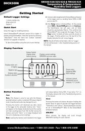
Overview application F131<br />
Pulse output R2<br />
(with 1-stage control only)<br />
Control output R1<br />
Analog output<br />
Flowmeter<br />
input<br />
Communication link<br />
External START<br />
External PAUSE / STOP<br />
Control output R2<br />
2<br />
F131
I<br />
+<br />
+<br />
I<br />
I<br />
31 mm<br />
(1.22")<br />
29 mm<br />
(1.14")<br />
120 mm (4.72")<br />
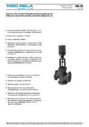
Dimensions enclosures<br />
Aluminum & GRP panel mount enclosure<br />
130 mm (5.12")<br />
HB & HC enclosures<br />
130 mm (5.12")<br />
115 (4.53")<br />
Aluminum & GRP field / wall mount enclosures<br />
98 (3.86")<br />
panel cut-out<br />
Ø 7mm (0.27") Ø 7mm (0.27")<br />
Terminal connections<br />
COMMUNICATION / BACKLIGHT<br />
20 21 22 23 24 25 26 27 28 29 30 31<br />
CB: RS232<br />
RXD TXD<br />
DTR<br />
+12V<br />
CH: RS485 - 2 wire<br />
A B<br />
CI: RS485 - 4 wire<br />
Y Z<br />
A B<br />
CT: TTL Intrinsically Safe<br />
RXD TXD<br />
DTR<br />
+12V<br />
ZB: Backlight option<br />
+<br />
120 mm (4.72")<br />
+ +<br />
18 19<br />
(With PD / PF / PM terminals 26 / 31 are not available,<br />
backlight power supply is integrated.)<br />
60 mm (2.36")<br />
75 mm (2.95")<br />
112 mm (4.40")<br />
17<br />
Aluminum<br />
30mm 30mm<br />
22,50mm<br />
HA<br />
HD<br />
GRP<br />
STOP INPUT<br />
15 16<br />
STOP<br />
+<br />
PG9 M20 x 1,5 PG9<br />
30mm 30mm<br />
22,50mm<br />
HM<br />
HE<br />
30mm 30mm<br />
22,50mm<br />
START INPUT<br />
12 13 14<br />
START<br />
+<br />
M16 x 1,5 M20 x 1,5 M16 x 1,5<br />
22,50mm<br />
HN<br />
HF<br />
Ø16<br />
Ø20<br />
Ø16<br />
22,50mm (0.9")<br />
FLOWMETER INPUT<br />
9 10 11<br />
P: coil<br />
P: reed switch / NPN<br />
+<br />
P: PNP<br />
- +<br />
P: namur<br />
- +<br />
P: active signal<br />
+<br />
A: (0)4 - 20mA<br />
I+ +<br />
U: 0 - 10V<br />
+<br />
U+<br />
A - PL: 4 - 20mA<br />
I +<br />
25mm<br />
M20 x 1,5<br />
25mm<br />
M20 x 1,5 M20 x 1,5<br />
12mm 12mm<br />
24mm 24mm<br />
36mm 36mm<br />
1 /2"NPT<br />
6 x M12<br />
22,50mm<br />
14mm 17mm<br />
0.9"<br />
HO<br />
HP<br />
HT<br />
HG<br />
HH<br />
HJ<br />
Ø22 ( 7 / 8")<br />
25mm 25mm<br />
Ø20 Ø20<br />
12mm 12mm<br />
24mm 24mm<br />
36mm 36mm<br />
Ø12<br />
30mm (1.18") 30mm (1.18")<br />
Ø22 ( 7 / 8") Ø22 ( 7 / 8") Ø22 ( 7 / 8")<br />
22,50mm<br />
14mm 17mm<br />
22,50mm (0.9")<br />
ANALOG OUTPUT<br />
CONTROL<br />
OUTPUT R1<br />
CONTROL / PULSE<br />
OUTPUT R2<br />
POWER SUPPLY<br />
OPTIONAL<br />
GND 1 2 3 4 5 6 7 8<br />
PD: 8 - 24V AC<br />
OA: active 24V DC OA: active 24V DC AA: 4 - 20mA<br />
I+<br />
PD: 8 - 24V DC<br />
OT: passive trans. OT: passive trans. AB: 0 - 20mA<br />
I+<br />
- +<br />
+<br />
+<br />
PD - XI: 16 - 30V DC OR: mech. relay OR: mech. relay AF: 4 - 20mA<br />
- + + = = = = I- I+<br />
PF: 24V AC<br />
AI: 4 - 20mA<br />
I- I+<br />
AP: 4 - 20mA<br />
I+<br />
PF: 24V DC<br />
- +<br />
PM: 115 - 230V AC<br />
AU: 0 - 10V<br />
U U+<br />
PX: 8 - 30V DC<br />
Output loop powered unit with type AP<br />
(terminals GND - 1 - 2 are not available)<br />
PB / PC: battery powered<br />
Internal long life Lithium battery<br />
(terminals GND - 1 - 2 are not available)<br />
PL: input loop powered<br />
(terminals GND - 1 - 2 are not available)<br />
1.18" 1.18"<br />
0.9"<br />
HU<br />
HK<br />
Display example - 90 x 40mm (3.5” x 1.6”)<br />
1 /2"NPT 1 /2"NPT 1 /2"NPT<br />
Flat bottom, no holes available.<br />
15mm<br />
15mm<br />
16mm 15mm<br />
HV<br />
38mm<br />
4 x M20 x 1.5<br />
HZ<br />
F131 3
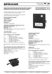
Typical wiring diagram F131-P-(AP)-CH-OT-PB<br />
Typical wiring diagram F131-P-AP-CH-OT-PX<br />
TERMINAL CONNECTORS<br />
F100-series<br />
BATTERY POWERED<br />
TERMINAL CONNECTORS<br />
F100-series<br />
OUTPUT LOOP POWERED<br />
Modbus communication type CH: RS485 - 2 wire<br />
Modbus communication type CH: RS485 - 2 wire<br />
B<br />
A<br />
Common ground<br />
26 28 29<br />
B<br />
A<br />
Common ground<br />
26 27 28 29<br />
+ 3.2V 1M<br />
low-pass<br />
filter<br />
Common ground<br />
+ 3.2V 1M<br />
low-pass<br />
filter<br />
Common ground<br />
12 13 14 15 16<br />
Logic input:<br />
PAUSE / STOP<br />
Logic input:<br />
START<br />
+ 3.2V 1M<br />
low-pass<br />
filter<br />
Common ground<br />
+ 3.2V 1M<br />
low-pass<br />
filter<br />
Common ground<br />
12 13 14 15 16<br />
Logic input:<br />
PAUSE / STOP<br />
Logic input:<br />
START<br />
Circuit depends on<br />
type of signal<br />
Supply *<br />
Signal<br />
Common ground<br />
9 10 11<br />
Flowmeter input<br />
type: P<br />
pulse<br />
Circuit depends on<br />
type of signal<br />
Supply *<br />
Signal<br />
Common ground<br />
9 10 11<br />
Flowmeter input<br />
type: P<br />
pulse<br />
Analog output type AP: passive 4 - 20mA (loop powered)<br />
Common ground<br />
7 8<br />
Analog output type AP:<br />
(not used in this example)<br />
e.g. relay or solenoid<br />
Common ground<br />
7 8<br />
e.g. indicator<br />
e.g. relay or solenoid<br />
+<br />
8 - 30V DC<br />
+<br />
-<br />
Common ground<br />
4 5 6<br />
Control or pulse output type OT:<br />
passive transistor<br />
123456<br />
e.g. counter<br />
8 - 24V DC<br />
-<br />
Common ground<br />
4 5 6<br />
Control or pulse output type OT:<br />
passive transistor<br />
Common ground<br />
3<br />
Please note: AP may be used<br />
in combination with the<br />
battery!<br />
Common ground<br />
3<br />
e.g. relay or solenoid<br />
AP will power the unit<br />
(output loop powered);<br />
the battery will be disabled<br />
automatically untill power<br />
is disconnected).<br />
*Supply voltage: 1.2 / 3.2V DC to sensor<br />
*Supply voltage: 1.2 / 3.2V DC to sensor<br />
4<br />
F131
Typical wiring diagram F131-A-AA-CB-OA-PD<br />
Typical wiring diagram F131-A-AI-CI-OR-PM<br />
TERMINAL CONNECTORS<br />
F100-series<br />
24V AC / DC POWER SUPPLY<br />
TERMINAL CONNECTORS<br />
F100-series<br />
115 - 230V AC POWER SUPPLY<br />
TXD<br />
RXD<br />
DTR<br />
12V<br />
Common ground<br />
26 27 28 29<br />
Modbus communication type CB: RS232<br />
Z<br />
Y<br />
B<br />
A<br />
Common ground<br />
28 29 30 31<br />
26<br />
Modbus communication type CI: RS485 - 4 wire<br />
+ 3.2V 1M<br />
low-pass<br />
filter<br />
Common ground<br />
15 16<br />
Logic input:<br />
PAUSE / STOP<br />
+ 3.2V 1M<br />
low-pass<br />
filter<br />
Common ground<br />
15 16<br />
Logic input:<br />
PAUSE / STOP<br />
+ 3.2V 1M<br />
low-pass<br />
filter<br />
Common ground<br />
Supply *<br />
Signal<br />
Common ground<br />
+<br />
-<br />
Common ground<br />
+<br />
-<br />
Common ground<br />
+<br />
-<br />
Common ground<br />
Main supply<br />
Common ground<br />
0 1 2 3 4 5 6 7 8 9 10 11 12 13<br />
e.g. indicator<br />
e.g. relay<br />
123456<br />
e.g. counter<br />
Power supply type PD:<br />
8 - 24V AC / DC<br />
Logic input:<br />
START<br />
Flowmeter input type A:<br />
(0)4 - 20mA<br />
Analog output type AA:<br />
active 4 - 20mA<br />
Control output type OA:<br />
active 24V DC pulse<br />
Control or pulse output type OA:<br />
active 24V DC pulse<br />
8 - 24V AC<br />
+<br />
8 - 24V DC<br />
-<br />
Earth<br />
+ 3.2V 1M<br />
low-pass<br />
filter<br />
Common ground<br />
Supply *<br />
Signal<br />
Common ground<br />
Main supply<br />
Common ground<br />
12 13<br />
0 1 2 7 8 9 10 11<br />
6<br />
5<br />
4<br />
3<br />
Logic input:<br />
START<br />
Flowmeter input type A:<br />
(0)4 - 20mA<br />
e.g. indicator<br />
e.g. relay or solenoid<br />
e.g. relay or solenoid<br />
Power supply type PM:<br />
115 - 230V AC<br />
Analog output type AI:<br />
passive isolated 4 - 20mA<br />
+<br />
8 - 30V DC<br />
-<br />
Control or pulse output<br />
type OR:<br />
mechanic relay<br />
L1<br />
N<br />
Earth<br />
*Supply voltage: 3.2 / 8.2 / 12 / 24V DC to sensor<br />
*Supply voltage: 3.2 / 8.2 / 12 / 24V DC to sensor<br />
F131 5
Hazardous area applications<br />
The F131-XI has been ATEX approved by<br />
KEMA for use in Intrinsically Safe<br />
applications. It is approved according to<br />
II 1 GD EEx ia IIB/IIC T4 T100°C for gas<br />
and dust applications with an operational<br />
temperature range of -30°C to +70°C<br />
(-22°F to +158°F). Besides the I.S. power<br />
supplies for the control outputs, it is allowed<br />
to connect up to three I.S. power supplies in<br />
IIB applications or one in IIC applications.<br />
Full functionality of the F131 remains<br />
available, including two stage control,<br />
4 - 20mA output, pulse output and Modbus<br />
communication (type CT). Power supply type<br />
PD-XI offers a 8.2V sensor supply e.g. for one<br />
Namur sensor. A flame proof enclosure with<br />
rating ATEX II 2 GD EEx d IIB T5 is<br />
available as well. Please contact your supplier<br />
for further details.<br />
Certificate of conformity KEMA 03ATEX1074 X<br />
Configuration example IIB and IIC<br />
F131-P-(AP)-(CT)-OT-PC-(PX)-XI - Battery powered unit<br />
+ 3.2V 1M<br />
low-pass<br />
filter<br />
Common ground<br />
+ 3.2V 1M<br />
low-pass<br />
filter<br />
Common ground<br />
16<br />
15<br />
12 13<br />
Modbus communication type CT: TTL (not used in this example).<br />
Ci is negligibly<br />
small<br />
Ci is negligibly<br />
small<br />
Logic input:<br />
PAUSE / STOP<br />
Logic input:<br />
START<br />
HAZARDOUS AREA<br />
SAFE AREA<br />
Circuit depends on<br />
type of signal<br />
Supply *<br />
Signal<br />
Common ground<br />
Common ground<br />
Common ground<br />
Common ground<br />
3 4 5 6 7 8 9 10 11<br />
Ci is negligibly<br />
small<br />
Analog output type AP:<br />
passive 4 - 20mA<br />
(not used in this example).<br />
Ci is negligibly<br />
small<br />
Ci is negligibly<br />
small<br />
* Note sensor supply voltage: 1.2V DC for coil sensors or 3.2V DC for other pulse sensors.<br />
Flowmeter input<br />
type: P<br />
pulse<br />
Please note: type AP may be used in combination<br />
with the battery (type PC), but only in IIB applications!<br />
AP will loop power the unit; the battery will be disabled<br />
automatically till power is disconnected.<br />
e.g. relay<br />
Control output type OT: passive transistor<br />
e.g. relay<br />
Control or pulse output type OT: passive transistor<br />
-<br />
+<br />
-<br />
+<br />
Uo=max 30V<br />
Io=max 100mA<br />
Po=max 750mW<br />
POWER SUPPLY<br />
e.g. MTL 5025<br />
or<br />
SWITCH INTERFACE<br />
e.g. MTL 5011B<br />
e.g. relay<br />
Uo=max 30V<br />
POWER SUPPLY<br />
e.g. MTL 5025<br />
Io=max 100mA<br />
or<br />
Po=max 750mW<br />
SWITCH INTERFACE<br />
e.g. MTL 5011B e.g. relay<br />
Note: above values are safety values.<br />
Consult the technical specification for operational values.<br />
6<br />
F131
Configuration example IIB and IIC - F131-P-AP-(CT)-OT-PX-XI - Output loop powered<br />
TERMINAL CONNECTORS<br />
F100 - series<br />
HAZARDOUS AREA<br />
SAFE AREA<br />
TXD<br />
RXD<br />
DTR<br />
+12V<br />
Common ground<br />
26 27 28 29<br />
Modbus communication type CT: TTL<br />
Please note: communciation type CT is not allowed in IIC applications.<br />
+<br />
-<br />
ISOLATOR:<br />
Uo=max 30V I.S. Certified Isolator<br />
TTL to<br />
Io=max 250mA<br />
RS232 / RS422 / TTL<br />
Po=max 850mW<br />
For example: MTL5051<br />
<br />
e.g. PC<br />
+ 3.2V 1M<br />
low-pass<br />
filter<br />
Common ground<br />
16<br />
15<br />
Ci is negligibly<br />
small<br />
Logic input:<br />
PAUSE / STOP<br />
+ 3.2V 1M<br />
low-pass<br />
filter<br />
Common ground<br />
12 13 14<br />
Ci is negligibly<br />
small<br />
Logic input:<br />
START<br />
Circuit depends on<br />
type of signal<br />
Supply *<br />
Signal<br />
Common ground<br />
Common ground<br />
Common ground<br />
Common ground<br />
3 4 5 6 7 8 9 10 11<br />
Ci is negligibly<br />
small<br />
Ci is negligibly<br />
small<br />
Ci is negligibly<br />
small<br />
Analog output type AP:<br />
passive 4 - 20mA (output loop powered)<br />
Control output type OT:<br />
passive transistor<br />
Control output type OT:<br />
passive transistor<br />
Flowmeter input<br />
type: P<br />
pulse<br />
e.g. indicator<br />
e.g. relay<br />
e.g. relay or counter<br />
-<br />
+<br />
-<br />
+<br />
-<br />
+<br />
Uo=max 30V<br />
Io=max 100mA<br />
Po=max 750mW<br />
Uo=max 30V<br />
Io=max 100mA<br />
Po=max 750mW<br />
POWER SUPPLY<br />
e.g. MTL 5025<br />
and / or<br />
REPEATER<br />
e.g. MTL 5042<br />
POWER SUPPLY<br />
e.g. MTL 5025<br />
or<br />
SWITCH INTERFACE<br />
e.g. MTL 5011B<br />
e.g. indicator<br />
e.g. relay<br />
Uo=max 30V<br />
POWER SUPPLY<br />
e.g. MTL 5025<br />
Io=max 100mA<br />
or<br />
Po=max 750mW<br />
SWITCH INTERFACE<br />
e.g. MTL 5011B e.g. counter<br />
Note: above values are safety values.<br />
Consult the technical specification for operational values.<br />
* Note sensor supply voltage: 1.2V DC for coil sensors or 3.2V DC for other pulse sensors.<br />
F131 7
Configuration example IIB and IIC - F131-A-AF-(CT)-OT-PD-XI - Power supply 16 - 30V DC<br />
TERMINAL CONNECTORS<br />
F100 - series<br />
HAZARDOUS AREA<br />
SAFE AREA<br />
TXD<br />
RXD<br />
DTR<br />
+12V<br />
Common ground<br />
26 27 28 29<br />
Modbus communication type CT: TTL<br />
Please note: communciation type CT is not allowed in IIC applications.<br />
+<br />
-<br />
Uo=max 30V<br />
Io=max 250mA<br />
Po=max 850mW<br />
ISOLATOR:<br />
I.S. Certified Isolator<br />
TTL to<br />
RS232 / RS422 / TTL<br />
For example: MTL5051<br />
<br />
e.g. PC<br />
Signal<br />
+ 3.2V 1M<br />
low-pass<br />
filter<br />
Common ground<br />
16<br />
15<br />
Ci is negligibly<br />
small<br />
Logic input:<br />
PAUSE / STOP<br />
+ 3.2V 1M<br />
low-pass<br />
filter<br />
Common ground<br />
12 13 14<br />
Ci is negligibly<br />
small<br />
Logic input:<br />
START<br />
TOTAL Co OF ALL CONNECTED<br />
ANALOG APPARATUS IN IIC<br />
APPLICATIONS MAY NOT<br />
EXCEED 66nF MINUS 17nF<br />
(17nF IS USED BY THE ANALOG<br />
OUTPUT SIGNAL TERMINAL 7 + 8).<br />
Circuit depends on<br />
type of signal<br />
Supply *<br />
Signal<br />
Common ground<br />
7 8 9 10 11<br />
Ci is negligibly<br />
small<br />
Ci = 17nF<br />
Flowmeter input type: A<br />
(0)4 - 20mA<br />
Analog output type AF:<br />
passive floating 4 - 20mA<br />
e.g. indicator<br />
Common ground<br />
5 6<br />
Ci is negligibly<br />
small<br />
e.g. relay<br />
Control output type OT: passive transistor<br />
-<br />
+<br />
Uo=max 30V<br />
Io=max 100mA<br />
Po=max 750mW<br />
POWER SUPPLY<br />
e.g. MTL 5025<br />
or<br />
SWITCH INTERFACE<br />
e.g. MTL 5011B<br />
e.g. relay<br />
Common ground<br />
3 4<br />
Ci is negligibly<br />
small<br />
123456<br />
e.g. counter<br />
-<br />
+<br />
Uo=max 30V<br />
Io=max 100mA<br />
Po=max 750mW<br />
POWER SUPPLY<br />
e.g. MTL 5025<br />
or<br />
SWITCH INTERFACE<br />
e.g. MTL 5011B<br />
123456<br />
e.g. counter<br />
Main supply<br />
Common ground<br />
0 1 2<br />
Power supply type PD: 16 - 30V DC<br />
(please note: PD and battery supply (type PC) is NOT allowed in IIC applications).<br />
+<br />
-<br />
Uo=max 30V<br />
Io=max 100mA<br />
Po=max 750mW<br />
* Note power supply type PD: the supply voltage to pulse sensors is maximum 8.7V (Uo=max 8.7V Io=max 25mA Po=max 150mW) and to analog sensors as connected to terminal 1 (internally linked).<br />
POWER SUPPLY<br />
For example<br />
MTL5025<br />
Note: above values are safety values.<br />
Consult the technical specification for operational values.<br />
8<br />
F131
Configuration example IIB - F131-A-AF-CT-OT-(PC)-(PD)-(PL)-XI - Power supply 16 - 30V DC, battery or loop powered<br />
TERMINAL CONNECTORS<br />
F100 - series<br />
HAZARDOUS AREA<br />
SAFE AREA<br />
Modbus communication type CT: TTL<br />
TXD<br />
RXD<br />
DTR<br />
+12V<br />
Common ground<br />
26 27 28 29<br />
+<br />
-<br />
ISOLATOR:<br />
Uo=max 30V I.S. Certified Isolator<br />
Io=max 250mA<br />
TTL to<br />
RS232 / RS422 / TTL<br />
Po=max 850mW<br />
For example: MTL5051<br />
<br />
e.g. PC<br />
+ 3.2V 1M<br />
low-pass<br />
filter<br />
Common ground<br />
16<br />
15<br />
Ci is negligibly<br />
small<br />
Logic input:<br />
PAUSE / STOP<br />
+ 3.2V 1M<br />
low-pass<br />
filter<br />
Common ground<br />
12 13 14<br />
Ci is negligibly<br />
small<br />
Logic input:<br />
START<br />
Circuit depends on<br />
type of signal<br />
Supply *<br />
Signal<br />
Common ground<br />
Common ground<br />
Common ground<br />
Main supply<br />
Common ground<br />
0 1 2 3 4 5 6 7 8 9 10 11<br />
Ci is negligibly<br />
small<br />
Ci = 17nF<br />
Ci is negligibly<br />
small<br />
Ci is negligibly<br />
small<br />
Flowmeter input type: A<br />
(0)4 - 20mA<br />
Analog output type AF:<br />
passive floating 4 - 20mA<br />
Control output type OT:<br />
passive transistor<br />
Control output type OT:<br />
passive transistor<br />
e.g. indicator<br />
Due to analog output type AF, the unit has to be powered with battery type PC,<br />
with external power supply type PD or input loop powered type PL.<br />
Power supply type PD: 16 - 30V DC<br />
e.g. relay<br />
e.g. relay or counter<br />
-<br />
+<br />
-<br />
+<br />
-<br />
+<br />
-<br />
+<br />
-<br />
+<br />
Uo=max 30V<br />
Io=max 100mA<br />
Po=max 750mW<br />
Uo=max 30V<br />
Io=max 100mA<br />
Po=max 750mW<br />
Uo=max 30V<br />
Io=max 100mA<br />
Po=max 750mW<br />
Uo=max 30V<br />
Io=max 100mA<br />
Po=max 750mW<br />
Uo=max 30V<br />
POWER SUPPLY<br />
For example<br />
MTL5025<br />
POWER SUPPLY<br />
e.g. MTL 5025<br />
and / or<br />
REPEATER<br />
e.g. MTL 5042<br />
POWER SUPPLY<br />
e.g. MTL 5025<br />
or<br />
SWITCH INTERFACE<br />
e.g. MTL 5011B<br />
POWER SUPPLY<br />
e.g. MTL 5025<br />
or<br />
SWITCH INTERFACE<br />
e.g. MTL 5011B<br />
POWER SUPPLY<br />
e.g. indicator<br />
e.g. relay<br />
e.g. relay<br />
Io=max 100mA<br />
For example<br />
Po=max 750mW MTL5025<br />
Note: above values are safety values.<br />
Consult the technical specification for operational values.<br />
* Note power supply type PD: the supply voltage to pulse sensors is maximum 8.7V (Uo=max 8.7V Io=max 25mA Po=max 150mW) and to analog sensors as connected to terminal 1 (internally linked).<br />
F131 9
Display<br />
Type<br />
Technical specification<br />
General<br />
High intensity reflective numeric and<br />
alphanumeric LCD, UV-resistant.<br />
Dimensions 90 x 40mm (3.5” x 1.6”).<br />
Digits<br />
Seven 17mm (0.67") and eleven 8mm (0.31") digits.<br />
Various symbols and measuring units.<br />
Refresh rate User definable: 8 times/sec. - 30 secs.<br />
Option ZB Transflective LCD with green LED backlight.<br />
Good readings in full sunlight and darkness.<br />
Note ZB Only available for safe area applications.<br />
Operating temperature<br />
Operational -30°C to +80°C (-22°F to +178°F).<br />
Intrinsically Safe -30°C to +70°C (-22°F to +158°F).<br />
Power requirements<br />
Type PB Long life Lithium battery - life-time depends upon<br />
settings and configuration - up to 5 years.<br />
Type PC Intrinsically Safe long life lithium battery - life-time<br />
depends upon settings and configuration - up to 5<br />
years.<br />
Type PD 8 - 24V AC / DC ± 10%. Power consumption max. 10<br />
Watt. Intrinsically Safe: 16 - 30V DC; power<br />
consumption max. 0.75 Watt.<br />
Type PF 24V AC / DC ± 10%. Power consumption max. 15 Watt.<br />
Type PL Input loop powered from sensor signal 4 - 20mA<br />
(type “A”) - requires types AI or AF and OT.<br />
Type PM 115 - 230V AC ± 10%. Power consumption max. 15 Watt.<br />
Type PX 8 - 30V DC. Power consumption max. 0.5 Watt.<br />
Type ZB 12 - 24V DC ± 10% or type PD / PF / PM.<br />
Power consumption max. 1 Watt.<br />
Note PB/PF/PM Not availble Intrinsically Safe.<br />
Note PF/PM The total consumption of the sensors and outputs<br />
may not exceed 400mA @ 24V.<br />
Note<br />
For Intrinsically Safe applications, consult the safety<br />
values in the certificate.<br />
Sensor excitation<br />
Type PB/PC/PX 3.2V DC for pulse signals and 1.2V DC for coil pick-up.<br />
Note<br />
This is not a real sensor supply. Only suitable for<br />
sensors with a very low power consumption like coils<br />
(sine wave) and reed-switches.<br />
Type PD 1.2 / 3.2 / 8.2 / 12 / 24V DC - max. 50mA @ 24V DC.<br />
Type PD-XI 1.2 / 3.2 / 8.2V DC - max. 7mA @ 8.2V DC and mains<br />
power supply voltage (as connected to terminal 1).<br />
Note<br />
In case PD-XI and signal A or U: the sensor supply<br />
voltage is according to the power supply voltage<br />
connected to terminal 1. Also terminal 2 offers the<br />
same voltage.<br />
Type PF / PM 1.2 / 3.2 / 8.2 / 12 / 24V DC - max. 400mA @ 24V DC.<br />
Terminal connections<br />
Type<br />
Removable plug-in terminal strip.<br />
Wire max. 1.5mm 2 and 2.5mm 2 .<br />
<strong>Data</strong> protection<br />
Type<br />
EEPROM backup of all settings. Backup of running<br />
totals every minute. <strong>Data</strong> retention at least 10 years.<br />
Pass-code Configuration settings can be pass-code protected.<br />
Hazardous area<br />
Intrinsically Safe ATEX approval ref.: II 1 GD EEx ia IIB/IIC T4 T100°C.<br />
Type XI<br />
Maximum ambient +70°C (158°F).<br />
Explosion proof ATEX approval ref.: II 2 GD EEx d IIB T5.<br />
Type XF Dimensions of enclosure: 300 x 250 x 200mm<br />
(11.8” x 9.9” x 7.9”) L x H x D.<br />
Weight appr. 15 Kg.<br />
Environment<br />
Electromagnetic Compliant ref: EN 61326 (1997), EN 61010-1 (1993).<br />
compatibility<br />
Casing<br />
General<br />
Window<br />
Sealing<br />
Control keys<br />
Polycarbonate window.<br />
Silicone.<br />
Three industrial micro-switch keys. UV-resistant<br />
silicone keypad.<br />
Aluminum wall / field mount enclosures<br />
General Die-cast aluminum wall/field mount enclosure IP67 /<br />
NEMA 4X with 2-component UV-resistant coating.<br />
Dimensions 130 x 120 x 75mm (5.12" x 4.72" x 2.95") - W x H x D.<br />
Weight 1100 gr.<br />
Type HA Cable entry: 2 x PG9 and 1 x M20.<br />
Type HM Cable entry: 2 x M16 and 1 x M20.<br />
Type HN Cable entry: 1 x M20.<br />
Type HO Cable entry: 2 x M20.<br />
Type HP Cable entry: 6 x M12.<br />
Type HT Cable entry: 1 x 1 / 2 " NPT.<br />
Type HU Cable entry: 3 x 1 / 2 " NPT.<br />
Type HV Cable entry: 4 x M20.<br />
Type HZ Cable entry: no holes.<br />
GRP wall / field mount enclosures<br />
General GRP wall/field mount enclosure IP67 / NEMA 4X,<br />
UV-resistant and flame retardant.<br />
Dimensions 130 x 120 x 75mm (5.12" x 4.72" x 2.95") - W x H x D.<br />
Weight 600 gr.<br />
Type HD Cable entry: no holes.<br />
Type HE Cable entry: 2 x Ø 16mm and 1 x Ø 20mm.<br />
Type HF Cable entry: 1 x Ø 22mm ( 7 / 8 ").<br />
Type HG Cable entry: 2 x Ø 20mm.<br />
Type HH Cable entry: 6 x Ø 12mm.<br />
Type HJ Cable entry: 3 x Ø 22mm ( 7 / 8 ").<br />
Type HK Flat bottom, cable entry: no holes.<br />
Panel mount enclosures<br />
Dimensions 130 x 120 x 60mm (5.12" x 4.72" x 2.36") - W x H x D.<br />
Panel cut-out 115 x 98mm (4.53" x 3.86") L x H.<br />
Type HB Die-cast aluminum panel mount enclosure IP65 /<br />
NEMA 4.<br />
Weight 600 gr.<br />
Type HC GRP panel mount enclosure IP65 / NEMA 4,<br />
UV-resistant and flame retardant.<br />
Weight 450 gr.<br />
ABS wall / field mount enclosures<br />
General Silicone free ABS wall/field mount enclosure IP65<br />
with EPDM and PE sealings. UV-resisitant polyester<br />
keypad (old HD enclosure).<br />
Dimensions 130 x 114 x 71mm (5.1" x 4.5" x 2.8") - W x H x D.<br />
Weight 450 gr.<br />
Type HS Cable entry: no holes.<br />
10<br />
F131
Signal inputs<br />
Flowmeter<br />
Type P Coil / sine wave (minimum 20mVpp or 80mVpp -<br />
sensitivity selectable), NPN/PNP, open collector, reedswitch,<br />
Namur, active pulse signals 8 - 12 and 24V DC.<br />
Frequency Minimum 0Hz - maximum 7kHz for total and flow rate.<br />
Maximum frequency depends on signal type and<br />
internal low-pass filter. E.g. reed switch with<br />
low-pass filter: max. frequency 120Hz.<br />
K-Factor 0.000010 - 9,999,999 with variable decimal position.<br />
Low-pass filter Available for all pulse signals.<br />
Option ZF coil sensitivity 10mVpp.<br />
Type A<br />
(0)4 - 20mA. Analog input signal can be scaled to any<br />
desired range within 0 - 20mA.<br />
Type U<br />
0 - 10V DC. Analog input signal can be scaled to any<br />
desired range within 0 - 10V DC.<br />
Accuracy Resolution: 14 bit. Error < 0.025mA / ± 0.125% FS.<br />
Low level cut-off programmable.<br />
Span<br />
0.000010 - 9,999,999 with variable decimal position.<br />
Update time Four times per second.<br />
Voltage drop Type A: 2.5V @ 20mA.<br />
Load impedance Type U: 3kΩ.<br />
Relationship Linear and square root calculation.<br />
Note<br />
For signal type A and U: external power to sensor is<br />
required; e.g. type PD.<br />
Logic inputs<br />
Function<br />
Type<br />
Duration<br />
Two terminal inputs to start, stop and reset the batch<br />
process.<br />
Internally pulled-up switch contact - NPN.<br />
Minimum pulse duration 100msec.<br />
Signal outputs<br />
Analog output<br />
Function Transmitting flow rate.<br />
Accuracy 10 bit. Error < 0.05%. Analog output signal can be<br />
scaled to any desired range.<br />
Update time Ten times per second.<br />
Type AA Active 4 - 20mA output (requires OA + PD, PF or PM).<br />
Type AB Active 0 - 20mA output (requires OA + PD, PF or PM).<br />
Type AF Passive floating 4 - 20mA output for Intrinsically<br />
Safe applications (requires XI - PC, PL or PD).<br />
Type AI Passive galvanically isolated 4 - 20mA output - also<br />
available for battery powered models (requires PB,<br />
PD, PF, PL or PM).<br />
Type AP Passive 4 - 20mA output - not isolated. Unit will be<br />
loop powered.<br />
Type AU Active 0 - 10V DC output (requires OA + PD, PF or PM).<br />
Control / pulse output<br />
Function User defined: batch process one or two stage control<br />
- scaled pulse output according the running batch or<br />
according accumulated total.<br />
Frequency Max. 64Hz. Pulse length user definable between<br />
7.8 msec up to 2 seconds.<br />
Type OA Two active 24V DC transistor outputs (PNP);<br />
max. 50mA per output (requires AA + PD, PF or PM).<br />
Type OR Two electro-mechanical relay outputs (N.O.) - isolated;<br />
max. switch power 230V AC - 0.5A per relay<br />
(requires PF or PM).<br />
Type OT Two passive transistor outputs (NPN) - not isolated.<br />
Max. 50V DC - 300mA per output.<br />
Communication option<br />
Function Reading display information, reading / writing all<br />
configuration settings.<br />
Protocol Modbus RTU.<br />
Speed<br />
1200 - 2400 - 4800 - 9600 baud.<br />
Addressing Maximum 255 addresses.<br />
Type CB RS232<br />
Type CH RS485 2-wire<br />
Type CI<br />
RS485 4-wire<br />
Type CT TTL Intrinsically Safe.<br />
Operational<br />
Operator functions<br />
Displayed • Preset value - can be entered by the operator.<br />
functions • Batched quantity or remaining quantity.<br />
• Flow rate.<br />
• Total and accumulated total.<br />
• Total can be reset to zero by pressing the STOPkey<br />
twice.<br />
Preset / total<br />
Digits<br />
7 digits.<br />
Units<br />
L, m 3 , GAL, USGAL, KG, lb, bbl, no unit.<br />
Decimals 0 - 1 - 2 or 3.<br />
Note<br />
Total can be reset to zero.<br />
Accumulated total<br />
Digits<br />
11 digits.<br />
Units / decimals According to selection for total.<br />
Note<br />
Can not be reset to zero.<br />
Flow rate<br />
Digits<br />
Units<br />
7 digits.<br />
mL, L, m 3 , Gallons, KG, Ton, lb, bl, cf, RND, ft 3 , scf,<br />
Nm 3 , Nl, igal - no units.<br />
Decimals 0 - 1 - 2 or 3.<br />
Time units /sec - /min - /hr - /day.<br />
Accessories<br />
Mounting accessories<br />
ACF02<br />
Stainless steel wall mounting kit.<br />
ACF05<br />
Stainless steel pipe mounting kit (worm gear clamps<br />
not included).<br />
ACF06<br />
Two stainless steel worm gear clamps Ø 44 - 56mm.<br />
ACF07<br />
Two stainless steel worm gear clamps Ø 58 - 75mm.<br />
ACF08<br />
Two stainless steel worm gear clamps Ø 77 - 95mm.<br />
ACF09<br />
Two stainless steel worm gear clamps Ø 106 - 138mm.<br />
ACF10<br />
Customized Grevopal tagplates for ACF02 and ACF05,<br />
including stainless steel screws.<br />
Dimension: 95mm x 12.5mm (3.75” x 0.50”).<br />
Cable gland accessories<br />
ACF20<br />
For HA enclosure, includes O-rings.<br />
ACF25<br />
For HE enclosure, includes locknuts and O-rings.<br />
ACF26<br />
For HF enclosure, includes locknuts and O-rings.<br />
ACF27<br />
For HG enclosure, includes locknuts and O-rings.<br />
ACF28<br />
For HH enclosure, includes locknuts and O-rings.<br />
ACF29<br />
For HJ enclosure, includes locknuts and O-rings.<br />
ACF32<br />
For HM enclosure, includes O-rings.<br />
ACF33<br />
For HN enclosure, includes O-rings.<br />
ACF34<br />
For HO enclosure, includes O-rings.<br />
ACF35<br />
For HP enclosure, includes O-rings.<br />
ACF39<br />
For HT enclosure, includes O-rings.<br />
ACF40<br />
For HU enclosure, includes O-rings.<br />
F131<br />
11
Ordering information<br />
Standard configuration: F131-P-AP-CX-EX-HC-IX-OT-PX-TX-XX-ZX.<br />
Ordering information: F131 -_ -A _ -C _ -EX -H _ -IX -O _ -P _ -TX -X _ -Z _<br />
Flowmeter input signal<br />
A (0)4 - 20mA input.<br />
P Pulse input: coil, npn, pnp, namur, reed-switch.<br />
U 0 - 10V DC input.<br />
Analog output signal<br />
AA Active 4 - 20mA output - requires OA + PD, PF or PM.<br />
AB Active 0 - 20mA output - requires OA + PD, PF or PM.<br />
AF I.S. floating 4 - 20mA output - requires XI - PC, PD or PL.<br />
AI Isolated 4 - 20mA output - requires PB, PD, PF, PL or PM.<br />
AP Passive 4 - 20mA output, loop powered unit.<br />
AU Active 0 - 10V DC output - requires OA + PD, PF or PM.<br />
Communication<br />
CB Communication RS232 - Modbus RTU.<br />
CH Communication RS485 - 2wire - Modbus RTU.<br />
CI Communication RS485 - 4 wire - Modbus RTU.<br />
CT Intrinsically Safe TTL - Modbus RTU.<br />
CX No communication.<br />
Flow equations<br />
EX No flow equations.<br />
Panel mount enclosures - IP65 / NEMA4<br />
HB Aluminum enclosure.<br />
HC GRP enclosure.<br />
GRP field / wall mount enclosures - IP67 / NEMA4X<br />
HD Cable entry: no holes.<br />
HE Cable entry: 2 x Ø 16mm & 1 x Ø 20mm.<br />
HF Cable entry: 1 x Ø 22mm ( 7 /8”).<br />
HG Cable entry: 2 x Ø 20mm.<br />
HH Cable entry: 6 x Ø 12mm.<br />
HJ Cable entry: 3 x Ø 22mm ( 7 /8”).<br />
HK Flat bottom, cable entry: no holes.<br />
Aluminum field / wall mount enclosures - IP67 / NEMA4X<br />
HA Cable entry: 2 x PG9 + 1 x M20.<br />
HM Cable entry: 2 x M16 + 1 x M20.<br />
HN Cable entry: 1 x M20.<br />
HO Cable entry: 2 x M20.<br />
HP Cable entry: 6 x M12.<br />
HT Cable entry: 1 x 1 /2”NPT.<br />
HU Cable entry: 3 x 1 /2”NPT.<br />
HV Cable entry: 4 x M20.<br />
HZ Cable entry: no holes.<br />
ABS field / wall mount enclosures<br />
HS Silicone free ABS field enclosure IP65 – Cable entry: no holes (old HD enclosure).<br />
Additional inputs<br />
IX No additional input.<br />
Outputs<br />
OA Two active transistor outputs - requires AA, AB or AU and PD, PF or PM.<br />
OR Two mechanical relay outputs - requires PF or PM.<br />
OT Two passive transistor outputs - standard configuration.<br />
Power supply<br />
PB Lithium battery powered.<br />
PC Lithium battery powered - Intrinsically Safe.<br />
PD 8 - 24V AC/DC + sensor supply - with XI: 16 - 30V DC.<br />
PF 24V AC/DC + sensor supply.<br />
PL Input loop powered from sensor signal type “A” - requires AF or AI and OT.<br />
PM 115 - 230V AC + sensor supply.<br />
PX Basic power supply 8 - 30V DC (no real sensor supply). Unit requires external loop AP.<br />
Temperature input signal<br />
TX No temperature input signal.<br />
Hazardous area<br />
XI Intrinsically Safe, according ATEX.<br />
XF EExd enclosure - 3 keys.<br />
XX Safe area only.<br />
Other options<br />
ZB Backlight.<br />
ZF Coil input 10mVpp.<br />
ZX No options.<br />
The bold marked text contains the standard configuration.<br />
Available Intrinsically Safe.<br />
Specifications are subject to change without notice.<br />
FLUIDWELL bv<br />
P.O. Box 6<br />
5460 AA - Veghel - The Netherlands<br />
Tel.: +31 (0)413 343786<br />
Fax.: +31 (0)413 363443<br />
sales@fluidwell.com<br />
Internet: www.fluidwell.com<br />
12<br />
Copyright: Fluidwell bv - 2009 - FWDSF131-0909-EN