KIMO CPE300 Data Sheet - Envirolab
KIMO CPE300 Data Sheet - Envirolab
KIMO CPE300 Data Sheet - Envirolab

Create successful ePaper yourself
Turn your PDF publications into a flip-book with our unique Google optimized e-Paper software.
Technical Dat a <strong>Sheet</strong><br />
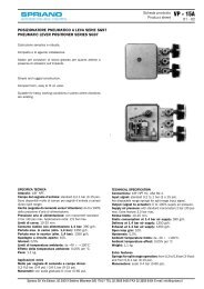
Flush-mount pressure transmitter<br />
CPE 300<br />
New<br />
New<br />
• Ranges from 0/+10 Pa to -1000/+1000 Pa (according to the model)<br />
• Transmitter resolution at 0.1 Pa on CPE 301 (optional)<br />
• Configurable intermediate and centre zero ranges<br />
• Face calibration<br />
• Interchangeable Measuring Sensor (SPI technology)<br />
• Alternating display of 1 to 3 parameters<br />
• External transmitter inputs (<strong>KIMO</strong> Class 200 and 300)<br />
• 4-20 mA (4 wires) or 0-10V output, RS 232, 2 RCR relays 6A/230 Vac<br />
• 2 visual (dual color LED) and audible (buzzer - 80 dB) alarms<br />
• Output diagnostics<br />
• MODBUS network RS 485 system (optional)<br />
• Front made of brushed stainless steel or white lacquered,<br />
with electroluminescent display<br />
Part number<br />
To order, just add the codes to complete the part number :<br />
CPE30<br />
Measuring range<br />
1 -100/+100 Pa<br />
2 -500/+500 Pa<br />
3 -1000/+1000 Pa<br />
-<br />
Front face<br />
B<br />
I<br />
White lacquered stainless steel<br />
brushed stainless steel<br />
Example : CPE302-B = flush-mount transmitter type <strong>CPE300</strong>, with a range of<br />
-500/+500 Pa, and a white lacquered stainless steel housing.<br />
Housing dimensions<br />
For the intermediate and<br />
centre zero ranges, see<br />
“Configuration”.<br />
Transmitter features<br />
Pressure<br />
Measuring range ............................see “SPI features”<br />
Units of measurement....................Pa, mmH O, mbar, inWG<br />
2<br />
Accuracy *......................................± 0,5% of reading ± 1 Pa<br />
± 0,5% of reading ± 0.8 Pa (CPE 301 with 0.1<br />
Pa option)<br />
Zero drift .........................................none (see “self-calibration”)<br />
Resolution ......................................1 Pa - 0,1 mmH2O - 0,01 mbar - 0,01 InWG<br />
Self-calibration...............................push-button or automatic (configurable)<br />
Type of fluid ...................................air and neutral gases<br />
* All accuracies indicated in this technical datasheet were stated in laboratory conditions, and can be guaranted for<br />
measurements carried out in the same conditions, or carried out with calibration compensation.<br />
Housing features<br />
Front face..........................316L wire brushed stainless steel or white lacquered<br />
Back housing....................flushmount, 304L stainless steel<br />
Dimensions ......................see drawing alongside<br />
Display ..............................electroluminescent alphanumeric (38 x 48 mm)<br />
........................................... 4 digits x 8 segments (first line : value of the measurement)<br />
........................................... 4 digits x 12 segments (second line : unit of measurement)<br />
.............................................. protection screen made of PMMA<br />
Display ..............................from 1 to 3 parameters, alternatively (3 seconds)<br />
Height of digits.................14 mm<br />
Back fittings .....................barbed fittings Ø 5,2 mm<br />
Weight ...............................690g
-<br />
SPI system features<br />
Interchangeable Pressure Sensor<br />
The SPI board (Interchangeable Pressure Sensor) includes a<br />
piezoresistive sensitive element with its digital electronic system. This<br />
system is individually adjusted and records all the calibration parameters.<br />
Via the automatic recognition by the transmitter, this digital board is totally<br />
interchangeable. Maintenance, service and calibration are easily<br />
performed on site, with no need to stop the process.<br />
Innovations<br />
Adjustable pressure connections<br />
The CPE 300 has 2 adjustable pressure connections in front (A), coupled with 2<br />
pressure connections at the back (B).<br />
When installing, this system allows you to configure your pressure connections with<br />
a set of plugs (supplied with the transmitter).<br />
A<br />
Black<br />
-<br />
Red<br />
+<br />
Examples of possible mountings<br />
Plugs<br />
Configurable intermediate and centre zero ranges<br />
Probe ref.<br />
SPI 100<br />
SPI 500<br />
SPI 1000<br />
Pressure range<br />
-100/+100 Pa<br />
-500/+500 Pa<br />
-1000/+1000 Pa<br />
The minimum configurable range is 10% of the full scale.<br />
Overpressure tolerated ............25 000 Pa<br />
Response time..........................1/e (63%) 0,3 sec.<br />
Type...........................................digital<br />
Dimensions...............................L = 60 mm, l = 25 mm<br />
Working temperature...............0 to +50 °C<br />
Storage temperature................-10 to +70 °C<br />
B<br />
+ -<br />
+<br />
Open plug<br />
Plug<br />
+<br />
Plug<br />
-<br />
-<br />
Self-calibration<br />
Class 300 transmitters have a temperature compensation system from 0 to 50°C,<br />
and a self-calibration system, to guarantee an excellent long-term stability, along<br />
with a great measurement accuracy.<br />
Self-calibration principle: the microprocessor drives an electro-valve that<br />
compensates for any long-term drift of the sensitive element.<br />
Compensation is made by regular automatic adjustment of the zero.True<br />
differential pressure measurement is then made regardless of the environmental<br />
conditions of the transmitter.<br />
Electro-valve lifetime..............100-million cycles<br />
Benefit.....................................no zero drift<br />
Self-calibration frequency .....can be disabled or set between 1 and 60 min.<br />
Face calibration<br />
This innovative system<br />
allows you to isolate the<br />
back pressure connections,<br />
and then to access the<br />
sensitive element (on the<br />
face) of the transmitter.<br />
Without unmounting the<br />
transmitter, this system<br />
allows you to calibrate by<br />
connecting the transmitter<br />
to a pressure generator and<br />
a calibration bench.<br />
The calibration is easier and<br />
faster.<br />
Plug<br />
+<br />
Red Black<br />
+ -<br />
Calibration<br />
bench<br />
Relays and Alarms<br />
Class 300 transmitters have 4 stand-alone and configurable alarms :<br />
2 visual alarms (dual color LED) and 2 relays (contacts).<br />
You can set :<br />
- 1 or 2 set points (rising and falling action) for each alarm<br />
- the time-delay / 60 sec. max.<br />
- the alarm action (rising or falling)<br />
- the relay operation mode : positive or negative security<br />
-the audible alarm (buzzer) activation.<br />
Integration of pressure measurement<br />
The pressure measurement element is very sensitive and reacts to pressure<br />
changes. When making measurements in unstable air movement conditions, the<br />
pressure measurement may fluctuate. The integration coefficient (from 0 to 9)<br />
makes an average of the measurements ; this helps to avoid any excessive<br />
variations and guarantees a stable measurement.<br />
Technical Specifications<br />
Power supply ...........................24 Vac / Vdc ±10%<br />
Output.......................................1 x 4-20 mA or 1 x 0-10 V (4 wires)<br />
maximum load : 500 Ohms (4-20 mA)<br />
minimum load : 1 K Ohms (0-10 V)<br />
Galvanic isolation....................on the output<br />
Consumption ...........................5 VA<br />
Relays.......................................2 RCR relays 6A / 230 Vac<br />
Visual alarms ...........................2 dual color LED<br />
Audible alarm...........................buzzer<br />
Electro-magnetical compatibility.......EN 61 326<br />
Electrical connection ................screw terminal block for cables Ø 1.5 mm² max<br />
RS 485 communication...........digital : RTU Modbus protocol<br />
.................................................. communication speed configurable<br />
.................................................. from 2400 to 115200 Bauds<br />
RS 232 communication...........digital : ASCII, proprietary protocol<br />
Working temperature (housing) ........0 to +50°C<br />
Storage temperature ..........................-10 to +70°C<br />
Environment........................................air and neutral gases
{<br />
Connection<br />
Front Pressure Connections<br />
+ -<br />
c<br />
Back pressure<br />
connections<br />
e<br />
RS 232 connector<br />
(LCC 300 software)<br />
d<br />
Analogue output<br />
a<br />
Power supply<br />
b<br />
Relay terminal blocks<br />
d<br />
a<br />
a<br />
b<br />
Relay 2 Relay 1<br />
For 24 Vac<br />
power supply models<br />
For 24 Vdc<br />
power supply models<br />
4-20 mA ...........current<br />
GND.................ground<br />
0-10 V ..............voltage<br />
~ ~<br />
- +<br />
NO .............normally open<br />
COM ..........common<br />
NC .............normally closed<br />
NO .............normally open<br />
COM ..........common<br />
NC .............normally closed<br />
Electrical connections - as per NFC15-100 norm<br />
!<br />
This connection must be made by a qualified technician. Whilst making the connection, the transmitter must not be energized.<br />
Power supply connection :<br />
• For 24 Vdc power supply models :<br />
Output signal selection<br />
voltage (0-10 V) or current (4-20 mA)<br />
The on-off switch located on the left side<br />
of the transmitter allows selection of the<br />
required outputs.<br />
Connection of SUB-D15<br />
RS 232 and RS 485 (Modbus)<br />
(see e on connection drawing)<br />
8<br />
7<br />
6<br />
5<br />
4<br />
3<br />
15 14 13 12 11 10<br />
2<br />
9<br />
1<br />
Power supply<br />
terminal block<br />
24 Vdc<br />
power supply<br />
-<br />
-<br />
+<br />
• For 24 Vac power supply models :<br />
230 Vac<br />
Power supply<br />
terminal block<br />
Pe<br />
N<br />
L<br />
power supply<br />
Class II<br />
~<br />
4 5<br />
Vac Vac<br />
~ ~<br />
24 Vac<br />
~<br />
230 Vac<br />
4 5<br />
+<br />
OR<br />
Pe<br />
N<br />
L<br />
N<br />
Ph<br />
power supply<br />
4 5<br />
N L<br />
24 Vac<br />
Down<br />
4-20 mA<br />
Output connection :<br />
• 4-20 mA current output :<br />
4-20 mA GND 0-10 V<br />
Output<br />
terminal block<br />
Regulator display<br />
or PLC/BMS<br />
+<br />
passive type -<br />
• 0-10 V voltage output :<br />
Regulator display<br />
or PLC/BMS<br />
passive type<br />
Up<br />
0-10 V<br />
Output<br />
terminal block<br />
-<br />
+<br />
+<br />
4-20 mA GND 0-10 V<br />
-<br />
-<br />
+<br />
Pin # Description<br />
1 NC *<br />
2 NC *<br />
3 NC *<br />
4 B - (RS485)<br />
5 A + (RS485)<br />
6 NC *<br />
7 NC *<br />
8 NC *<br />
9 RX (RS 232)<br />
10 NC *<br />
11 TX (RS 232)<br />
12 NC *<br />
13 NC *<br />
14 NC *<br />
15 GND (RS 232)<br />
! CAUTION :<br />
NC * --> DO NOT CONNECT
Digital communication<br />
RS 232 communication<br />
• Via the RS 232 connection, CPE 300 can display<br />
alternatively (every 3 sec) 1 or 2 parameters that<br />
are measured by other <strong>KIMO</strong> Class 200 and 300<br />
transmitters.<br />
Benefit : the CPE 300 can display (in addition to the<br />
pressure) other parameters such as temperature and<br />
humidity from a TH 200 (for example).<br />
• Via the RS 232 connection, you can also configure<br />
your transmitter with the LCC-300 software.<br />
• The RS 232 connection cable is available in 2 m, 5 m<br />
or 10 m (maximum) lengths.<br />
Modbus network (RS 485 system)<br />
• Class 300 transmitters can be linked<br />
in one network, on a RS 485 home bus.<br />
They can also be integrated into an<br />
existing network.<br />
Configuration<br />
You can configure all the parameters of the transmitter : units, measuring<br />
ranges, alarms, outputs, channels, calculation formula.... via the different<br />
methods shown below.<br />
Via remote control (optional)<br />
This is convenient to configure the transmitters located in hard to reach<br />
positions. Same method as with a keypad.<br />
Via software (optional) : on all models.<br />
Simple and user-friendly configuration. See LCC-300 user manual.<br />
Via MODBUS (optional) : on all models.<br />
Configuration of all parameters from your PC, via the supervision or data<br />
acquisition software.<br />
Configurable analogue outputs<br />
Configure the range according to your needs : outputs are automatically<br />
adjusted to the new measuring ranges.<br />
Range with centre zero (-50/0/+50 Pa),<br />
with offset zero (-30/0/+70Pa) or<br />
standard range (0 /+100 Pa) => you<br />
can configure your own intermediate<br />
ranges according to your needs,<br />
between 10% and 100% of the full<br />
scale. The minimum configurable range<br />
is 10% of the full scale.<br />
-100<br />
0V<br />
4 mA<br />
RS 485<br />
RS 232<br />
• When a Class 200<br />
RS 232<br />
or 300 transmitter is<br />
connected to a<br />
CP 300 (with RS 232 connection), all the<br />
measurements can be given to the PLC/BMS via the RS 485, with only one<br />
address for the 2 transmitters.<br />
• The RS 485 numerical communication is a 2-wire network, on which the<br />
transmitters are connected in parallel. They are connected to a PLC/BMS via the<br />
RTU Modbus communication system. Since the CP 300 can be configured with<br />
the keypad, the MODBUS enables remote configuration, to measure 1 or 2<br />
parameters, to see the status of the alarms...<br />
Range<br />
0<br />
New range<br />
-100 0 50<br />
0V<br />
4 mA<br />
10V<br />
20 mA<br />
+100<br />
(Pa, mmH2O...)<br />
10V<br />
20 mA<br />
+100<br />
(Pa, mmH2O...)<br />
www.kimo.fr Distributed by :<br />
EXPORT DEPARTMENT<br />
Tel : + 33. 1. 60. 06. 69. 25 - Fax : + 33. 1. 60. 06. 69. 29<br />
e-mail : export@kimo.fr<br />
Calibration<br />
Adjusting and calibration on site :<br />
The professional configuration interface,<br />
with a dynamic pressure calibration<br />
bench, enables you to adjust and<br />
calibrate your transmitters directly on<br />
site or in laboratories.<br />
Certificate :<br />
• Class 300 transmitters are supplied with adjusting certificates.<br />
Calibration certificates are offered as an option.<br />
• The SPI sensitive elements (Interchangeable Pressure Sensor)<br />
are supplied with adjusting certificates.<br />
Mounting<br />
To install the transmitter on a wall, make a cutting of 196 x 70 mm<br />
in the wall. Then drill 4 holes around the cutting as shown below.<br />
Insert the transmitter into the wall and then, swrew the 4 screws<br />
(supplied with the transmitter).<br />
Maintenance<br />
Avoid aggressive solvents.<br />
Protect the transmitter and probes from any cleaning<br />
product containing formol, which may be used for<br />
cleaning rooms or ducts.<br />
Options<br />
RS 485 digital output (Modbus network)<br />
LCC-300 configuration software, with RS 232 cable<br />
Infrared remote control for configuration<br />
Calibration certificate<br />
Transmitter resolution at 0.1 Pa (CPE 301)<br />
Optional accessories<br />
Sliding fittings<br />
Connection fittings<br />
Clear tube<br />
Output diagnostics :<br />
With this function, you can check with a<br />
multimeter (or a regulator/display, or a<br />
PLC/BMS) if the transmitter outputs work<br />
properly. The transmitter output generates<br />
a voltage of 0 V, 5 V and 10 V or a current of<br />
4 V, 12 V and 20 mA.<br />
Pressure connections<br />
Through-connections<br />
Ref. FT ang - CPE 300 - 05/09 D - RCS (24) Périgueux B349 282 095 Non-contractual document - We reserve the right to modify the characteristics of our products without prior notice