to down load Installation specification for the ipso 25 we132 ...
to down load Installation specification for the ipso 25 we132 ...
to down load Installation specification for the ipso 25 we132 ...

You also want an ePaper? Increase the reach of your titles
YUMPU automatically turns print PDFs into web optimized ePapers that Google loves.
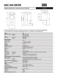
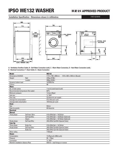
IPSO WE132 WASHER<br />
<strong>Installation</strong> Specification - Dimensions shown in millimetres<br />
APPROVED PRODUCT<br />
I/WE132/09/04<br />
A - Ventilation Overflow Outlet, B - Soft Water Connection (cold), C - Warm Water Connection, D - Hard Water Connection (cold),<br />
E - Electrical Connection, F - Drain Outlet, G - Steam Connection<br />
Model<br />
WE132<br />
Dimensions (HxWxD) 1172 x 780 x 880mm 1310 x 850 x 940mm (Boxed)<br />
Weight Nett 235kg (518lb)<br />
Loaded<br />
288kg (634lb)<br />
Dynamic bot<strong>to</strong>m <strong>load</strong><br />
14700N/7Hz<br />
G-<strong>for</strong>ce 88<br />
Water<br />
No. of inlet valves<br />
1 hot & 2cold (hard & soft)<br />
Recommended temperature (Hot water) 60ºC<br />
Minimum pressure<br />
1.6 bar (<strong>25</strong>psi)<br />
Inlet size<br />
3<br />
/4” BSP<br />
Flow rate<br />
22 litres/min per supply<br />
Average hot consumption<br />
47.5 litres per cycle<br />
Average <strong>to</strong>tal consumption<br />
190 litres per cycle<br />
Drain<br />
Size<br />
50mm<br />
Drain by gravity<br />
80 litres/min<br />
Electrical<br />
Manual<br />
Three phase Self heat 12Kw 415v/50Hz/3ph + N/32A/ph<br />
Self heat 9Kw<br />
415v/50Hz/3ph + N/20A/ph (Optional)<br />
Steam<br />
415v/50Hz/3ph + N/10A/ph (Optional)<br />
Single phase Self heat 9Kw 240v/50Hz/1ph/45A (Special Order)<br />
Coin Op<br />
Three phase Boiler fed 415v/50Hz/3ph + N/10A/ph<br />
Single phase Self heat 9Kw 240v/50Hz/1ph/45A (Special Order)<br />
Boiler fed<br />
240v/50Hz/1ph/16A (Special Order)<br />
Mo<strong>to</strong>r rating<br />
1100watt<br />
Steam<br />
Consumption<br />
13.2Kg/cycle (29lb/cycle)<br />
Pressure<br />
90 - 110psi<br />
Connection<br />
3<br />
/8” BSP<br />
Minimim installation distance Rear<br />
600mm - read fixings on reverse
Foundations<br />
The machine requires a foundation of solid and level concrete construction at<br />
least 400mm deep. If a new concrete pad is <strong>to</strong> be laid it must be keyed<br />
correctly in<strong>to</strong> <strong>the</strong> existing foundations. The concrete foundation should always<br />
be greater in size than <strong>the</strong> machine and a minimum of 100mm from <strong>the</strong> edge of<br />
<strong>the</strong> concrete foundation <strong>to</strong> <strong>the</strong> edge of <strong>the</strong> machine must be provided. It is<br />
recommended that a metal raising plinth is used in conjunction with <strong>the</strong><br />
concrete foundation. This will make <strong>the</strong> installation considerably easier, simplify<br />
<strong>for</strong> future servicing and raise <strong>the</strong> machine above <strong>the</strong> drain level <strong>for</strong> a correct<br />
evacuation of water from <strong>the</strong> machine. A metal raising plinth must be used if<br />
<strong>the</strong> drain level of <strong>the</strong> machine needs <strong>to</strong> be elevated. If block and beam or any<br />
o<strong>the</strong>r type of floor is present, seek advice.<br />
Fixings<br />
A minimum service distance of 600mm is <strong>to</strong> be provided behind <strong>the</strong> machine<br />
(400mm if metal raising plinth is <strong>to</strong> be used). The machine needs <strong>to</strong> be securely<br />
fixed <strong>to</strong> <strong>the</strong> floor by 4 x M16 x 200mm fixing bolts. The type and <strong>specification</strong><br />
of bolts will be determined by <strong>the</strong> quality and type of floor construction. The<br />
following types are generally accepted: rawlbolt, resin bonded fixings (chemfix)<br />
and Thru’ bolts.<br />
Drainage<br />
The machine is fitted with a gravity drain outlet and must be positioned<br />
higher than <strong>the</strong> main drain. The drain outlet must be fitted with a “trap”<br />
removable <strong>for</strong> cleaning purposes. This is <strong>to</strong> ensure against<br />
odour re-circulation. To meet Health and Safety guidelines <strong>the</strong> drain must be<br />
sealed inside <strong>the</strong> building. Where a foul water supply discharges <strong>to</strong> an<br />
outside fouldrain or gully, <strong>the</strong>re is no requirement <strong>to</strong> seal <strong>the</strong> system, as it<br />
must be ventillated and accessible <strong>for</strong> cleaning. The underlying trap will<br />
prevent foul air from rising from <strong>the</strong> sewer. External gullies may be so placed<br />
<strong>for</strong> <strong>the</strong> displacement of surface or rainwater. The only exception <strong>to</strong> this rule is<br />
where <strong>the</strong> foul water discharge from <strong>the</strong> machines is under high pressure,<br />
thus rendering <strong>the</strong> water seal within <strong>the</strong> gully ineffective.<br />
Electrical<br />
Each machine must be individually protected. The isolation point <strong>for</strong> <strong>the</strong><br />
machine should be in a readily accessible position <strong>for</strong> use in an emergency.<br />
All cabling <strong>to</strong> <strong>the</strong> machine shall be sufficiently protected against damage. It<br />
shall be correctly sized <strong>to</strong> <strong>the</strong> current rating of <strong>the</strong> machine. It should be<br />
connected <strong>to</strong> <strong>the</strong> machine using a suitable cable entry fixing. The<br />
commissioning engineer will carry out <strong>the</strong> final connection inside <strong>the</strong><br />
machine. Circuit breakers or fuses can be used <strong>to</strong> protect <strong>the</strong> power supply. If<br />
fuses are used <strong>the</strong>n <strong>the</strong>y must be of <strong>the</strong> mo<strong>to</strong>r rated variety. A responsible<br />
and competent operative should carry out all electrical work and ensure that<br />
all local and national regulations and codes of practice are complied with.<br />
Steam (Optional)<br />
The machine should be connected <strong>to</strong> suitably sized live steam supply<br />
utilising an isolating valve, strainer/trap, electric solenoid inlet valve and a<br />
flexible steam connection hose. (Please note none of <strong>the</strong>se fittings are<br />
supplied with <strong>the</strong> machine). All pipes should be lagged <strong>to</strong> protect against<br />
personal injury. All steam supply pipes should be installed <strong>to</strong> local and<br />
national codes of practice as <strong>the</strong>y <strong>for</strong>m part of a pressurised system.<br />
NOTES:-<br />
Water Supply<br />
The machine is supplied with three water inlet valves, hot, cold hard and cold<br />
soft. If <strong>the</strong>re is no soft water available or it is not needed, <strong>the</strong> soft and hard<br />
connections must come from <strong>the</strong> same supply. (Do not use plastic ‘Y’ pieces).<br />
The machine is fitted with its own Type ‘A’ Air Break System. This means that it<br />
can be connected directly <strong>to</strong> <strong>the</strong> mains supply. Seperate 15mm hot and cold<br />
supplies are required. If more than one machine is <strong>to</strong> be installed, <strong>the</strong>n <strong>the</strong> pipe<br />
sizes should be increased accordingly. These supplies should terminate in<br />
3/4”BSP shut off valves with male threaded ends. If <strong>the</strong> hot water supply is<br />
insufficient in temperature, pressure or flow, <strong>the</strong> machine can <strong>the</strong>n be<br />
connected solely <strong>to</strong> a cold water supply. This can only be done if <strong>the</strong> machine<br />
is equipped with a heating source, i.e. electric elements or a steam supply.<br />
This can however increase cycle times and running costs. A minimum supply<br />
pressure of <strong>25</strong>psi is required <strong>for</strong> each supply. If this is not available cycle times<br />
will increase. To overcome this a booster pump can be fitted: PLEASE SEE<br />
SPECIFICATION FOR FLOW RATE REQUIRED. The hot and cold supplies<br />
should be equal <strong>to</strong> within <strong>25</strong>psi of each o<strong>the</strong>r. In hard water areas its<br />
recommended that <strong>the</strong> water supply is fitted with a water softner. Failure <strong>to</strong> do<br />
so will result in a detrimental effect on some component parts and may effect<br />
<strong>the</strong> standard warranty. NOTE! ALL INSTALLATIONS MUST COMPLY WITH<br />
THE NATIONAL WATER REGULATIONS.<br />
1 WHERE EXISTING SERVICES ARE TO BE CONNECTED TOO,<br />
THE INSTALLER MUST ENSURE THAT THESE ARE<br />
ADEQUATELY SIZED AND THAT THEY ARE IN GOOD WORKING<br />
ORDER. FOR EXAMPLE, IF A WASHER IS TO BE CONNECTED<br />
TO AN EXISTING DRAIN IT MUST BE CHECKED FOR ANY<br />
BLOCKAGES DURING INSTALLATION.<br />
2 FOR MULTIPLE MACHINE INSTALLATIONS SERVICES MUST BE<br />
INCREASED IN SIZE ACCORDINGLY. I.E WATER PIPES,<br />
DRAINAGE PIPES, ELECTRIC CABLES ETC.<br />
All <strong>specification</strong>s subject <strong>to</strong> change without notice