36e Operator's Manual 2011.pdf - Marlow-Hunter, LLC
36e Operator's Manual 2011.pdf - Marlow-Hunter, LLC
36e Operator's Manual 2011.pdf - Marlow-Hunter, LLC

Create successful ePaper yourself
Turn your PDF publications into a flip-book with our unique Google optimized e-Paper software.
<strong>Operator's</strong><br />
<strong>Manual</strong><br />
e36<br />
V 090310
Dear <strong>Hunter</strong> Owner,<br />
<strong>Operator's</strong> <strong>Manual</strong><br />
Thank You!<br />
From the General Manager<br />
Congratulations and welcome to the <strong>Hunter</strong> family! As a <strong>Hunter</strong> owner, you will enjoy the quality and the<br />
attention to detail for which <strong>Hunter</strong> Boats are renowned. <strong>Hunter</strong> and your dealer are committed to your<br />
service and total satisfaction.<br />
This Operator’s <strong>Manual</strong> will acquaint you with the proper operation and maintenance of your new <strong>Hunter</strong><br />
boat, as well as boating safety, which is our primary concern, whether in ports or at sea.<br />
The new boat warranty registration form you signed at the time of delivery will be sent to us by your dealer.<br />
This registers the one year warranty and establishes your contact information in our system. It will also<br />
activate <strong>Hunter</strong>'s Customer Satisfaction program (CSS), our effort to insure the highest level of satisfaction<br />
and enjoyment with your new <strong>Hunter</strong>. Within a few weeks of delivery you will receive a letter asking you to<br />
complete an online questionnaire primarily about your experience with the dealer. Several months later you<br />
will receive a second letter asking you to evaluate the boat. We value your opinion and hope that you will<br />
take the time to complete both surveys.<br />
As you already know, we work with the highest quality equipment manufacturers to supply the components<br />
for your boat. To receive full warranty coverage on all the individual components, such as engine, electronics<br />
and appliances, be sure to complete and return to the Original Equipment Manufacturers (OEM) warranty<br />
cards to activate the individual warranties for these important components. You will find them in the owner's<br />
packet that also contains the OEM manuals for this equipment. Please remember all the information contained<br />
in the OEM manuals supersedes the information contained in this manual.<br />
Finally, if you are new to boating, be certain to learn the proper rules of seamanship to ensure the safety of<br />
your passengers. Refer to Chapman's Piloting, Seamanship, and Small Boat Handling <strong>Manual</strong> for important<br />
and useful information concerning this aspect of boating. Attend a safe boating course offered by the United<br />
States Coast Guard Auxiliary, United States Power Squadron, or any enterprise experienced in conducting<br />
safe boating courses.<br />
Thank you for choosing <strong>Hunter</strong>. I am confident your new boat will provide you and your family with years of<br />
enjoyable boating.<br />
Mike Williams<br />
General Manager<br />
B
<strong>Operator's</strong> <strong>Manual</strong><br />
As the owner of a <strong>Hunter</strong>, you have chosen one of the finest boats money can buy.<br />
<strong>Hunter</strong> Corporation, is one of America’s oldest privately held boating companies. In February 1996 <strong>Hunter</strong> became<br />
an employee ownership company. We continue to be dedicated to giving you a quality boat that will bring you years<br />
of enjoyment whether you’re spending a day at the marina or cruising down a waterway. Performance, dependability,<br />
safety, and comfort is more than just a catchy phrase at <strong>Hunter</strong>. It is the basis for every step of design and construction<br />
to assure you of many pleasure-filled years of boating.<br />
A Proud Heritage<br />
With every <strong>Hunter</strong>, three generations of experience combine with modern engineering and production techniques provide<br />
you one of the most affordable, full featured sailing boats in the industry today.<br />
From the stem to the stern, every piece of equipment and its placement has been engineered to provide the most<br />
seasoned sailer with the best advantage on the water. <strong>Hunter</strong> has included everything to make ours the most complete<br />
sailing vessel on the market today.<br />
How to Use this <strong>Manual</strong><br />
Many people read their operator’s manual from beginning to end when they first receive their new boat. If you do this, it<br />
will help you learn about the features and controls for your new boat. In this manual, you’ll find that pictures and words<br />
work together to explain things quickly.<br />
Table of Contents<br />
A good place to look for what you need is in the Table of Contents in the beginning of this manual. It is a list of the<br />
chapters and the page number where you’ll find them.<br />
Safety Warnings and Symbols<br />
In Boating Safety section you will find a number of cautions, warnings, and danger symbols to tell you about things<br />
that could hurt you.<br />
In this chapter we tell you where the hazards are. Then we tell you what to do to help avoid or reduce them. Please<br />
read this chapter carefully, to prevent yourself or someone else from possible injury.<br />
Any questions regarding your <strong>Hunter</strong> ® or this manual contact Customer Service at:<br />
<strong>Hunter</strong> Corporation<br />
Route 441, Post Office Box 1030<br />
Alachua, FL. USA 32616<br />
Phone: (386) 462-3077<br />
Fax: (386) 462-4077<br />
e-mail: customerservice@huntermarine.com<br />
(8am to 5pm EST) 1-800-771-5556<br />
C
<strong>Operator's</strong> <strong>Manual</strong><br />
Operator’s <strong>Manual</strong> at a Glance<br />
1. Introduction<br />
2. Documents and Forms<br />
3. Warranty<br />
4. Boating Safety<br />
5. Fuel System<br />
6. Underwater Gear<br />
7. DC Electric Systems<br />
8. AC Electric Systems<br />
9. Water Systems<br />
10. Sanitation and Waste Systems<br />
11. Engines and Transmissions<br />
12. Sails and Rigging<br />
13. Getting Underway<br />
14. Maintenance<br />
15. Glossary<br />
D
<strong>Operator's</strong> <strong>Manual</strong><br />
How do I prevent Carbon Monoxide<br />
buildup? ..................... pg.4.6<br />
How do I fuel my boat? . . . . . . . . . pg. 5.4<br />
How do I drain water from my fuel filters?<br />
.............................pg. 5.7<br />
How do I remove my battery? . . . . pg. 7.3<br />
How do I connect shore power?. . pg.8.5<br />
How do I disconnect the shore<br />
power? . . . . . . . . . . . . . . . . . . . . . . pg. 8.5<br />
How do I start my generator power?<br />
. . . . . . . . . . . . . . . . . . . . . . . . . . . . . pg. 8.6<br />
How do I shut down my generator? pg. 8.6<br />
How do I operate my air conditioning? ..<br />
. . . . . . . . . . . . . . . . . . . . . . . . . . . . . pg. 8.6<br />
How do I fill my fresh water tank? pg. 9.2<br />
How do I sanitize my water? ........9.3<br />
How do I connect dockside water? pg. 9.2<br />
How do my bilge pumps work? . pg. 10.3<br />
How do I run my macerator pump? .....<br />
. . . . . . . . . . . . . . . . . . . . . . . . . . . . pg. 10.4<br />
How do I start my engines?. . . . . pg. 13.3<br />
What to do in case of a fire. ....pg. 4.12<br />
Fixing scratches . . . . . . . . . . . . . . pg. 14.3<br />
Periodic maintenance. . . . . . . . . pg. 14.15<br />
Winterization .................pg. 14.8<br />
Lifting and Storing your boat . . . pg. 14.8<br />
E
<strong>Operator's</strong> <strong>Manual</strong><br />
Table of Contents<br />
1. Introduction 1.1<br />
1.1 The <strong>Manual</strong> Packet 1.2<br />
1.2 Your Responsibilities 1.2<br />
1.3 Dealers Responsibilities 1.3<br />
1.4 Sources of Information 1.3<br />
1.5 Equipment Manufacturer <strong>Manual</strong>s 1.4<br />
1.6 Warranties 1.4<br />
1.7 Hull Identification Number 1.4<br />
1.8 Manufacturers Certifications 1.4<br />
1.9 Service Parts and Repair 1.5<br />
2. Forms 2.1<br />
Documents and Forms overview 2.2<br />
Out of Water Inspection 2.4<br />
In Water Inspection 2.7<br />
Pre-Departure Checklist 2.8<br />
After Sailing Checklist 2.9<br />
Pre-Delivery Service record 2.10<br />
Float Plan 2.11<br />
Maintenance Log 2.12<br />
3. Warranty 3.1<br />
Warranty Information 3.3<br />
Restrictions to Warranties 3.5<br />
Owner Information Card 3.6<br />
Warranty registration 3.7<br />
Sample Form Letter 3.8<br />
Graphic Explanation of Warranty 3.9<br />
4. Boating Safety 4.1<br />
4.1 Safety 4.2<br />
4.2 Carbon Monoxide Hazard 4.4<br />
4.3 Other Dangers 4.10<br />
4.4 Fire 4.12<br />
4.5 Distress Signals 4.12<br />
Lightning Illustration 4.15<br />
Interior Arrangement 4.16<br />
General Boat Arrangements 4.17<br />
Dimension & Capacities 4.18<br />
Deck Arrangement 4.19<br />
Deck Hardware List 4.20<br />
F<br />
5. Fuel System 5.1<br />
Fuel Safety Checklist 5.2<br />
5.1 Fuels Tanks 5.3<br />
5.2 Fuel Supply Lines and Hoses 5.4<br />
5.3 Fuel Valves 5.5<br />
5.4 Fuel Filters 5.5<br />
Fuel Filter Reference 5.7<br />
5.5 LPG 5.8<br />
5.6 Troubleshooting 5.10<br />
Fuel System Drawing 5.12<br />
LPG Arrangement 5.13<br />
6. Underwater Gear 6.1<br />
6.1 Mechanical Propulsion Components 6.2<br />
6.2 Steering 6.3<br />
6.3 Seawater Pick-up 6.4<br />
6.4 Windlass and Anchoring 6.4<br />
6.5 Troubleshooting 6.6<br />
Through Hulls Port & Stbd 6.8<br />
Bottom Through Hulls 6.9<br />
7. DC Electric 7.1<br />
7.1 The DC Electrical System 7.2<br />
7.2 Power Supply Equipment &<br />
Components 7.2<br />
7.3 System Componets & Operation 7.5<br />
Troubleshooting 7.10<br />
Basic Power Supply System Diagram 7.11<br />
12 Volt DC Deck Lighting 7.13<br />
8. AC Electric 8.1<br />
8.1 Power Systems & Components 8.2<br />
Troubleshooting 8.8<br />
AC/DC Electric Poer Supply Diagram 8.9<br />
9. Water Systems 9.1<br />
9.1 Water Tanks 9.2<br />
9.2 Pumps 9.3<br />
9.3 Pickups and Strainers 9.4<br />
Troubleshooting 9.6<br />
A/C Plumbing Layout 9.7<br />
Fresh Water Layout 9.9
<strong>Operator's</strong> <strong>Manual</strong><br />
10. Sanitary Systems 10.1<br />
10.1 Drains and Discharges 10.2<br />
10.2 Pumps 10.3<br />
10.3 Other Waste Related 10.4<br />
10.4 Head System 10.5<br />
10.5 Operations and Maintenance 10.5<br />
10.6 Toilets 10.6<br />
Troubleshooting 10.8<br />
Black Water System 10.9<br />
Sump Pump (Grey Water) System 10.11<br />
Bilge Water (Grey Water) Layout 10.13<br />
11. Engines and Transmissions 11.1<br />
11.1 Engines 11.2<br />
11.2 Transmissions 11.4<br />
11.3 Operations and Maintenance 11.4<br />
Troubleshooting 11.6<br />
Engine Exhaust System 11.9<br />
12. Sails and Rigging 12.1<br />
12.1 Main Rig Components 12.2<br />
12.2 The Mast 12.2<br />
12.3 The Boom 12.2<br />
12.4 The Sails 12.3<br />
12.5 Reefing Instructions 12.3<br />
12.6 Reefing Procedure 12.3<br />
12.7 Shaking Out a Reef 12.3<br />
12.8 Spinnaker (Option) 12.3<br />
12.9 The Arch 12.4<br />
12.10 B&R Rig 12.4<br />
12.11 Tuning the B&R Rig 12.4<br />
12.12 Protecting your Rigging 12.6<br />
Sailplans & Sail Specification 12.7<br />
Standing Rigging Detail (Layout) 12.8<br />
Furling Standing Rigging Detail (Layout) 12.9<br />
Upper Spreader Tip Detail 12.10<br />
Lower Spreader Tip Detail 12.11<br />
Standing Rigging Details (Specification)12.12<br />
Conventional Standing Rigging 12.13<br />
Furling Standing Rigging 12.14<br />
Mainsheet Purchase 12.15<br />
Boom to Mainsail Reefing 12.16<br />
Standard Vang Detail 12.17<br />
G<br />
Optional Rigid Vang Detail 12.18<br />
Running Rigging Layouts 12.19<br />
Running Rigging Specification 12.20<br />
Jib Furling Line Layout 12.21<br />
Bridle Configuration 12.22<br />
Lazyjack Installation 12.23<br />
Optional Spinnaker Layout 12.25<br />
13.1 Boarding your Boat 13.2<br />
13.2 Starting the Engine 13.3<br />
13.3 Getting Underway 13.4<br />
13.4 Returning to Port 13.6<br />
13.5 Emergency Operations 13.6<br />
14. Maintenance 14.1<br />
14.1 Maintenance Materials 14.2<br />
14.2 Exterior 14.2<br />
14.3 Interior 14.5<br />
14.4 Mechanical Systems 14.6<br />
14.5 Periodic Maintenance 14.7<br />
14.6 Storage and Lifting 14.8<br />
14.7 Fitting out after Storage 14.10<br />
Routine Maintenance 14.12<br />
Exterior Lifting Points - Stern Drive 14.15<br />
15. Glossary 15.1
Chapter 1<br />
Introduction<br />
e36<br />
V 090310
Introduction<br />
1.1 The <strong>Manual</strong> Packet<br />
This operator’s manual, along with your owner's packet,<br />
has been compiled to help you to operate your boat with<br />
safety and pleasure. The Owner's / <strong>Operator's</strong> <strong>Manual</strong>:<br />
• Describes basic safety information;<br />
• Describes some of the features of your boat;<br />
• Describes the equipment on your boat;<br />
• Contains fundamentals of the use of that equipment;<br />
• Contains fundamentals of the use of your boat.<br />
However, please note that the information in this<br />
manual only summarizes more detailed information<br />
in the equipment manuals. The summaries are<br />
intended to be a convenient reference for daily use.<br />
OEM manuals take precedence over the information<br />
in the manufactures documents.<br />
This information does not give you a course in boating<br />
safety, or how to navigate, anchor, or dock your boat.<br />
Operating a boat, sail or power, requires more skills,<br />
knowledge and awareness than is necessary to operate<br />
a car or truck.<br />
1.2 Your Responsibilities<br />
Please keep this manual in a dry and secure but<br />
readily accessible place and leave it on the boat<br />
at all times! Make sure to hand over this manual<br />
to the new owner if you decide to sell the boat.<br />
If this is your first boat of this type or you are changing<br />
to a new boat you are not familiar with, please<br />
insure that you obtain handling and operating experience<br />
before assuming command. For your safety,<br />
and the safety of your passengers you must:<br />
• Take a course in Boating Safety;<br />
• Get instruction, or aid in the safe and proper handling<br />
of your boat;<br />
• Familiarize yourself and your passengers of the locations,<br />
and use of all safety, and essential operating<br />
equipment.<br />
Understand and follow the rules of the road;<br />
• Learn how to navigate a boat in all sea, and weather<br />
conditions;<br />
• Register your boat, contact state boating authorities,<br />
or the marine dealer for the registration requirements.<br />
Boating Safety courses provide owners and operators<br />
with the opportunity to gain knowledge and experience<br />
in a variety of skills:<br />
• Navigation<br />
• Seamanship and boat handling<br />
• Rules of the Road<br />
• Knowledge of federal, state, and local regulations<br />
• Weather prediction<br />
• Safety at sea<br />
• Survival in bad weather<br />
• Respect for others on the water<br />
• First aid<br />
• Radio communication<br />
• Distress signals<br />
• Rendering assistance to others<br />
• Use of lifesaving equipment<br />
• Pollution control<br />
• Knowledge of the boat and its systems<br />
• Seaworthiness<br />
• Leaving or approaching a dock mooring<br />
• Anchoring and weighing anchor<br />
• Beaching the boat and shallow water operations<br />
• Towing and being towed<br />
• Handling mooring lines and tying up<br />
• Procedures for emergencies including fire, flooding,<br />
collision, and medical emergencies, etc.<br />
Even when your boat is categorized for them, the sea<br />
and wind conditions corresponding to the design categories<br />
A, B, or C (see the design category example at<br />
the end of this section.) can range from strong gale to<br />
severe conditions where only a competent, fit and trained<br />
crew handling a well maintained boat can safely operate.<br />
We would like to hear your comments or suggestions<br />
concerning our manuals. Did you find the information<br />
helpful? Was the information delivered in a clear precise<br />
manner? Was the information thorough enough to help<br />
you with your new boat? Please call us at (904) 827-<br />
2055 to speak to our <strong>Manual</strong> Department, if you have<br />
questions, or comments, concerning the manual. Please<br />
note, this department does not have design or warranty<br />
information you will need to contact those departments<br />
for such information.<br />
1.2
Introduction<br />
Fig. 1.1 Design Categories<br />
Sea and wind conditions for which a boat is<br />
assessed by the International Standard to be<br />
suitable, provided the craft is correctly handled<br />
in the sense of good seamanship and operated<br />
at a speed appropriate to the prevailing sea<br />
state.<br />
Design Category A (“ocean”)<br />
Category of boats considered suitable to operate<br />
in seas with significant wave heights above 4 m<br />
and wind speeds in excess of Beaufort Force 8,<br />
but excluding abnormal conditions, e.g. hurricanes.<br />
Design Category B (“coastal”)<br />
Category of boats considered suitable to operate<br />
in seas with significant wave heights up to 4 m<br />
and winds of Beaufort Force 8 or less<br />
Design Category C (“inshore”)<br />
Category of boats considered suitable to operate<br />
in seas with significant wave heights up to 2 m<br />
and a typical steady wind force of Beaufort Force<br />
6 or less.<br />
Design Category D (“sheltered waters”)<br />
Category of boats considered suitable to operate<br />
in waters with significant wave heights up to and<br />
including 0,30 m with occasional waves of 0,5 m<br />
height, for example from passing vessels, and a<br />
typical steady wind force of Beaufort 4 or less.<br />
REF: EN ISO 12217<br />
An orientation in the general operation and mechanical<br />
systems of your boat;<br />
An explanation of the <strong>Hunter</strong> CSI Program and Hot Alert<br />
process for same.<br />
A copy of the Product Delivery Service Record form”<br />
completed by you and the dealer during your inspection<br />
of the boat;<br />
A review of all warranty information and how to obtain<br />
warranty service;<br />
The complete Owner’s Packet.<br />
If you do not receive these materials, forms, or information,<br />
or you have any questions contact your dealer, or<br />
call 1-800-771-5556<br />
1.4 Sources of Information<br />
In North America, contact one of the following for<br />
Boating courses:<br />
• U.S. Coast Guard Auxiliary<br />
• U.S. Power Squadron<br />
• Canadian Power and Sail Squadrons<br />
• Red Cross<br />
• State Boating Offices<br />
• Yacht Clubs<br />
Contact your dealer or the Boat/U.S. Foundation at 1-<br />
800-336-2628<br />
Outside of North America, contact your boat dealer,<br />
or your government boating agency for assistance.<br />
1.3 Dealer's Responsibilities<br />
In addition to a pre-delivery check and service of your<br />
boat, your dealer should give to you:<br />
A description and demonstration of the safety systems,<br />
features, instruments, and controls of your boat;<br />
<strong>Hunter</strong> supplies you with; and recommends that you read<br />
the following:<br />
Piloting, Seamanship and Small Yacht Handling<br />
(Chapman)<br />
Motor Yacht and Sailing<br />
P.O. Box 2319, FDR Station<br />
New York , NY 10002<br />
1.3
Introduction<br />
<strong>Hunter</strong> recommends that you purchase and read the<br />
following:<br />
Yachtsman Handbook<br />
by Tom Bottomly<br />
Motor Yacht and Sailing<br />
P.O. Box 2319, FDR Station<br />
New York, NY 10002<br />
The Complete Book of Maintenance and Repair<br />
by Dave Kendall<br />
Doubleday and Co.<br />
Garden City, NY 11530<br />
Pleasure Yachting and Seamanship<br />
U.S. Coast Guard Auxiliary<br />
306 Wilson Road Oaklands<br />
Newark, DE 19711<br />
1.5 Equipment Manufacturer <strong>Manual</strong>s<br />
<strong>Hunter</strong> purchased various equipment and components<br />
from other manufacturers and installed them on your<br />
boat while it was being built. Examples include the<br />
engines, pumps, and the generator. Most OEMs (Original<br />
Equipment Manufacturers) have provided operation and<br />
maintenance manuals for your boat’s equipment. Keep<br />
OEM manuals with your <strong>Hunter</strong> <strong>Operator's</strong> <strong>Manual</strong> in a<br />
safe and accessible place. Be sure to pass them along<br />
to the new owner if you sell your boat.<br />
info can be found in the Warranty section, chapter 3 of<br />
the <strong>Operator's</strong> <strong>Manual</strong>.<br />
1.7 Hull Identification Number (HIN)<br />
The "Hull Identification Number" located on the starboard<br />
aft side, is the most important identifying factor, and must<br />
be included in all correspondence and orders. Failure<br />
to include it creates delays. Also of vital importance are<br />
the engine serial numbers and part numbers when writing<br />
about or ordering parts for your engine. Refer to the<br />
engine manufacturers manuals for locations of engine<br />
serial numbers, and record them for future reference.<br />
US-HUNPCXXXDXXX<br />
Hull Number format:<br />
“US” - country origin, “HUN” - Manufacturer, “C” - length<br />
code, “XXX” - hull number, “D” - month code, “X” - year<br />
code, “XX” - model year<br />
1.8 Manufacturers Certifications<br />
As a boat manufacturer <strong>Hunter</strong> builds their products to<br />
guidelines established under the Federal Boat Safety Act<br />
of 1971. The act is promulgated by the U.S. Coast Guard<br />
who has authority to enforce these laws on boat manufacturers<br />
that sell products in the United States. <strong>Hunter</strong><br />
ensures that all of it's products comply with these laws.<br />
NOTE: The OEM manuals take precedence over the<br />
<strong>Hunter</strong> <strong>Operator's</strong> <strong>Manual</strong>. If information in the <strong>Hunter</strong><br />
<strong>Operator's</strong> <strong>Manual</strong> differs from that in the OEM manuals,<br />
follow the information in the OEM manuals.<br />
1.6 Warranties<br />
Nearly all OEM equipment has its own limited warranties.<br />
Warranty registration cards are in your Operator’s<br />
packet.<br />
Locate and read the individual warranties; put them<br />
together for easy, future reference.<br />
For international owner's; your warranty can be found in<br />
your CE compliant Owner's <strong>Manual</strong>.<br />
For U.S. and non-EU compliant countries, your warranty<br />
1.4<br />
The NMMA, National Marine Manufacturers Association,<br />
provides <strong>Hunter</strong> with a third party certification. The<br />
NMMA is an organization that represents the marine<br />
industry and assists manufacturers, boat dealers, marinas,<br />
repair yards and component suppliers in areas of<br />
legislation, environmental concerns, marine business<br />
growth, and state and federal government agency interaction.<br />
The third party certification that <strong>Hunter</strong> participates<br />
in, uses well known Standards and Recommended<br />
Practices of the ABYC, American Boat and Safety Council.<br />
We at <strong>Hunter</strong> participate extensively in the ABYC, which is<br />
all non-profit, and develops and publishes voluntary standards<br />
and recommended practices for boat and equipment<br />
design, construction, service and repair. We utilize all applicable<br />
ABYC standards in the construction of <strong>Hunter</strong> boats.<br />
Finally <strong>Hunter</strong> sells their products worldwide, and as<br />
such must conform to the various rules and regulations<br />
required by other countries. Most notably are the ISO
standards in Europe which require the application of the<br />
CE (Common European) mark. This mark, much like<br />
the NMMA certification here in the U.S., gives you the<br />
boat owner specific information concerning your boat.<br />
Introduction<br />
1.9 Service, Parts, and Repair for your Boat<br />
When your boat needs serviced, parts, or<br />
repair, take it to an authorized <strong>Hunter</strong> dealer.<br />
To find a dealer in your area call 800-771-5556,<br />
or internationally you can call 01-305-824600<br />
To find repair and parts facilities for the equipment installed<br />
on your boat, refer to the manual for that component.<br />
If a problem is not handled to your satisfaction:<br />
Discuss any warranty related problems directly<br />
with the service manager of the dealership or your<br />
sales person. Give the dealer an opportunity to help<br />
the service department resolve the matter for you.<br />
If a problem arises that has not been resolved to your<br />
satisfaction by your dealer, contact <strong>Hunter</strong> at 800-771-<br />
5556, and the appropriate customer service department<br />
information will be provided to you.<br />
1.5
Introduction<br />
Notes:<br />
1.6
Chapter 2<br />
Documents<br />
and<br />
Forms<br />
e36<br />
V 090310
Documents and Forms<br />
Your <strong>Hunter</strong> dealer completes the Pre-Delivery<br />
Inspection Report<br />
(Fig. 2.1) before you take delivery<br />
of your boat. It is the dealer’s responsibility to both you<br />
and to <strong>Hunter</strong> to give your boat a final inspection. The<br />
purpose of this inspection is to assure proper adjustment<br />
and operation of the entire vessel. Your dealer should<br />
provide you with the Pre-Delivery Inspection Report at<br />
the time of delivery.<br />
<strong>Hunter</strong> will not pay warranty costs for items that should<br />
have been covered in the pre-delivery service inspection<br />
and recorded on the Pre-Delivery Inspection Report.<br />
Owners must coordinate with the dealer to insure<br />
<strong>Hunter</strong> warranty registration is completed and returned<br />
to <strong>Hunter</strong>.<br />
Inserted at the end of this section are several records<br />
you will find helpful.<br />
Use the BOAT RECORD (Fig. 2.2) to record all important<br />
information about your boat and its equipment. After<br />
your dealer has recorded all the information, remove the<br />
record from your Owner’s <strong>Manual</strong> and store in a safe<br />
place. Do not keep this form aboard your boat.<br />
The FLOAT PLAN (Fig 2.4) provides a record of your<br />
destination, departure and return times, boat description,<br />
passenger list, and other information about the trip<br />
you have planned. At the bottom of the form is space for<br />
listing emergency phone numbers in case your return<br />
is delayed past the expected time. It also has space for<br />
indicating information about the person filling the report.<br />
Leave the completed form ashore with a responsible<br />
person. We recommend you make several copies of this<br />
form each boating season to make sure you have a good<br />
supply.<br />
The MAINTENANCE LOG (Fig 2.5) helps to keep maintenance<br />
records in one place. Using this log will allow<br />
you to track maintenance work that has been completed<br />
and to determine when maintenance is required. Your<br />
dealer will also find this information helpful. If you decide<br />
to sell your boat, the maintenance record will make your<br />
boat seeable because it tells prospective buyers that you<br />
have taken good care of your boat.<br />
The ACCIDENT REPORT, No one likes to think about<br />
having a boating accident, but boating accidents do<br />
happen. You must file an accident report after a boating<br />
accident just as you must file an accident report after an<br />
automobile accident. A copy of the U.S. Coast Guard<br />
Accident Report is included at the end of this section.<br />
You can get more copies of the report by calling the U.S.<br />
Coast Guard Boating Safety Hotline at 1-800-368-5674.<br />
You must file this report with the U.S. Coast Guard within<br />
48 hours after an accident resulting in one of the<br />
following:<br />
A person disappears from a vessel under circumstances<br />
that indicate death or injury<br />
Personal injury requiring medical treatment beyond first<br />
aid<br />
Damage to the vessel or property damage<br />
Complete loss of the vessel<br />
State statutes determine whether you must file an<br />
accident report in this case. An accident report must be<br />
filed if the damage exceeds a threshold dollar value as<br />
established by the states, the threshold is $100-$200.<br />
Call the Boating Safety Hotline (800-368-5647) to verify<br />
the threshold for a particular state.<br />
Note: State and local agencies may also have accident<br />
reporting requirements. Check with local enforcement<br />
agencies or with your local <strong>Hunter</strong> dealer regarding local<br />
requirements.<br />
All <strong>Hunter</strong> boats are built in compliance with applicable<br />
United States Coast Guard regulations and recommendations<br />
at the time of construction.<br />
<strong>Hunter</strong> boats comply with the standards developed by<br />
the National Marine Manufactures Association (NMMA)<br />
for its Boat Certification Program.<br />
The locator drawings will help you find the location of<br />
devices and equipment.<br />
NOTE: Efforts have been made to make the drawings in<br />
this manual consistent with production. However, in the<br />
effort to improve this vessel, modifications have been<br />
made in the design that may date some of the drawings<br />
in this manual.<br />
On the next few pages you will find sample forms<br />
for some of the issues dealing with your new boat.<br />
Familiarize yourself with these forms, use them, they can<br />
be very handy.<br />
2.2
Documents and Forms<br />
Dear <strong>Hunter</strong> Owner,<br />
Attached you will find a list of items and recommendations that we believe should be incorporated into your own<br />
ongoing list of preventative maintenance items and safety check points. THIS LIST SHOULD NOT BE CONSID-<br />
ERED A COMPLETE SERVICE MANUAL OR THE ONLY ITEMS ON YOUR BOAT IN NEED OF ROUTINE MAINTE-<br />
NANCE, INSPECTION OR ATTENTION.<br />
You will find that we address commonly found optional equipment items installed on <strong>Hunter</strong> boats, as well as most<br />
standard equipment from <strong>Hunter</strong> Marine. Owner’s need to familiarize themselves with individual equipment manuals<br />
on all such items, especially aftermarket purchases or optional equipment installed by your dealer or <strong>Hunter</strong> Marine.<br />
This should insure that you are following the manufacturer’s recommendations for proper maintenance and up-keep.<br />
We strongly recommend that all owners complete a Power Squadron course followed with a complementary boat<br />
inspection before leaving the dock. To locate a Power Squadron in your area please visit < www.usps.org >.<br />
Reviewing and familiarizing yourself with the Chapman’s Piloting <strong>Manual</strong> is also highly recommended<br />
for every boat owner. This manual contains demonstrations for safety drills which should be practiced<br />
routinely, dealing with adverse conditions, general boat handling and recommended safety equipment.<br />
Our opinion is that no boat owner should operate a boat without first reviewing this manual and without<br />
having ready access to it while sailing.<br />
We hope that this list will be beneficial to you in your ongoing maintenance and upkeep. Safe boating!<br />
Thank You<br />
<strong>Hunter</strong> Marine<br />
2.3
Documents and Forms<br />
Preliminary care and maintenance checklist<br />
A qualified Technician should be used if you are not completely confident in your ability to<br />
make repairs or inspections.<br />
Pre-launch inspection<br />
Out of Water Inspection<br />
____ Sacrificial zinc anodes installed<br />
____ Propeller installed with keyway, nuts and cotter pin<br />
____ Propeller shaft turns freely and without excess wobble<br />
____ Struts and shaft log free of corrosion<br />
____ Rudder swings easily & correct with wheel direction<br />
____ Rudder and post inspected for cracks and/or concealed damage (may require removing rudder)<br />
____ Auxiliary tiller handle properly aligned, fits securely and operational<br />
____ All thru-hulls and valves below water line inspected for corrosion, labeled and closed until after launch<br />
____ Bottom paint in satisfactory condition<br />
____ Hull freshly cleaned and waxed (free of gelcoat damage)<br />
____ Mooring, safety lines and fenders onboard and in good condition<br />
____ House & engine start batteries installed and filled with correct electrolyte levels<br />
____ House & engine start battery boxes secured<br />
____ All battery terminals clean and wires secured<br />
____ Engine block & transmission drains closed<br />
____Speed / Depth transducers in place. Speed paddle wheel rotates smoothly<br />
____ Hose clamps on all systems below water line tight<br />
____ Keel bolts tight and clean<br />
____ Exhaust hose attached and secured<br />
____ Boat is free of internal and external water leaks above water line<br />
(Failure to stop water intrusion could result in permanent damage or deterioration of structural coring materials, internal wiring and cause mildew and molding)<br />
Mast Assembly<br />
____ Review manufacturers manual for maintenance and up-keep<br />
____ Spreaders securely fastened<br />
____ Mast and spreaders free of corrosion and stress cracks<br />
____ Standing rigging and pins inspected for wear, tear, corrosion and cracking<br />
____ External wiring secured for anchor, steaming and deck lights<br />
____ Electronic wind indicator installed per manufacturers recommendation<br />
____ <strong>Manual</strong> wind indicator installed on masthead<br />
____ VHF antenna installed and connected<br />
____ Headsail furling system installed inspected per manufacturers recommendation<br />
____ Running rigging inspected for wear and tear<br />
____ Mast step stand-up blocks secured and operational<br />
____ Main Sail, jib sail and flaking system inspected for wear and tear (non-furling mast).<br />
____ In- mast system checked for smooth operation and overall condition of sails<br />
____ Specified pre-bend and diagonal tensions attained in mast. See owners manual<br />
____ Mast to deck wiring properly sealed with drip loop<br />
2.4
Anchor System and Ground Tackle<br />
Documents and Forms<br />
____ Anchor windlass inspected per manufacturers recommendation<br />
____ Anchor secured in bow roller assembly<br />
____ Spare anchor onboard and accessible.<br />
____ See Chapman’s <strong>Manual</strong> for recommendations on anchors, anchor lines and drogues<br />
____ Anchor line pays out and retrieves into anchor locker without difficulty<br />
____ Bitter end of anchor line secured<br />
____ Anchor rode inspected and free of abrasions<br />
____ Anchor chain shackle lock-wired at pin after secured to anchor and corrosion free<br />
____ Anchor locker hatch secures properly with anchor and line in place<br />
____ Anchor locker free of debris inside<br />
____ Anchor locker drains open<br />
Fuel System<br />
____ Tank fuel level indicator functioning properly<br />
____ Fuel clean and treated with engine manufacturers recommended additives<br />
____ Primary and secondary filters cleaned or replaced<br />
____ Fuel tank supply valves open<br />
____ Fuel tank vent clear from tank to atmosphere (hose has anti-siphoned loop in place at hull or deck side)<br />
Steering System<br />
____ Inspect and service steering system according to manufacturer’s recommendation<br />
____ Clean and grease autopilot drive chains<br />
____ Ensure compass light is operational<br />
Primary Pumps Functional<br />
____ <strong>Manual</strong> bilge pumps<br />
____ Electric bilge pumps and float switches (discharge hose has anti-siphon loop in place to prevent back flow under sail)<br />
____ Macerator pumps<br />
____ Fresh water pumps<br />
____Toilet flush pumps<br />
____ Shower sump pumps<br />
____ High water bilge alarm pump<br />
Illumination and small electrical components check<br />
____ Bow light<br />
____ Cabin lights<br />
____ Stern light<br />
____ Deck light<br />
____ Instrument lamps<br />
____ Masthead light<br />
____ Chart light<br />
____ Anchor light<br />
____ Courtesy lights<br />
____ Reading lights<br />
____ Distribution panel lights<br />
2.5
Documents and Forms<br />
____ Smoke detectors operational<br />
____ CO detectors operational (one per cabin recommended)<br />
____ Engine & generator room blower operational<br />
____ Auto fire suppression system operational (engine compartment)<br />
____ Shore power cord and adapter plug operational. See manufacturer’s manual for complete details<br />
____ 110 or 220 VAC outlets operational - Ground fault circuits functioning<br />
____ 110 or 220 VAC inverter/battery charging systems functioning properly<br />
____ Cockpit control systems operational<br />
Fresh Water Systems<br />
____ Hot water heater drains shut<br />
____ All spigots and hose bibs shut<br />
____ All tanks flushed clean and free of debris and antifreeze<br />
____ Water heater tank and lines flushed of antifreeze<br />
____ All water lines and components purged of air and checked for leaks<br />
____ Sinks and drains checked for leaks and adequate flow<br />
____ Cockpit shower operational<br />
____ Fresh water filters clean<br />
____ Tank water level indicator systems operating- labeling and tank valve selection correspond<br />
Head and Holding Tank Systems<br />
____ Vent clear from tank to atmosphere<br />
____ Filled with fresh water and test pumped with macerator<br />
____ Toilets flush to holding tanks properly<br />
____ Waste level indicating system properly functioning<br />
____ No leaks at any hose fitting within the system<br />
Galley Systems<br />
____ Gas bottle filled installed and connected to regulator. Inspect Gas system for leaks after 3 minutes.<br />
Should a leak be detected immediately close the main valve exit boat and seek professional assistance for a<br />
thorough inspection.<br />
____ Stove and oven operational. Refer to manufacturer’s manual for proper operation and trouble shooting.<br />
____ Gimbal latch secure and operational<br />
____ LPG stowage locker drain open and tank storage area free of derbies.<br />
____ Microwave operational<br />
____ Refrigerator operational and proper temperature attained<br />
____ Freezer operational and proper temperature attained<br />
____ USCG waste disposal-warning poster onboard or in owner’s package<br />
____ Icebox drains to sump or bilge properly<br />
____ Icebox drain plugs installed<br />
Topside Inspection<br />
____ Swim seats / ladders / gates operational<br />
____ Swim seat latch operating correctly<br />
____ Cockpit hatches operate properly (adjustments should be made with boat in water)<br />
____ Canvas properly cleaned and installed<br />
____ Cockpit cushions cleaned and installed<br />
____ Lifeline fittings tight and secure<br />
2.6
Documents and Forms<br />
____ Rubrail sealed secured to hull<br />
____ Sliding hatches drains free of debris<br />
____ Companionway drop-ins fit properly in companionway and stowage rack<br />
____ Load bearing hardware securely fastened. This includes but is not limited to chainplates, winches and handrails<br />
____ Traveler arch securely fastened. Stainless Steel models should be properly grounded<br />
See owners manual for details<br />
____ Plexiglas hatches, ports, windscreens and windows adjusted and cleaned.<br />
Cleaners and polishers specifically for Plexiglas can be purchased from most marine supply stores<br />
____ External teak cleaned and oiled (Teak decking cleaned with mild soap and water)<br />
____ External railings cleaned with soap and water then hand polished using automotive wax<br />
____ All deck fill caps seal properly and have retainer chains intact (except Waste Pump-out)<br />
____ Dorade vents or sealing caps installed<br />
____ Topside surface clean and free of gelcoat damage<br />
Interior Inspection<br />
____ Drop-in hatches for bunks and floors in place and fit securely<br />
____ Interior steps and grab rails secured<br />
____ Bilges clean and free of debris<br />
____ Opening port and hatch screens in place<br />
____ Blinds / privacy curtains, shades and interior cushions cleaned, installed and secured<br />
____ All doors open / shut / latch properly<br />
____ Insure all wires and connection on distribution panels are tight (should be<br />
professionally inspected)<br />
____ Television / VCR operational<br />
____ Stereo / Tape / CD operational<br />
____ Chapman’s <strong>Manual</strong> onboard and readily available<br />
____ Safety gear onboard readily available and up to date.<br />
See Chapman’s <strong>Manual</strong> and US Coast Guard website at < www.uscg.mil >for details.<br />
____ Boat owner’s manual onboard<br />
In Water Inspection<br />
Dockside inspection of Engine, Pre-start sequence and operating system<br />
____ Review engine manual for maintenance requirements and proper starting procedure<br />
____ Propeller shaft properly aligned (per engine manual)<br />
____ Shaft to engine coupling bolted and properly torque (per engine manual)<br />
____ All engine mounting bolts in place and properly torque (per engine manual)<br />
____ Crankcase oil at full mark (per engine manual)<br />
____ Transmission fluid / oil at full mark (per engine manual)<br />
____ Coolant mix ratio proper - heat exchanger and expansion tanks full (per engine manual)<br />
____ Seawater intake valve open and no leaks<br />
____ Air bled from fuel lines and system<br />
____ No fuel leaks at any fittings<br />
____ Throttle linkages smooth and operational<br />
____ Shutdown system operational<br />
____ USCG Oil Discharge warning poster in place<br />
____ Exhaust elbows and hoses tight<br />
____ Starting sequence and alarms correct<br />
____ Oil pressure acceptable (per engine manual)<br />
____ Coolant temperature acceptable (per engine manual)<br />
2.7
Documents and Forms<br />
____ Alternator DC output at rated rpm (per engine manual)<br />
____ Correct Idle rpm (per engine manual)<br />
____ Water discharged with exhaust<br />
____ Hour meter operational<br />
____ Fuel level indicators operational<br />
____ Throttle cable tension set properly<br />
____ Shifter operation correct<br />
____ Neutral safety start switch operational<br />
____ No inboard exhaust gas leaks<br />
____ No fuel / oil / water leaks on engine<br />
____ Shaft packing / Drip free Seal adjusted and locknuts tight.<br />
One to three drips per minute with shaft turning on traditional packing assembly<br />
____ Engine box installed and secured<br />
Dockside inspection of Generator, Pre-start sequence and operating system<br />
____ Review and follow manufacturer’s manual for maintenance and up-keep<br />
____ Seawater strainer water-tight and clean<br />
____ No leaks in fuel system - Fuel filters clean<br />
____ Lube oil at full mark<br />
____ Coolant level full - proper mix ratio with water (per generator manual)<br />
____ Seawater discharge overboard with exhaust gas<br />
____ No inboard water or exhaust gas leaks<br />
____ Proper voltage output to distribution panel (per generator manual)<br />
____ Ship / Shore power transfer panel function properly<br />
____ Starter battery box secured<br />
____ Starter battery cable connections clean and tight<br />
____ Starting battery electrolyte level proper<br />
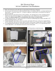
Climate Control System<br />
____ Review and follow manufacturers manual for maintenance and up-keep<br />
____ Seawater strainer water tight and clean<br />
____ Seawater pump air purged and operational<br />
____ Seawater flow adequate fwd and aft<br />
____ Fwd system functions properly in all modes of operation<br />
____ Aft system functions properly in all modes of operation<br />
____ No seawater leaks in system components and lines<br />
____ No condensation leaks to deck or liner<br />
____ Air return/intake filters clean and clear<br />
____ 110 or 220 VAC shore power wired correctly at dock<br />
____ Remote control units and display features operate correctly<br />
____ Condensation drains open<br />
____ Check bilge for extra water<br />
____ Check weather conditions and tides<br />
____ Check food Supply<br />
____ Foul weather gear<br />
____ Linen, sleeping bags<br />
____ Fuel<br />
Pre-departure Checklist<br />
2.8
Documents and Forms<br />
____ Water<br />
____ Sunscreen and sunglasses<br />
____ Tools<br />
____ Docking and anchoring gear<br />
____ Check radio operation<br />
____ Navigation charts and instruments<br />
____ Float plan to a friend or Coast Guard<br />
____ Fuel for Stove<br />
____ Cooking and eating utensils<br />
____ check battery water level<br />
____ oil level, tight V-belts<br />
____ Check for loose electrical connections in the engine compartment<br />
____ Secure loose tools or equipment in the engine compartment so as to not get fouled in the engine.<br />
____ AC systems off, electrical cord stowed<br />
____ Doors and drawers secure<br />
____ Check steering lock to lock<br />
____ Check mast for rigging irregularities and tightness<br />
____ Halyards and sheets are ready to run<br />
____ no lines or obstructions near propeller or bow<br />
____ Anchor ready to run<br />
____ Check lifelines for tightness<br />
____ Turn on waterlines<br />
____ Stow all loose gear<br />
____ Open engine cooling water thru intake valve<br />
After Sailing Checklist<br />
When leaving your <strong>Hunter</strong> at the dock for more than a short time, it is a good idea to review the following checklist to make sure<br />
everything is in order. This will help protect the various parts of your boat and add considerably to their attractiveness and usable<br />
life.<br />
____ Flake or furl mainsail and cover, or remove and bag.<br />
____ Remove and stow all portable deck hardware such as snatch blocks, winch handles, etc.<br />
____ Secure the boom to the topping lifts and set it firmly amidships with the main sheet purchase.<br />
(It is also a good idea to rig a line from the steering wheel or tiller to a convenience cleat to keep the rudder from swinging<br />
back and forth with the motion of the water or employ the wheel brake if so equipped.)<br />
____ Attach the shackle ends of all halyards to convenient fittings and take up slack. Find a location leading away from the mast<br />
to keep the halyard from slapping the mast.<br />
____ Coil and stow all lines in line lockers<br />
____ Cover the winches and steering pedestal when leaving the boat for several days or more<br />
____ Close all fuel lines and seacocks<br />
____ Switch off the electrical system<br />
____ Pump out the bilge<br />
____ Check air vents, secure ports and hatches, swab the deck, and clean deck stainless, particularly if you have operated in salt<br />
water.<br />
2.9
Fig. 2.1<br />
Documents and Forms<br />
DEALER: _____________________________ ENGINE:_________________________________<br />
MAKE:_______________________________ OWNER: ________________________________<br />
PORT ENGINE NO: ____________________ STBD. ENGINE NO: _______________________<br />
BOAT<br />
NAME:__________________________REGISTRYR<br />
NO:_________________________ ___<br />
OPERATION___________INITIALS________<br />
OPERATION____________<br />
INITIALS_________<br />
BEFORE LAUNCHING<br />
BEFORE STARTINGT<br />
ENGINES<br />
1. Hull Side Clean and Gelcoat<br />
23. All engine wiring in good order & tight<br />
2. Bright work clean and finish<br />
24. Throttle control and cable travel<br />
3. Decks cleaned and gelcoat<br />
25. Clutch control and cable travel<br />
4. Interior Finish<br />
26. Crankcase oil level at FULL mark<br />
5. Upholstery clean and carpet in place<br />
27. Reverse gear oil level at FULL mark<br />
6. Bilge cleaned.<br />
7. Bottom clean and paint<br />
28. No fuel leaks in fuel lines, at fittings, at<br />
8. Both shafts turn freely<br />
fuel filter, fuel pump<br />
9. Engines and Generator intakes installed<br />
29. No engine water or oil leaks<br />
10. All hull fittings sealed<br />
11. All drain plugs tight, (hull, engines, generator, muffler) 30. Oil pressure and exhaust water flow<br />
12. Sacrificial Anodes installed10<br />
31. Idling speed set at 700-800 RPM<br />
and is in proper adjustment<br />
WITH BOAT<br />
IN WA<br />
TER<br />
13. Hose test for cabin and window leaks<br />
14. No water leaks at thru hull fitting<br />
with seacocks<br />
15. No water leaks at shaft or rudder<br />
16. With all switches off<br />
- no spark when<br />
battery cable touched to post<br />
17. All electrical equipment operating<br />
including: horn( ); running light( );<br />
bilge pump( )<br />
18. Toilet<br />
operates<br />
19. Water (pressure) system operates<br />
20. Galley stove operates<br />
21. With fuel tanks full, no fuel leaks at<br />
fill pipes, overflow vent, or at<br />
any fuel line connections<br />
22. With coupling disconnected, engine and<br />
shaft alignment<br />
INSPECTION DATE:____________________<br />
___<br />
DEALERS SIGNATURE: _______________________________________________________<br />
OWNERS SIGNATURE:<br />
Pre-delivery Service Record<br />
WA<br />
TER TEST BOAT<br />
33. Engine performance<br />
34. Instruments are registering properly<br />
35. Top RPM wide open throttle for one<br />
minute after warm-up<br />
36. Boat performance<br />
FINAL CHECK:<br />
37. All accessory equipment operating<br />
38. Carpets and drapes installed and clean<br />
39. All loose equipment on boat<br />
ready for new owner.<br />
___________________________________________________________<br />
COMMENTS:____________________________ __________________________________________<br />
_______________________________________________________________________________<br />
2.10
Documents and Forms<br />
Float Plan<br />
Name of Operator____________________________________________________Age____________________<br />
Address____________________________________________________________________________________<br />
Phone______________________________________________________________________________________<br />
Boat Make ________________________________ Model__________________________________<br />
Length _______________________ Hull Color_________________Deck Color___________________________<br />
Registration No._____________________________Home Port________________________________________<br />
Radio frequencies____________________________________________________________________________<br />
Equipment on Board, PFDs, Flares, Anchor<br />
______________________________________________________<br />
___________________________________________________________________________________________<br />
Fuel Capacity ______________________________ Water Capacity____________________________________<br />
Distinguishing Features________________________________________________________________________<br />
____________________________________________________________________________________________<br />
Departed from_______________________________________________________________________________<br />
Date____________________________________________ Time________________________________________<br />
Destination__________________________________________________________________________________<br />
Stops_______________________________________________________________________________________<br />
Estimated time of Arrival: Date_______________________Time________________________________________<br />
Name, age, address and phone number of other persons on board:<br />
_______________________________________________________________________________________<br />
_______________________________________________________________________________________<br />
_______________________________________________________________________________________<br />
_______________________________________________________________________________________<br />
_______________________________________________________________________________________<br />
_______________________________________________________________________________________<br />
2.11
Documents and Forms<br />
Maintenance Log<br />
Date Maintenance Performed Hourmeter<br />
2.12
Documents and Forms<br />
Maintenance Log<br />
Date Maintenance Performed Hourmeter<br />
2.13
Documents and Forms<br />
(Several copies may be required to complete each of the following categories)<br />
Chapman’s Piloting recommended operating techniques, maintenance inspections<br />
and safety points for my particular boat length and type of sailing<br />
2.14
Documents and Forms<br />
Recommendations made by manufacturers of original equipment for proper maintenance<br />
and up-keep<br />
2.15
Documents and Forms<br />
Power Squadron recommendations for maintenance and safe boating<br />
2.16
Documents and Forms<br />
Local sailing club or marina’s recommendations for maintenance and up-keep<br />
2.17
Documents and Forms<br />
List of onboard safety equipment and location<br />
(A copy should be posted onboard at all times)<br />
2.18
Documents and Forms<br />
Spare Parts List<br />
2.19
Documents and Forms<br />
Dates of practice drills and onboard safety inspections<br />
2.20
Documents and Forms<br />
My personal preferences for maintenance items & safety gear<br />
2.21
Documents and Forms<br />
Notes:<br />
2.22
Chapter 3<br />
Limited<br />
Warranty<br />
DC 071609
<strong>Hunter</strong> • Limited Warranty<br />
This Page Intentionally Left Blank<br />
3.2
<strong>Hunter</strong> • Limited Warranty<br />
Your <strong>Hunter</strong> Limited Warranty<br />
<strong>Hunter</strong> offers a limited warranty on every <strong>Hunter</strong> boat sold through an authorized <strong>Hunter</strong><br />
dealer. A copy of this warranty is included here, and in your <strong>Operator's</strong> <strong>Manual</strong>. If for some reason<br />
you are not able to understand, read, or view this manual, please contact your local dealer<br />
for a replacement copy.<br />
We stand behind the quality of your boat with our limited warranty, which you should review.<br />
To insure the operation and validity of your limited warranty, please complete the attached card<br />
and send it to us within ten (10) days of the purchase date. Section 15 of the U.S. Federal<br />
Boat Safety Act requires registration of a boat’s first owner. The warranty data should also be<br />
re-corded in the space below for your own reference.<br />
The following warranties apply to all 2011 Model Year boats produced by<br />
HUNTER MARINE CORPORATION:<br />
LIMITED ONE-YEAR WARRANTY<br />
<strong>Hunter</strong> Marine warrants to the first-use purchaser and any subsequent owner during the limited<br />
warranty period that any part manufactured by <strong>Hunter</strong> will be free of defects caused by faulty workmanship<br />
or materials for a period of twelve (12) months from the date of delivery to the first-use purchaser<br />
under normal use and service. During this period, as the sole and exclusive remedy, <strong>Hunter</strong>’s<br />
obligation under the warranty is limited to the repair or replacement of any such defective part.<br />
LIMITED FIVE-YEAR HULL STRUCTURE AND BOTTOM BLISTER WARRANTY<br />
<strong>Hunter</strong> warrants to the first-use purchaser and any subsequent owner during the limited warranty<br />
period that the hull of each boat will be free from structural defects in materials and workmanship<br />
for a period of five (5) years from the date of delivery to the first-use purchaser under normal use<br />
and service.<br />
This limited warranty applies only to the structural integrity of the hull and the supporting pan/grid<br />
or stringer system. Hulls, pan/grid or stringers modified in any way or powered with engines other<br />
than the type and size installed or specified by <strong>Hunter</strong> are not covered by this limited warranty.<br />
As the sole and exclusive remedy, <strong>Hunter</strong>’s obligation under the warranty is limited to repair or<br />
replacement of any such defective part.<br />
3.3
<strong>Hunter</strong> • Limited Warranty<br />
<strong>Hunter</strong> also warrants to the first-use purchaser and any subsequent owner during the warranty<br />
period that the boat will be free from gelcoat blistering on underwater surfaces of the hull, excluding<br />
the keel and rudder, for a period of five (5) years from the date of delivery to the first-use<br />
purchaser under normal use and service. During this period, <strong>Hunter</strong> will supply or reimburse an<br />
authorized <strong>Hunter</strong> dealer for all of the parts and labor required to repair a blistered underwater<br />
surface of the hull. The labor cost reimbursement will be based on the Labor Allowance Schedule<br />
established by <strong>Hunter</strong> from time to time, however if the repair is performed by a non-<strong>Hunter</strong><br />
dealer, the repair cost must be authorized by <strong>Hunter</strong> in advance and be based on a reasonable<br />
number of hours as determined by <strong>Hunter</strong>. <strong>Hunter</strong> will not pay transportation, hauling, launching,<br />
bottom paint, storage, dockage, cradling rental, rigging and derigging, or other similar costs. It is<br />
recommended that the repair be done during a seasonal haul out for service or storage.<br />
PLEASE KEEP THIS MANUAL IN A SAFE PLACE AND HAND IT OVER TO THE<br />
NEW OWNER IF YOU SELL THE CRAFT.<br />
You should also complete the warranty cards for your engine, stove, head, electric water pump<br />
and other accessories. These are enclosed in the manufacturers’ manuals that are packaged<br />
with your owner’s manual.<br />
HUNTER EXPRESSLY DISCLAIMS THE IMPLIED WARRANTIES OF<br />
MERCHANTA BILITY AND FITNESS. NEITHER HUNTER OR THE SELLING DEALER SHALL<br />
HAVE ANY RESPONSIBILITY FOR LOSS OF USE OF A BOAT, LOSS OF TIME,<br />
INCONVENIENCE, COMMERCIAL LOSS, OR CONSEQUENTIAL DAMAGES.<br />
3.4
<strong>Hunter</strong> • Limited Warranty<br />
The following circumstances will void the bottom blister limited warranty:<br />
(1) If the gel-coat has been sanded, sandblasted, or subjected to abrasion or impact.<br />
(2) If the instructions provided in the <strong>Hunter</strong> Owner’s <strong>Manual</strong> are not followed according to<br />
<strong>Hunter</strong>’s required bottom preparation procedures.<br />
These limited warranties do not cover:<br />
RESTRICTIONS APPLICABLE TO WARRANTIES<br />
(1.) Paint, sealants, adhesives, window glass, Gelcoat, upholstery damage, plastic finishes,<br />
engines, engine parts, bilge pumps, stoves, blowers, pressure water pumps, propellers, shafts,<br />
rudders, controls, instruments, keels and equipment not manufactured by HUNTER. Any warranty<br />
made and issued by the manufacturer of such items will be, if and where available, provided<br />
to the first use purchaser.<br />
(2.) Problems caused by improper maintenance, storage, cradling, blocking, normal wear and<br />
tear, misuse, neglect, accident, corrosion, electrolysis or improper operation.<br />
(3) Boats used for commercial activities including charter.<br />
THESE LIMITED WARRANTIES ARE YOUR SOLE AND EXCLUSIVE REMEDIES AND ARE EXPRESSLY IN<br />
LIEU OF ANY AND ALL OTHER REMEDIES AND WARRANTIES EXPRESSED AND IMPLIED, INCLUDING THE<br />
WARRANTIES OF MERCHANTABILITY AND FITNESS FOR A PARTICULAR PURPOSE, WHETHER ARISING<br />
BY LAW, CUSTOM, CONDUCT, OR USAGE OF TRADE. SOME STATES DO NOT ALLOW LIMITATIONS ON<br />
HOW LONG AN IMPLIED WARRANTY LASTS, SO THE ABOVE LIMITATION MAY NOT APPLY TO YOU. IN THE<br />
EVENT THAT IMPLIED WARRANTIES ARE FOUND TO EXIST UNDER THE LAW OF A PARTICULAR STATE,<br />
NOTWITHSTANDING THE EXCLUSION CONTAINED HEREIN, THE DURATION OF ANY SUCH IMPLIED<br />
WARRANTY SHALL BE LIMITED TO THE DURATION OF THE APPLICABLE LIMITED WARRANTY STATED<br />
HEREIN. THE PURCHASER ACKNOWLEDGES THAT NO OTHER REPRESENTATIONS WERE MADE TO<br />
HIM OR HER WITH RESPECT TO THE QUALITY OR FUNCTION OF THE BOAT. ANY ORAL STATEMENT OR<br />
PRINTED MATERIAL ADVERTISING THE BOAT WHICH SPEAKS TO ANY PERFORMANCE CHARACTERISTIC<br />
OF THE BOAT OR ANY OF ITS COMPONENTS SHALL BE CONSIDERED AND CONSTRUED AS AN ESTIMATED<br />
DESCRIPTION ONLY AND SHOULD NOT BE RELIED UPON AS AN EXPRESS WARRANTY OR AS THE BASIS<br />
OF THE BARGAIN FOR THE BOAT OR ANY OF ITS COMPONENTS.<br />
ANY CONSEQUENTIAL, INDIRECT OR INCIDENTAL DAMAGES WHICH MAY BE INCURRED ARE EXCLUDED<br />
AND PURCHASER’S REMEDY IS LIMITED TO REPAIRS OR REPLACEMENT OF ANY SUCH PART(S).<br />
SOME STATES DO NOT ALLOW THE EXCLUSION OR LIMITATION OF INCIDENTAL OR CONSEQUENTIAL<br />
OR INDIRECT DAMAGES, SO THE ABOVE LIMITATION OR EXCLUSION MAY NOT APPLY TO YOU. THIS<br />
WARRANTY GIVES YOU SPECIFIC LEGAL RIGHTS, AND YOU MAY ALSO HAVE OTHER RIGHTS WHICH VARY<br />
FROM STATE TO STATE.<br />
3.5
<strong>Hunter</strong> • Limited Warranty<br />
OWNER INFORMATION CARD<br />
HULL IDENTIFICATION NUMBER IS ON THE STARBOARD AFT SIDE OF THE HULL OR<br />
TRANSOM. THIS NUMBER MUST BE GIVEN IN ALL NECESSARY CORRESPONDENCE.<br />
HULL NO.<br />
DATE DELIVERED TO OWNER<br />
YACHT NAME<br />
OWNER NAME<br />
STREET ADDRESS<br />
CITY STATE/COUNTRY ZIP CODE<br />
HOME PORT<br />
ENGINE MODEL SERIAL NO. PROPELLER SIZE<br />
DEALER<br />
PHONE<br />
STREET ADDRESS<br />
CITY STATE/COUNTRY ZIP CODE<br />
CUSTOMER SERVICE / WARRANTY<br />
3.6
<strong>Hunter</strong> • Limited Warranty<br />
WARRANTY REGISTRATION<br />
These limited warranties shall not be effective unless the HUNTER Warranty Registration Form<br />
and Pre-Delivery Service Record, which are furnished with each new boat, are filled out completely<br />
and re-turned to HUNTER within ten (10) days of delivery.<br />
Return of the Warranty Registration Form to HUNTER, signed by both Dealer and Owner, is critical.<br />
Warranty coverage cannot be initiated until the completed form is received at HUNTER.<br />
All repairs and/or replacements will be made by an authorized <strong>Hunter</strong> dealer, or at the option of<br />
<strong>Hunter</strong>, at the <strong>Hunter</strong> plant. If the repairs are of such a nature that the warranty work must be<br />
performed at the HUNTER plant, transportation costs to and from the HUNTER plant shall be<br />
paid by the owner. The labor cost reimbursement will be based on a Labor Allowance Schedule<br />
established by HUNTER and where not applicable, on a reasonable number of hours as determined<br />
by HUNTER. Any repairs and replacements must be approved in advance by an authorized<br />
HUNTER service representative.<br />
TRANSFER OF LIMITED WARRANTIES<br />
For 1995 and later hull numbers, the limited warranties will be transferred to a subsequent purchaser<br />
of the boat if:<br />
(1) A notice of the transfer of ownership of the boat is given by the subsequent purchaser in<br />
writing to <strong>Hunter</strong> within thirty (30) days of the transfer.<br />
(2) The notice shall include the name, address and telephone number of the subsequent purchaser,<br />
the date of purchase, the hull number and the name of the seller of the boat.<br />
<strong>Hunter</strong> will mail to the subsequent purchaser notice of the expiration dates of the limited warranties<br />
(see form letter, attached). The transfer of the ownership of the boat will not extend the<br />
expiration dates of the limited warranties.<br />
3.7
<strong>Hunter</strong> • Limited Warranty<br />
SAMPLE FORM LETTER<br />
March 12, 1997<br />
Mr. John Smith<br />
1456 Joy Street<br />
Sarasota, FL 34266<br />
Dear Mr. Smith,<br />
Thank you for providing written notice of transfer of ownership. We are pleased you have<br />
selected a <strong>Hunter</strong> sailboat and we will make every effort to assure <strong>Hunter</strong> ownership will be a<br />
satisfying experience for you.<br />
Based on the information you have provided, we are pleased to notify you of the expiration dates<br />
of the limited warranties.<br />
• The limited one-year New Boat warranty expires (d)_____________________.<br />
• The limited five-year Hull Structure and Bottom Blister warranty expires (d)__________.<br />
Should you require assistance at any time during ownership, we encourage you to contact your<br />
<strong>Hunter</strong> dealer or to call us directly at 386-462-3077.<br />
SAMPLE<br />
E<br />
Please confirm the information at the bottom of the page and advise us if any corrections<br />
are required.<br />
_____________________________________<br />
Customer Service Manager<br />
--------------------------------------------------------------------------------------------------------------------------------<br />
Hull No: HUN__________________________Model:__________________________________<br />
Telephone: (H)________________________(B)______________________________________<br />
Date of Purchase:______________________________________________________________<br />
Purchased From: Name:_______________________________________________________<br />
Address:_________________________________________________________<br />
City/State_________________________________Zip_____________________<br />
( ) Private Owner ( ) Dealer<br />
3.8
Internal fiberglass pan<br />
and fiberglass grid<br />
system are covered by<br />
the five-year limited<br />
warranty.<br />
<strong>Hunter</strong> • Limited Warranty<br />
GRAPHIC EXPLANATION OF WARRANTY COVERAGE<br />
All fiberglass tabbing, overlays ,<br />
adhesives, epoxy and secondary<br />
bonding are covered only by the<br />
one-year limited warranty. They<br />
are not covered by the five-year<br />
limited warranty.<br />
Footnote 1. All wooden bulkheads, modular components, floors, floor<br />
supports , paneling, trim, coring materials, faceplates, countertops,<br />
fiberglass tabbing, overlays, secondary bonding , sealants , adhesives,<br />
gaskets and epoxies are covered only by the one-year limited warranty.<br />
They are not covered by the five-year limited warranty.<br />
Footnote 2. Voids located within the deck or hulls gelcoat<br />
surface or build laminate are covered only by the one-year<br />
limited warranty. They are not covered by the five-year limited<br />
warranty.<br />
Footnote 3. Keel and rudder are not covered under<br />
the blister warranty. They are not covered under<br />
the one-year or five-year limited warranty’s.<br />
Deck and deck floor-pans are covered<br />
only by the one-year limited warranty.<br />
Floor-pan sizes will vary by boat type and<br />
size. They are not covered by the fiveyear<br />
limited warranty<br />
Internal fiberglass pan<br />
and fiberglass grid<br />
system are covered by<br />
the five-year limited<br />
warranty.<br />
Hull to deck joint adhesives,<br />
epoxies and sealants are<br />
covered only by the one-year<br />
limited warranty. They are<br />
not covered by the five-year<br />
limited warranty.<br />
Rudder , keel and<br />
centerboards (small<br />
boats) are excluded<br />
from all warranties.<br />
Keel and centerboard<br />
leaks at the attachment<br />
point are excluded<br />
from all warranties.<br />
The fiberglass hull component<br />
is covered by the five-year<br />
limited warranty. Installed<br />
items such as (but not limited<br />
to) ports, shafting, thru-hulls,<br />
vents and struts are not covered<br />
by the five-year limited<br />
warranty. The rudder and<br />
keel are excluded from all<br />
warranties.<br />
3.9
<strong>Hunter</strong> • Limited Warranty<br />
GRAPHIC EXPLANATION OF WARRANTY COVERAGE<br />
All wooden bulkheads, modular<br />
components, floors, floor supports<br />
, paneling, trim, coring<br />
materials, faceplates, countertops<br />
are covered only by the<br />
one-year limited warranty. They<br />
are not covered by the five-year<br />
limited warranty.<br />
Internal fiberglass pan<br />
and fiberglass grid<br />
system are covered by<br />
the five-year limited<br />
warranty.<br />
All fiberglass tabbing, overlays,<br />
secondary bonding,<br />
sealants, adhesives, gaskets<br />
and epoxies are covered only<br />
by the one-year limited<br />
warranty. They are not<br />
covered by the five-year<br />
limited warranty.<br />
3.10
Chapter 4<br />
Boating<br />
Safety<br />
e36<br />
V 090310
Boating Safety<br />
As you read your owner’s manual, please note hazard<br />
warnings which alert you to safety and precautions and<br />
unsafe conditions or operating procedures. We have<br />
included these warnings because we are concerned<br />
about your safety and the safety of your passengers.<br />
Hazard statements generally have five parts:<br />
1. The hazard symbol.<br />
2. A signal word which indicates the severity of the hazard.<br />
3. A concise description of the hazard.<br />
4. The results of ignoring the hazard.<br />
5. Steps for avoiding the hazard:<br />
The three signal words which indicate the severity of a<br />
hazard are danger, warning, and caution. The meanings<br />
they convey are as follows:<br />
! DANGER !<br />
Calls attention to immediate hazards that will result in<br />
severe injury or death.<br />
! WARNING !<br />
Identifies hazards or unsafe practices that could result<br />
in personal injury or death.<br />
! CAUTION !<br />
Indicates hazards or unsafe practices that could result<br />
in minor personal injuries, property damage, or<br />
component damage.<br />
Also included in this manual are owner advisory statements<br />
identified as "Important" or "Note". Unlike the<br />
hazard communication statements, they alert you to conditions<br />
affecting equipment operation, maintenance, and<br />
servicing practices.<br />
Important: This is a general advisory statement or procedure<br />
intended to prevent damage to the equipment or associated<br />
component.<br />
Note: This is a general advisory statement relating to equipment<br />
operating and maintenance procedures. Its intent is to call<br />
attention to information more important than normal text.<br />
4.1 Safety<br />
Boating safety and the safety of your passengers are<br />
your responsibility. You should fully understand and<br />
become familiar with the operating and safety procedures<br />
and precautions in this manual and the other manuals in<br />
the owner’s packet before you launch your new boat.<br />
4.1.1 Safe Operation<br />
Following is general information about safe operation.<br />
Keep your boat and equipment in safe operating condition.<br />
Inspect the hull, engines, safety equipment, and all<br />
boating gear regularly.<br />
Important: Federal law requires you, the owner, or operator<br />
to provide and maintain safety equipment on your new boat.<br />
Consult your Coast Guard, state, and local regulations to<br />
ensure your boat has all required safety equipment on board.<br />
Additional equipment may be recommended for your safety and<br />
that of your passengers. Make yourself aware of its availability<br />
and use.<br />
BE VERY CAREFUL when fueling your boat. Be sure you<br />
know the capacity of your boat’s fuel tank and the amount<br />
of fuel you use when operating at frequently used engine<br />
speeds (RPMs).<br />
Always know all the area's on the boat, know the nautical<br />
terms for the different areas of your boat. On the following<br />
page, at the end of this chapter we show you a general<br />
layout of these terms and illustrate the areas that may be<br />
of importance to you.<br />
Make sure you have enough fuel on board for anticipated<br />
cruising requirements. In general, use 1/3 of your supply<br />
to reach your destination and 1/3 to return. Keep 1/3 in<br />
reserve for changes in your plans due to weather or other<br />
circumstances.<br />
Note: Your generator supply line is located higher on the auxiliary<br />
fuel tank than the engine’s supply lines. This is for your<br />
safety in that your generator cannot deplete your fuel supply<br />
should it ever be left running.<br />
Be sure lifesaving and fire extinguishing equipment is<br />
on board. This equipment must meet regulatory agency<br />
standards, and it should be noticeable, accessible, and<br />
in a safe operating condition. Your passengers should<br />
know where this equipment is and how to use it.<br />
4.2
Boating Safety<br />
• Keep an eye on the weather. Be aware of possible<br />
changing conditions by checking a local weather report<br />
before your departure. Monitor strong winds and electrical<br />
storms closely.<br />
• Always keep accurate, updated charts of the area on<br />
board your boat.<br />
• Before you leave the port or harbor, file a float plan<br />
with a family member, relative, friend, or other responsible<br />
person ashore.<br />
• Always operate your boat with care, courtesy, and<br />
common sense.<br />
• Instruct at least one other passenger aboard in the<br />
operating procedures in handling your boat. This person<br />
can take over if you unexpectedly become unable<br />
to do so.<br />
• Do not allow passengers to ride on parts of your boat<br />
other than designated seating areas.<br />
• Ask all passengers to remain seated while the boat is<br />
in motion.<br />
• Do not use the swim platform or boarding ladder while<br />
engines are running.<br />
• Understand and obey the “Rules of the Road.”<br />
Always maintain complete control of your boat.<br />
• Do not overload or improperly load your boat.<br />
4.1.2 Safe Boating Courses<br />
Your local U.S. Coast Guard Auxiliary and the U.S. Power<br />
Squadrons offer comprehensive safe boating classes<br />
several times a year. You may contact the Boat/U.S.<br />
Foundation at 1-800-335-BOAT (2628), or in Virginia 1-<br />
800-245-BOAT (2628). For a course schedule in your<br />
area, you may also contact your local U.S. Coast Guard<br />
Auxiliary or Power Squadron Flotilla for the time and<br />
place of their next scheduled classes.<br />
4.1.3 Voluntary Inspections<br />
State boating officials in many states or the U.S. Coast<br />
Guard Auxiliary offer courtesy inspections to check out<br />
your craft. They check your boat for compliance with<br />
safety standards and required safety equipment. You<br />
may voluntarily consent to one of these inspections and<br />
are allowed time to make correction without prosecution.<br />
Check with the appropriate state agency or the Coast<br />
Guard Auxiliary for details.<br />
4.1.4 Rules of the Road<br />
Navigating a boat is much the same as driving an automobile.<br />
Operating either one responsibly means complying<br />
with a set of rules intended to prevent accidents. Just as<br />
you assume other car drivers know what they are doing,<br />
other boaters assume you know what you are doing.<br />
As a responsible yachtsman, you will comply with the<br />
“Rules of the Road”, the marine traffic laws enforced<br />
by the U.S. Coast Guard. There are two sets of rules:<br />
The United States Inland Navigational Rules and the<br />
International Rules. The United States Inland Rules<br />
apply to all vessels inside the demarcation line separating<br />
inland and international waters. The Coast Guard<br />
publishes the “Rules of the Road” in its publication<br />
“Navigational Rules, International-Inland.” You can get<br />
a copy from your local U.S. Coasty Guard Unit or the<br />
United States Coast Guard Headquarters, 1300 E Street<br />
NW, Washington, D.C. 20226.<br />
4.1.5 Safety Equipment<br />
Important: Federal law requires you, the owner, to provide and<br />
maintain safety equipment on your boat. Consult your Coast<br />
Guard, state, and local regulations, to ensure your boat has all<br />
required safety equipment on board. Additional equipment may<br />
be recommended for your safety and that of your passengers.<br />
Make yourself aware of its availability and use.<br />
We have provided the following safety equipment in your<br />
Loose Gear Kit (Does not apply to UK boats):<br />
•<br />
•<br />
•<br />
•<br />
•<br />
•<br />
•<br />
•<br />
•<br />
(3) Fire Extinguishers<br />
(2) Stainless Anchor Shackles<br />
(1) 250’ Nylon Anchor Line<br />
(1) 20’ Galvanized Chain<br />
(6) Adult Form Life Vests (PID)<br />
(1) White Form Cushion<br />
(1) United States Coast Guard Pamphlet<br />
(1) Anchor<br />
(1) Air Horn<br />
4.1.6. Additional Equipment<br />
You should consider having additional equipment on<br />
board to help make your boating experience safer and<br />
more enjoyable. Some examples include the following:<br />
4.3
Boating Safety<br />
•<br />
•<br />
•<br />
•<br />
•<br />
•<br />
•<br />
•<br />
•<br />
•<br />
•<br />
•<br />
•<br />
•<br />
•<br />
•<br />
•<br />
•<br />
•<br />
Anchor and line *<br />
Boat hook<br />
Bucket & Sponge<br />
Commonly used spare parts<br />
Distress signal kit*<br />
Docking lines<br />
Engine and accessory manuals*<br />
Extra keys<br />
Extra V-belts<br />
Fenders<br />
First aid kit<br />
Flashlight & extra batteries<br />
<strong>Manual</strong>ly operated bilge pump<br />
Navigational charts<br />
Owner’s <strong>Manual</strong><br />
Replacement bulbs<br />
VHF radio<br />
Spare fuel and oil filters<br />
Tool kit<br />
*Provided in Loose Gear Kit (US Boats only)<br />
4.1.7 Personal Flotation Devices (PFDs)<br />
There must be one United States Coast Guard approved<br />
wearable personal flotation device of Type I, II, or III for<br />
each person on board your boat. The PFDs must be in<br />
serviceable condition and readily accessible. A minimum<br />
of three PFDs (two wearable and one throwable) is<br />
required regardless of the number of persons on board.<br />
(A) PFD Type I, Wearable:<br />
This offshore life jacket has the greatest buoyancy. It is<br />
effective for all waters where rescue may be delayed. Its<br />
design allows for turning most unconscious persons in<br />
the water from face down position to a vertical or face-up<br />
position.<br />
(B) PFD Type II, Wearable:<br />
This near-shore buoyant vest provides less buoyancy<br />
than a Type I PFD. It is intended for calm inland waters<br />
or waters where there is a chance of quick rescue. It turns<br />
its wearer to a face-up position as does the Type I PFD,<br />
but the turning action is not as pronounced as the Type<br />
I, and it will not turn as many persons under the same<br />
conditions as a Type I.<br />
(C) PFD Type III, Wearable:<br />
Classified as a flotation aid, this PFD allows wearers<br />
to place themselves in a vertical or face-up position in<br />
the water. Type III PFD has the same minimum buoyancy<br />
as a Type II PFD. It has little or no turning ability.<br />
People participating in water sports often prefer this PFD<br />
because it is intended for use in waters where quick rescue<br />
is possible and it is generally the most comfortable<br />
for continuous wear.<br />
(D) PFD Type IV, Throwable:<br />
You must also have aboard at least one throwable PFD<br />
Type IV device. The Type IV device can be thrown to a<br />
person in the water and held by the user until rescued.<br />
The design does not allow it to be worn. The most common<br />
Type IV PFD are buoyant cushions or ring buoys.<br />
This PFD must be immediately available for use and in<br />
serviceable condition.<br />
4.2 Carbon Monoxide Hazard<br />
(See enclosed brochure concerning Carbon Monoxide poisoning<br />
and preventing)<br />
As all responsible yachtsmen know, there are unseen<br />
dangers when boating. One danger is serious enough<br />
that we feel the need to specifically bring it to your<br />
attention. It is odorless, colorless, and tasteless, but<br />
can be harmful or fatal if inhaled. Its name is CARBON<br />
MONIXIDE (CO)<br />
4.2.1 Carbon Monoxide Safety<br />
This section is intended to provide educational information<br />
about carbon monoxide relative to boats and boating.<br />
Carbon Monoxide accumulation is affected by boat<br />
geometry, hatch, window, and door openings, ventilation<br />
openings, proximity to other structures and boats, wind<br />
direction, boat speed, boat maintenance, and a multitude<br />
of other variables. This section discusses many of<br />
these and enables the boat owner to better understand<br />
all conceivable variables. Therefore, the boat owner is<br />
cautioned not to exclusively rely on it to prevent the accumulation<br />
of Carbon Monoxide.<br />
4.2.2 What is Carbon Monoxide?<br />
Carbon Monoxide is a highly poisonous gas formed by the<br />
combination of carbon and oxygen. Commonly referred<br />
to as CO, its chemical formula is C for carbon and O for<br />
oxygen. CO is a colorless, odorless, and tasteless gas<br />
that, by itself, cannot be detected by human senses. CO<br />
4.4
Boating Safety<br />
diffuses in the air much more rapidly than other gasses<br />
that are detectable by the human senses. The weight of<br />
CO is about the same as air so it does not rise or fall like<br />
other gasses but will distribute itself throughout the boat.<br />
CO is produced any time a material containing carbon is<br />
burned. In boating, these materials include, but are not<br />
limited to, gasoline, diesel fuel, or propane. All carbon<br />
based fuels produce varying amounts of CO, depending<br />
on their carbon content. Gasoline is high in carbon<br />
and, therefore, produces lower levels of CO. However,<br />
the exhaust of all engines and generators as well as any<br />
open flame device, produce CO and the same precautions<br />
should be taken regardless of the type of fuel.<br />
4.2.3 How Carbon Monoxide Can Enter Your Boat<br />
Any device that burns fuel creates Carbon Monoxide. For<br />
example, a propane cook-top or a space heater are both<br />
potential sources for CO. But the most serious danger<br />
comes from the gasoline engines and generators aboard<br />
your own and neighboring boats. There are four basic<br />
ways that CO from a running engine or generator can<br />
enter your boat.<br />
The “station wagon effect” results from the aerodynamics<br />
of deck cabins and flying bridges. With the boat underway,<br />
the air flow over the top forms a low pressure area<br />
behind the cabin or transom which can suck exhaust gasses<br />
into the cockpit and the cabin inefficient trim angles<br />
also can cause the station wagon effect.<br />
4.2.4 Symptoms of Carbon Monoxide Poisoning<br />
Most important is to know the causes, study the symptoms,<br />
and be trained in the emergency care. This is<br />
the best way to avoid, understand, and respond to any<br />
Carbon Monoxide emergency:<br />
One or more of the following symptoms can signal the<br />
adverse effects of Carbon Monoxide accumulation. The<br />
order of this list is generally the sequence of symptoms.<br />
However, the number of symptoms and the order of their<br />
appearance may change for different people.<br />
Watering and Itching eyes<br />
Tightness in the chest<br />
Flushed Appearance<br />
Ringing in the ears<br />
Throbbing Temples<br />
Inattentiveness Convulsions<br />
Drowsiness<br />
Headache<br />
Dizziness<br />
Vomiting<br />
Collapse<br />
Nausea<br />
Fatigue<br />
4.2.5 Effects of Carbon Monoxide<br />
When inhaled, Carbon Monoxide is absorbed by the<br />
lungs and reacts with the blood hemoglobin to form<br />
carbon hemoglobin, which reduces the oxygen carrying<br />
capacity of the blood. The result is a lack of oxygen<br />
for the tissues, causing subsequent tissue death and, if<br />
prolonged, death of the individual. Carbon Monoxide in<br />
high concentrations can be fatal in a matter of minutes.<br />
Even lower concentrations must not be ignored because<br />
the affects of exposure to CO are cumulative and can<br />
be just as lethal. Certain health related problems and<br />
age increases the effects of CO. People who smoke or<br />
are exposed to high concentrations of cigarette smoke,<br />
consume alcohol, or have lung or heart disorders are<br />
particularly susceptible to an increase in the effects from<br />
CO. However, the health of all of the boat’s occupants<br />
should be considered. Physical exertion accelerates the<br />
rate at which the blood absorbs CO. The early effects<br />
of CO poisoning are easy to overlook because they are<br />
similar to the effects of other boating related stress such<br />
as eye strain, fatigue, sun exposure, seasickness, or<br />
alcohol consumption. But, as the concentration of CO in<br />
the air increases, it has increasingly adverse effects on<br />
your health.<br />
4.2.6 When Overcome by Carbon Monoxide<br />
When someone falls victim to Carbon Monoxide poisoning,<br />
fast and responsive action is crucial. Know the symptoms.<br />
The earlier the effects of CO are detected, the<br />
better the chances for recovery. The following list shows<br />
the sequences of events that must be done in an effort to<br />
revive a CO victim:<br />
• Evacuate, Ventilate, Investigate, complete the Carbon<br />
Monoxide poisoning action sequence<br />
• Move the victim to fresh air.<br />
• Administer oxygen if available. If the victim is not<br />
breathing, perform artificial resuscitation per approved<br />
CPR procedures until medical help arrives and takes<br />
over. Prompt action can mean the difference between<br />
life and death.<br />
•<br />
•<br />
action.<br />
Ventilate the area.<br />
Investigate the source of CO and take corrective<br />
4.5
Boating Safety<br />
• As always, you can contact the Red Cross to obtain before starting the engines or generator.<br />
information for training in CPR or emergency response<br />
care.<br />
4.2.7 How to Minimize the Accumulation of Carbon<br />
Monoxide<br />
Next, start each engine and generator one at a time.<br />
Follow the full run of the exhaust system, listening and<br />
looking for leaks. While doing this, make sure there is<br />
adequate ventilation and that your CO detector is on.<br />
Practice good inspection and maintenance habits. Be<br />
certain hull exhaust outlets are not blocked or restricted<br />
in any way.<br />
Be alert for exhaust gasses from other boats. Always<br />
provide adequate ventilation when weather enclosures<br />
are in place and engines or generator is running.<br />
Do not run with a high bow angle. Use trim tabs or redistribute<br />
the load to maintain a low bow angle. Orient your<br />
boat to maximize the dispersion of CO.<br />
We cannot identify or describe every possible variable or<br />
combination of variables, you must continually observe<br />
passengers for symptoms or Carbon Monoxide intoxication<br />
and be aware of the many possibilities of Carbon<br />
Monoxide accumulation. For instance, poorly maintained<br />
hoses and hose connections on the generator or engine<br />
exhaust system(s) can permit Carbon Monoxide to escape<br />
into the interior of your boat. Therefore, the exhaust system<br />
must be periodically examined and maintained in<br />
order to ensure its integrity. Moreover, all accommodation<br />
spaces constantly require proper ventilation.<br />
4.2.8 Preventative Maintenance<br />
Frequent inspections and proper maintenance of the<br />
engine, and exhaust system, as well as, other various<br />
areas of your boat are critical in preventing the accumulation<br />
of Carbon Monoxide. It is the owner’s responsibility<br />
to make sure the entire boat is inspected and maintained<br />
against CO.<br />
The exhaust systems of your engines and generator are<br />
under constant attack from salt water, gasses, vibration,<br />
and normal wear. Inspect every exhaust system<br />
component often. Start with a visual inspection. Check<br />
each joint for discoloration, carbon buildup, stains, water<br />
leaks, or other signs of damage. Inspect all metal parts<br />
for corrosion, discoloration, or flaking. Check that all<br />
hose clamps are in good condition and properly tightened.<br />
Carefully inspect all exhaust and cooling hoses for<br />
signs of wear, dry rot, cracking, discoloration, chafing, or<br />
swelling. If any of these conditions exist, have the entire<br />
system inspected and corrected by a qualified technician<br />
Other items to inspect are as follows: If your boat has<br />
access panels, check that the access panels around<br />
the engine and exhaust are in place and fit snugly to<br />
minimize the opportunity for CO to enter the cabin. There<br />
should be no large openings where CO could enter the<br />
cabin. Ensure that all ventilation systems are in good<br />
working order and are not blocked or punctured. Check<br />
all sink drains to assure that they have a good water trap<br />
to prevent CO from coming in from the outside.<br />
Finally, because poorly running engines produce excessive<br />
CO, make sure engines and generators are tuned<br />
up. They should run smoothly and not produce black<br />
smoke. The spark plugs (gas engines) and ignition systems<br />
should be maintained regularly, and the fuel system<br />
and air filters should be in good order.<br />
4.2.9 Carbon Monoxide Detectors<br />
If you carefully avoid potential CO accumulation and<br />
maintain your systems properly, you have made great<br />
strides towards protecting yourself and others from the<br />
dangers of Carbon Monoxide. We have assisted you in<br />
your endeavor by providing CO detectors in each living<br />
area aboard your boat. We use only those CO detectors<br />
that are UL approved for marine use. RV and residential<br />
models won’t withstand the elements of the boating<br />
environment. Most CO detectors require specific maintenance<br />
procedures to remain accurate and functional.<br />
Follow the manufacturer’s instructions for the use and<br />
maintenance of the CO detectors.<br />
it's strong recommended that you change CO and Smoke<br />
alarm batteries when changing the clocks for Daylight-<br />
Saving Time. Replace Smoke Alarms every 10 years<br />
and replace Carbon Monoxide (CO) alarm every 5<br />
years since the sensors in these devices can degrade<br />
because of environmental contamination and from age.<br />
In addition to replacing batteries in smoke alarms at<br />
least once every year. Always make sure the followings:<br />
1. Smoke/CO alarms should be tested monthly<br />
to make sure they are working in your boat.<br />
2. Batteries should be changed once a year, whenchanging<br />
the time on clocks of your boat.<br />
4.6
Boating Safety<br />
Know the Dangers!<br />
Swimming near or under the back deck or swim platform. Carbon monoxide from exhaust pipes<br />
of inboard engines, outboard engines and generators build up inside and outside the boat in<br />
areas near exhaust vents. STAY<br />
AWA<br />
AY<br />
from these exhaust vent areas and DO NOT swim in<br />
these areas when the motor or generator is operating. On calm days, wait at least 15 minutes<br />
after<br />
the motor or generator has been shut off<br />
before entering these areas. NEVER enter an<br />
enclosed area under a swim platform where exhaust is vented, not even for a second.<br />
It only takes one or two breaths of the air in this “death chamber” for it to be fatal.<br />
Blockage of exhaust outlets can cause carbon monoxide to accumulate in the cabin and cockpit<br />
area - even when hatches, windows, portholes, and doors are closed.<br />
Exhaust from another vessel that is docked, beached, or anchored alongside your boat can emit<br />
poisonous carbon monoxide gas into the cabin and cockpit of your boat. Even with properly vented<br />
exhaust, your boat should be a minimum of 20 feet from the nearest boat that is running a<br />
generator or engine.<br />
Slow speeds or idling in the water can cause carbon monoxide gas to accumulate in the cabin,<br />
cockpit, bridge, and aft<br />
deck, even in an open area. A tailwind (force of wind entering from aft<br />
section of the motorboat) can also increase accumulation.<br />
The “station wagon effect,”<br />
or backdrafting<br />
can cause carbon monoxide to accumulate inside the<br />
cabin, cockpit, and bridge when operating the boat at a high bow angle, with improper or heavy<br />
loading or if there is an opening which draws in exhaust.<br />
This effect<br />
can also cause carbon monoxide to accumulate inside the cabin, cockpit, aft<br />
deck,<br />
and bridge when protective coverings are used and the boat is underway.<br />
Teak<br />
surfing, dragging and water-skiing within 20 feet of a moving watercraft<br />
can be fatal.<br />
4.7
Boating Safety<br />
DANGER !<br />
D<br />
Figure 4.3. Blocked hull exhaust outlets near a pier, dock, seawall,<br />
bulkhead or any other structure can cause excessive accumulation<br />
of Carbon Monoxide gas with the cabin areas of your boat. Be certain<br />
hull exhaust outlets are not blocked in any way.<br />
Moored to pier blocking exhaust!<br />
A<br />
DANGER !<br />
Figure 4.4. Engine and generator exhaust from other vessels alongside<br />
your boat, while docked or anchored, can cause excessive<br />
accumulation of Carbon Monoxide gas within the cabin and cockpit<br />
areas of your boat. Be alert for exhaust from other vessels.<br />
N<br />
Exhaust from other vessels<br />
moored alongside!<br />
DANGER !<br />
“Station Wagon Effect”<br />
Figure 4.5. Engine or generator exhaust from your boat while underway<br />
and operating with a high bow angle can cause excessive accumulation<br />
of Carbon Monoxide gas within the cabin and cockpit areas<br />
of your boat. Always provide adequate ventilation and redistribute<br />
the load to lower the boat angle.<br />
G<br />
E<br />
Caused by hign bow angle!<br />
DANGER !<br />
“Station Wagon Effect”<br />
With protective coverings in place!<br />
Figure 4.6. When protective weather coverings are in place, engine<br />
or generator exhaust from your boat, while docked and/or running,<br />
can cause excessive accumulation of Carbon Monoxide gas within<br />
the cabin and cockpit areas of your boat. Always provide adequate<br />
ventilation when the weather coverings are in place and either the<br />
engine or generator are running.<br />
R<br />
Wind<br />
DANGER !<br />
Figure 4.7. While underway or drifting<br />
slow speed can cause co<br />
buildup, add a tailwind and this can intensify the effect.<br />
Slow speed, idle, or wind!<br />
4.8
Boating Safety<br />
“A working smoke alarm can save lives. It’s that simple<br />
and that important,”<br />
If you would like to purchase additional CO detectors<br />
and receive a special purchase price, please contact<br />
our Customer Service Hotline at 800-771-5556,<br />
On the next couple pages we will review some of the CO<br />
hazards.<br />
4.2.10 Carbon Monoxide Review<br />
Everyone is at risk for Carbon Monoxide poisoning!<br />
Particularly sensitive are children, pregnant women, the<br />
elderly, and people with lung disease, heart disease, or<br />
anemia!<br />
WHY? Because Carbon Monoxide is an odorless, colorless<br />
gas that prevents the blood from carrying oxygen<br />
to the vital organs. CO (Carbon Monoxide) is 200 times<br />
more likely to replace oxygen in the blood.<br />
Check the symptoms of Carbon Monoxide poisoning in<br />
this chapter (4.2.4) again right now, so you will be able to<br />
recognize these symptoms should they ever arise.<br />
Mild<br />
Exposure<br />
Medium<br />
exposure<br />
Extreme<br />
exposure<br />
! DANGER !<br />
100 – 400 PPM<br />
(parts per million)<br />
causes headaches and<br />
fatigue resembling the flu.<br />
400 – 800 PPM causes severe headaches,<br />
drowsiness, nausea, and<br />
rapid heart rate.<br />
over 800 PPM results in unconsciousness,<br />
convulsions, heart<br />
or respiratory failure, and<br />
death.<br />
Many reported cases of Carbon Monoxide poisoning<br />
determined that while victims are aware they are not<br />
well, they become so disoriented, they are unable to save<br />
themselves by either exiting the building or calling for<br />
assistance. Also, children and pets may be affected first.<br />
Carbon Monoxide gas is produced when any type of fuel<br />
is incompletely burned. Gasoline engines and fuel burning<br />
appliances (furnace, fireplace, oven, stove, water<br />
heater, etc.) also, space heaters, gas, and charcoal grills<br />
produce CO.<br />
Extended operation of unvented fuel burning appliances<br />
(range, oven, fireplace, etc.) can build up high CO levels.<br />
! CAUTION !<br />
This alarm will only indicate the presence of Carbon<br />
Monoxide gas at the sensor. Carbon Monoxide gas<br />
may be present in other areas.<br />
! WARNING !<br />
To reduce the risk of Carbon Monoxide poisoning, test<br />
the alarm’s operation after the boat has been in storage,<br />
before each trip, and once a week during use.<br />
• DO NOT attempt to test the alarm by any other<br />
means than by using the Test/Reset button.<br />
• DO NOT attempt to produce CO to test the alarm. The<br />
Test/Reset button tests all functions of the alarm and is<br />
the only safe way to be sure the alarm is working properly.<br />
Once again, here and now, check in the DC Electric<br />
chapter on the operation of your CO detector. Learn how<br />
to use it, how it works, what the alarm signals are, and<br />
what your response should be.<br />
! DANGER !<br />
Actuation of your CO alarm indicates the presence of<br />
Carbon Monoxide (CO) which will KILL YOU! If the<br />
alarm sounds:<br />
1. Press the Reset/Silence button.<br />
2. Call Emergency Services: Write the number here<br />
____________________________.<br />
3. Immediately move to fresh air, outdoors, or to an open<br />
window or door. Do a head count to check that all persons<br />
are accounted for. Do not re-enter the premises nor move<br />
away from an open door or window until the emergency<br />
responders have arrived, the premises have been aired<br />
out, and your alarm remains in its normal operation.<br />
4. After following steps 1, 2, and 3, if your alarm reactivates<br />
in a 24 hour period, repeat steps 1 – 3 and call a<br />
qualified appliance technician:<br />
Write the number here __________________________<br />
Where to Install Alarms:<br />
4.9
Boating Safety<br />
• For minimum protection, CO alarms should be<br />
installed near all sleeping areas.<br />
• For maximum protection, CO alarms should be<br />
installed in all sleeping areas.<br />
• Where not to Install Alarms:<br />
• Not behind furniture, drapes, closets, or areas that will<br />
block air flow to the alarm.<br />
• Not within 12 inches of window openings, exterior<br />
doors, heating or return air vents, or any other drafty<br />
areas.<br />
• The alarm should not be located within 5 (1.5 m) feet<br />
of any cooking appliance.<br />
• For information on taking care of your CO alarm, see<br />
the Maintenance chapter of this manual.<br />
Limitations of the CO alarm:<br />
Carbon Monoxide alarms will not work without power.<br />
Some examples causing no alarm power are: A blown<br />
or missing fuse, broken wire, faulty connection, circuit<br />
breaker tripped, or a discharged battery.<br />
This alarm will only detect the presence of CO gas at the<br />
sensor. Carbon Monoxide gas may be present in other<br />
areas.<br />
Carbon Monoxide alarms may not be heard. The alarm<br />
loudness is designed to meet or exceed the regulatory<br />
standards. However, the alarm may not be heard if<br />
alarms are located in remote locations or behind closed<br />
doors. The alarm may not be heard by persons who are<br />
hard of hearing, have consumed alcoholic beverages,<br />
taken prescription or non-prescription medication, or<br />
illegal drugs.<br />
This alarm is designed to detect Carbon Monoxide from<br />
any source of combustion. It is not designed to detect<br />
smoke, fire, or any other gasses. The alarm may not<br />
sound at low Carbon Monoxide levels. This product is<br />
intended for use in ordinary indoor locations of living<br />
spaces. It is not designed to measure compliance with<br />
Occupational Safety Health Administration (OSHA) commercial<br />
or industrial standards. Individuals with medical<br />
problems may consider using warning devices which provide<br />
audible and visual signals for levels under 30 PPM.<br />
How else to protect your family from Carbon Monoxide:<br />
Ensure alarms are installed properly. Carefully read and<br />
follow ALL the instructions in this manual. Test your unit<br />
every week. Alarms that do not work, do not alert you to<br />
the presence of Carbon Monoxide.<br />
Make regular visual inspections of all fuel burning equipment<br />
including gas water heaters, kitchen gas stoves,<br />
space heaters, gas dryers, or other pilots. Check the<br />
color of the flame! The color should be blue.<br />
Make regular visual inspections of the engine and generator<br />
exhaust systems. Cracked exhaust systems can<br />
allow Carbon Monoxide to enter the living area.<br />
Professionally maintain your engine and generator.<br />
Although all gas engines and generators produce Carbon<br />
Monoxide, a poorly tuned engine and generator will produce<br />
greater amounts of Carbon Monoxide.<br />
4.3 Other Dangers<br />
4.3.1 Weather<br />
Storms rarely appear without advanced notice. Check<br />
the weather forecast before you begin a day of boating.<br />
Be aware, however, that weather conditions can change<br />
rapidly. If you have a marine radio, listen to the weather<br />
reports issued by the U.S. Coast Guard and others. If you<br />
have a portable radio, keep it tuned to a station broadcasting<br />
frequent weather reports. Many boating clubs fly<br />
weather signals. Learn to recognize these signals and<br />
listen to your local forecasts before leaving port.<br />
Your surroundings can also be a good indicator of changing<br />
weather conditions. Watch for changes in wind direction<br />
or cloud formations. There is no substitute for a good<br />
understanding of weather conditions and what to do<br />
when the weather takes a turn for the worse.<br />
Page 4.15 will explain the dangers of Lightning strikes,<br />
with an overview of your protection area.<br />
• Refer to the Chapman's <strong>Manual</strong> for instructions and<br />
precautions in operating a craft in heavy weather.<br />
4.3.2 Fog<br />
You can judge the likelihood of fog formation by periodically<br />
measuring the air temperature and the dew point<br />
temperature. If the difference between these two temperatures<br />
is small, fog is likely to develop.<br />
4.10
Boating Safety<br />
Foggy conditions include mist, snowstorm, or heavy<br />
rain.<br />
Avoid operation in such weather, especially if your boat is<br />
not equipped with radar or other<br />
Prepare to help the other craft if your bow penetrated the<br />
other boat or its passengers are in danger.<br />
If the bow of the other boat penetrated your boat’s hull,<br />
prepare to plug the fracture once the boats are separate.<br />
4.3.3 Remember these guidelines:<br />
• Unless your boat is well equipped with charts, head<br />
for shore at the first sign of fog and wait until conditions<br />
improve. If you have charts on board, take bearings as<br />
fog sets in, mark your position, and continue to log your<br />
course and speed.<br />
• Make sure all persons on board are wearing their personal<br />
flotation devices (PFDs). If your boat has sounding<br />
equipment, take soundings regularly and match<br />
them with known depths on your charts.<br />
• Station a person forward in the boat as a lookout.<br />
• Reduce your speed. From time to time, stop engines<br />
and listen for other fog signals.<br />
• Sound the horn or bell at approximately 2 minute<br />
intervals.<br />
• If there is any doubt about continuing your excursion,<br />
anchor. Listen for other fog signals while continuing to<br />
sound your fog horn.<br />
4.3.4 Drugs and Alcohol<br />
Drugs and alcohol affect a person’s ability to make sound<br />
judgments and react quickly. As a responsible boater, you<br />
will refrain from using drugs or alcohol (singly or combined)<br />
while operating your boat. Operation of motorized<br />
vessels while under the influence carries a significant<br />
penalty. Drugs and alcohol decrease your reaction time,<br />
impair your judgment, and inhibit your ability to safely<br />
operate your boat.<br />
4.3.5 Collision<br />
If a serious collision occurs, first check the persons on<br />
board for injuries. Then inspect the boat to determine the<br />
extent of the damage.<br />
Prepare to help the other craft unless your boat or its passengers<br />
are in danger.<br />
4.3.6 Running Aground<br />
If your boat runs aground, check everyone for injury<br />
and inspect damage to the boat or propellers. If lightly<br />
grounded, shift weight of passengers or gear to heel the<br />
boat while reversing engines. If towing becomes necessary,<br />
we recommend using a commercial towing service.<br />
4.3.7 Swamped or Capsized Boat<br />
If your boat becomes swamped or capsized, put on a<br />
PFD immediately and set off a distress signal. Chances<br />
are good a capsized boat will stay afloat. For this reason,<br />
stay with the boat. Do not leave the boat or try to swim<br />
to shore except under extreme conditions. A capsized<br />
boat is easier to see than a swimmer, and shore may be<br />
further away than it appears.<br />
4.3.8 Falling Overboard<br />
One of the most frightening emergencies that can occur<br />
aboard a boat is a crew member or yourself falling overboard.<br />
Although “man overboard” or “MOB” drills have<br />
been a part of boating safety for decades, they have been<br />
largely overlooked by many responsible boat owners.<br />
Just as important as acquiring the knowledge to rescue a<br />
person is the ability to help yourself if you are the person<br />
overboard. Be sure and refer to your “Chapman Piloting”,<br />
“Seamanship and Boat Handling” manual supplied with<br />
your new boat. It is packed with useful and essential<br />
safety and emergency procedures to ensure you have a<br />
safe and happy boating experience.<br />
We have the utmost interest in your safety. Therefore, we<br />
have provided a means of re-boarding the boat should<br />
you or a crew member fall overboard. On the transom,<br />
we have added steps to aid you in re-boarding. If your<br />
boat is equipped with a swim platform, there is a ladder<br />
attached to the platform which extends into the water.<br />
4.3.9 Hypothermia<br />
If a person falls overboard, hypothermia may be an<br />
4.11
Boating Safety<br />
immediate concern. Hypothermia means a person’s body<br />
loses heat to the water faster than the body can replace<br />
it. If not rescued, the person will become exhausted and<br />
likely drown. In general, the colder the water, the shorter<br />
the time for survival. PFDs will increase survival time<br />
because they provide insulation.<br />
Water<br />
Temperature<br />
Exhaustion orUnconsciousness<br />
Expected Time of<br />
Survival<br />
32.5 Under 15 min Under 15 to 45 min<br />
32.5 – 40 15 – 30 min 30 – 90 min<br />
40 – 50 30 – 60 min 1 – 3 hrs<br />
50 – 60 1 – 2 hrs 2 – 4 hrs<br />
60 – 70 2 – 3 hrs 2 – 4 hrs<br />
70 – 80 3 – 12 hrs 3 hrs – indefinite<br />
Over 80 Indefinite Indefinite<br />
4.4 Fire<br />
! DANGER !<br />
A fire aboard your boat is serious. Explosion is possible.<br />
Respond immediately. Develop a fire response<br />
plan.<br />
4.4.1 Fire<br />
Every boater should develop a fire response plan to<br />
determine what kind of fire (fuel, electrical, etc.) might<br />
break out, where it might break out, and the best way to<br />
react.<br />
Important: Everyone on board should know where a fire extinguisher<br />
is and how to operate it.<br />
Any fire requires stopping the engines immediately.<br />
If the fire is in the engine compartment, shut off the bilge<br />
blower immediately. Do not open the hatch to the engine<br />
compartment. The fire will flare up as the fresh air supply<br />
increases suddenly.<br />
Keep the fire downwind if possible. If the fire is aft, head<br />
into the wind.<br />
Have all persons on board put on their personal flotation<br />
devices (PFDs).<br />
If you can get at the fire, aim the fire extinguisher at the<br />
base of the flames and use a sweeping action to put out<br />
the fire.<br />
If the fire gets out of control, make a distress signal and<br />
call for help on the radio.<br />
Deciding whether to stay with the boat or abandon ship<br />
will be difficult. If the decision is to abandon ship, all persons<br />
on board should jump overboard and swim a safe<br />
distance away from the burning boat.<br />
4.5 Distress Signals<br />
4.5.1 Mayday<br />
If you have a VHF radio, heed storm warnings and<br />
answer any distress calls from other boats. The word<br />
“MAYDAY” spoken three times is the international signal<br />
of distress. Monitor marine radio channel 16, which is<br />
reserved for emergency and safety messages. You can<br />
also use this channel to contact the Coast Guard or other<br />
boaters if you have trouble.<br />
Never send a “MAYDAY” message unless there is a serious<br />
emergency and you are in need of immediately assistance.<br />
4.5.2 Visual Distress Signals<br />
The U.S. Coast Guard requires that all boats operating<br />
on U.S. Coastal Waters have visual distress signal<br />
equipment on board. In general, coastal waters include<br />
all waters except rivers, streams, and inland lakes. The<br />
Great Lakes are considered coastal waters, as is a river<br />
mouth more than two miles wide. Boats owned in the<br />
United States and operating on the high seas must also<br />
carry visual distress signal equipment.<br />
Visual distress equipment must be in serviceable condition<br />
and stowed in a readily accessible location.<br />
Equipment having a date showing useful service life must<br />
be within the specified usage date shown. Both pyrotechnic<br />
and non-pyrotechnic equipment must be U.S. Coast<br />
Guard approved.<br />
Pyrotechnic U.S. Coast Guard approved visual distress<br />
4.12
Boating Safety<br />
signals and associated equipment include: Red flares,<br />
handheld or aerial Orange smoke, hand held or floating<br />
Launchers for aerial red meteor or parachute flares. Nonpyrotechnic<br />
equipment includes an orange distress flag,<br />
dye markers, and an electric distress light.<br />
No single signaling device is ideal under all conditions for<br />
all purposes. Consider carrying various types of equipment.<br />
Careful selection and proper stowage of visual<br />
distress equipment is very important. If young children<br />
are frequently aboard, you should select devices with<br />
packages which children, but not adults, will find difficult<br />
to open.<br />
Other helpful publications available from the U. S. Coast<br />
Guard include “Aids to Navigation” (U.S. Coast Guard<br />
pamphlet #123), which explains the significance of<br />
various lights and buoys, the “Boating Safety Training<br />
<strong>Manual</strong>”, and “Federal Requirements for Recreational<br />
Boats”. Check with your local Coast Guard Station, your<br />
new dealer, or a local marina about navigational aids<br />
unique to your area.<br />
Light Arc Color Visible<br />
Range<br />
Masthead 225 Wht 2<br />
Light<br />
Starboard 112.5 Grn 1<br />
Port<br />
Sidelight<br />
112.5 Red 1<br />
Sternlight 135 Wht 2<br />
The arc of the lights and color allows you to determine the<br />
direction a vessel is moving. How good are your lights?<br />
You should test them to see how visible you might be<br />
at night. Whether on a trailer or at the marina, switch<br />
on your lights and see how well they can be seen. Walk<br />
away from the boat or row away, if you are at anchor or<br />
at a mooring, and see how visible the lights are as you<br />
move further away. How easy are they to see against the<br />
background of lights on shore?<br />
4.5.3 Running and Navigation Lights<br />
Your boat must have running and navigation lights for<br />
safe operation after dark. Observe all navigation rules<br />
for meeting and passing. Do not run at high speeds during<br />
night operation. Always use common sense and good<br />
judgment.<br />
Operating at night can present some special challenges.<br />
Not only is your depth perception lessened, bright lights<br />
on the shore can cast misleading reflections on the water<br />
and if you wear glasses, or worse yet, bifocals, you simply<br />
don’t see as well at night as you do during the day.<br />
It is not only important that you be able to identify other<br />
vessels operating in your proximity, it is equally important<br />
that other vessels see you. Most recreational vessels are<br />
less than 30 feet in length and, according to “The Rules<br />
of the Road”, shall be equipped with navigation lights.<br />
These lights not only have a certain arc through which<br />
they can be seen but must be seen from a minimum distance.<br />
Table 1, on page 4.14 will show you the following<br />
lighting requirements for recreational vessels both less<br />
than 12 meters in length (approximately 39.4”), and over<br />
12 meters in length to 20 meters (65')<br />
You should always check that your masthead light disappears<br />
at the same time each sidelight disappears and<br />
they both disappear when the stern light appears.<br />
Check your sidelights from dead ahead. You should see<br />
both red and green. However, by moving toward one side<br />
by 1-3 degrees, you should then see only one light. If you<br />
still see two lights, an approaching vessel won’t be able<br />
to tell which direction you are going.<br />
When boating at night, remember the following: “When<br />
two lights you see ahead, turn your helm and show your<br />
red.”<br />
4.5.4 Sound Signaling Device<br />
Your boat is provided with a horn which conforms with<br />
U.S. Coast Guard requirements for boats of this size. All<br />
class A boats are recommended to carry a hand, mouth,<br />
or whistle, as well as a power operated horn. The device<br />
should be used to promote safe passing, as well as a<br />
warning to other vessels in fog, or confined areas, or as<br />
a signal to operators of locks or drawbridges. Following<br />
are standard whistle signals:<br />
4.13
Boating Safety<br />
One Prolonged Blast<br />
One Short Blast<br />
Two Short Blasts<br />
Three Short Blasts<br />
Five or More Blasts<br />
Warning Signal<br />
Pass on my port side<br />
Pass on my starboard side<br />
Engines in Reverse<br />
Danger Signal<br />
Table 1 Lighting Requirements<br />
Vessel<br />
Notes Lights Less than 12 meters (39ft.) 12 (39ft.) meters to less<br />
than 20 (65 ft.) meters<br />
Power<br />
Sail<br />
This<br />
includes sailing<br />
vessels<br />
under power<br />
and motor<br />
sailing<br />
Sailing<br />
Vessels<br />
under sail<br />
alone<br />
White Masthead Light 2 NM (3.7 km) see note 3 NM (5.6 km)<br />
Sidelights or combination lights 1 NM (1.9 km) 2 NM (3.7 km)<br />
sternlight 2 NM (3.7 km) see note 2 NM (3.7 km)<br />
Sidelights or combination<br />
lights<br />
1 NM (1.9 km) 2 NM (3.7 km)<br />
sternlight 2 NM (3.7 km) see note 2 NM (3.7 km)<br />
4.14
Boating Safety<br />
! DANGER !<br />
Lightning Storm Warning<br />
All whip antennas should be tied during the storm, unless they are part of the Lightning<br />
Protection System.<br />
Precautions during lightning storms:<br />
* Occupants should take shelter inside a closed area of the boat, i.e. below deck!<br />
* Occupants should not have any body parts in the water!<br />
* Avoid contact with components of the Lightning Protection System<br />
or any type of metal objects!<br />
See the protection zone illustration below.<br />
Should lighning strike the boat:<br />
* Wait until the threat of the storm has passed then:<br />
* Inspect all electronics, electric gear, compass, and the<br />
Lightning Protection System for possible damage!<br />
* Recalibrate equipment if necessary!<br />
Failure to follow the precautions may result in severe injury or death!<br />
4.15
Boating Safety<br />
Interior Arrangement<br />
Fwd B<br />
cker<br />
Hanging Lo<br />
Nav C<br />
Sho<br />
cker<br />
To<br />
Engine Compartm
Boating Safety<br />
General Boat Arrangements<br />
B<br />
H<br />
Sternrai<br />
t<br />
Tra<br />
ull<br />
Rudder<br />
4.17
Boating Safety<br />
FEET METERS<br />
HULL LENGTH 34.42 10.49<br />
LENGTH OVERALL ( INCUDES BOW ROLLER) 35.50 10.82<br />
LENGTH OF WATERLINE (LWL) 31.08 9.47<br />
BEAM (MAX)(with rubrail) 12.33 3.76<br />
BWL 10.08 3.07<br />
DRAFT<br />
* SHOAL 5.00 1.52<br />
* DEEP 6.42 1.96<br />
* DEEP (Performance) 6.50 1.96<br />
DISPLACEMENT (Light Craft Condition)<br />
* SHOAL 15328.60 6952.94<br />
* DEEP 15353.60 6964.28<br />
* DEEP (Performance) 15700.00 7136.00<br />
BALLAST<br />
* SHOAL 4511.00 2046.16<br />
* DEEP 4536.00 2057.50<br />
* DEEP (Performance, Lead) 5045.00 2288.37<br />
MAST HEIGHT (FROM WATERLINE)<br />
* STANDARD 55.25 16.84<br />
* FURLING 55.25 16.84<br />
SAIL AREA<br />
TOTAL<br />
* MAINSAIL/JIB- STANDARD/ACTUAL 768 71.3<br />
* MAINSAIL V-Batten/JIB FURLING/ACTUAL 685 63.6<br />
* MAINSAIL/JIB/ FURLING/ACTUAL 645 59.9<br />
* MAINSAIL/JIB- PERFORMANCE/ACTUAL 856 79.5<br />
SA/DISP<br />
* STANDARD/ACTUAL 19.90 SA/D<br />
* V-Batten FURLING/ACTUAL 17.76<br />
* FURLING/ACTUAL 16.72<br />
* PERFORMANCE/ACTUAL 21.84<br />
BERTHS SLEEPS 7<br />
HEADROOM<br />
6’ 5” 1.96 m<br />
FUEL TANK<br />
35 US gal. 132 liters<br />
WATER HEATER<br />
5 US gal. 19 liters<br />
HOLDING TANK CAPACITY<br />
20 US gal. 75 liters<br />
LPG TANK CAPACITY 4 lbs. X 2 1.8 kg X 2<br />
BATTERY CAPACITY 4D X 2<br />
INBOARD ENGINE<br />
29 hp<br />
4.18
Boating Safety<br />
Deck Hardware<br />
4.19
Boating Safety<br />
! CAUTION !<br />
be aware of your surroundings when on the<br />
deck!<br />
Area’s of the deck may be very slippery when wet.<br />
This could result in a fall, or a “Man Overboard”!<br />
Be sure and review the procedures for rescue of a<br />
man overboard, and have a plan in place!<br />
4.20
Boating Safety<br />
Notes:<br />
4.21
Boating Safety<br />
Notes:<br />
4.22
Chapter 5<br />
Fuel<br />
Systems<br />
e 36<br />
V 090310
Fuel Systems<br />
FUEL SAFETY CHECKLIST FOR BOARDING<br />
This fuel safety checklist is designed to be used as a quick reference to minimize the risks associated with fuel<br />
hazards. You should refer to this checklist every time you board your boat. Read your owners manual so that you<br />
have a full understanding of the fuel system on your boat.<br />
Before approaching your boat, extinguish all smoking materials and make certain there are no other sources of<br />
possible ignition near your boat.<br />
Approach your boat alone to make the initial inspection. Have your guests and crew standby a safe distance away.<br />
From the dock, visually inspect your boat for any fuel leaks from the deck fills or hull vents and take notice if there<br />
is any odor of fuel.<br />
Once aboard, open the cabin door and sniff at the doorway then inside the cabin for fuel odor.<br />
Open the engine compartment hatch and sniff for fuel odor.<br />
Inspect the engine compartment and all bilge compartments for fuel leaks and sniff for fuel odor.<br />
If there are any signs of fuel leakage, either visually or by odor, open doors, hatches, and windows. Evacuate<br />
the boat and inform the dock master. Have an authorized service technician inspect your boat.<br />
If no signs of fuel are present, board your guests and crew.<br />
Run exhaust blowers for five minutes before starting the engines or generator.<br />
Always be aware of the hazards associated with fuel and practice good common sense.<br />
"HAPPY AND SAFE BOATING” from the <strong>Hunter</strong> Team<br />
5.2
Fuel Systems<br />
Fuel Systems<br />
The fuel systems aboard your <strong>Hunter</strong> boat consists of the<br />
following components or sub-systems.<br />
•<br />
•<br />
•<br />
•<br />
•<br />
•<br />
•<br />
Fuel Tank<br />
Fuel Fill<br />
Fuel Vent<br />
Fuel<br />
Lines<br />
Fuel Filters<br />
LPG (Liquefied Petroleum Gas) System<br />
5.1 Fuel Tanks<br />
Your boat is equipped with a fuel tank. In the aft stateroom<br />
under the bunk.<br />
The tank is filled through a fuel fill.<br />
If your boat has a metal or aluminum tank installed, then<br />
the fuel tank should be inspected for signs of leaks, corrosion,<br />
and/or pitting at least once a year. Corrosion<br />
normally appears as a white, chalky, or flaky substance<br />
on the surface of the tank. Sometimes, it also appears<br />
as pitting or small pockets of missing aluminum. Another<br />
indication of corrosion is bubbles on the paint that coats<br />
the tank. If any of these conditions are present, have an<br />
authorized service technician inspect the tank immediately.<br />
If a leak is found, turn off battery switches and disconnect<br />
shore power (See Connecting & Disconnecting<br />
Shore Power, AC Electrical System), which explains<br />
the proper way to disconnect and disable any possible<br />
source of ignition). Contact your dealer or Customer<br />
Service immediately.<br />
5.1.1 Fuel Tank Capacity Monitoring<br />
The fuel tank is equipped with a fuel level sending unit, which<br />
provides an electrical signal to the display located at the helm.<br />
5.1.1 Fuel Tank Grounding System<br />
Fig. 5.1<br />
The fuel tank and fuel fill on your boat are electrically<br />
grounded to the engine negative. (see the DC Electrical<br />
chapter). This grounding system is designed to prevent<br />
the discharge of static electricity when fueling your boat.<br />
An authorized service technician should inspect this system<br />
at least once each year.<br />
5.1.2 Fuel Gauge<br />
Fig. 5.2<br />
The fuel gauge as shown in Fig. 5.1 is located at the<br />
helm, and is the indicator of the fuel level in your tank.<br />
Visually inspect the reading against what is showing<br />
in the tank to see that the gauge is operational.<br />
! DANGER !<br />
Never enter the engine room without proper ventilation<br />
first. A spark caused by power tools or lighting<br />
equipment could result in fire or explosion which<br />
could cause personal injury or death.<br />
5.3
Fuel Systems<br />
! WARNING !<br />
Fuel leaking from any part of the fuel system can<br />
lead to fire and explosion that can cause serious<br />
bodily injury or death. Inspect system before<br />
fueling.<br />
! CAUTION !<br />
Using the wrong type of fuel will result in severe<br />
damage to the engines. Refer to your owner’s<br />
manual for fuel recommendations.<br />
! DANGER !<br />
Leaking fuel is a fire and explosion hazard.<br />
Personal injury or death could occur.<br />
5.2 Fuel Supply Lines and Hoses<br />
If any fuel fill or vent hose's are in need of replacement,<br />
ensure that only USCG Type A1 or A2 are used. The<br />
engine has a fuel supply hose that runs from the pickup<br />
tube in the fuel tank to the fuel water separator (commonly<br />
referred to as the fuel filter), then from the filter to<br />
the engine. Also, the engine has a fuel return hose that<br />
runs from the engine back to the fuel tank. If your boat<br />
has a generator, the generator will have somewhat the<br />
same setup, with the supply and return hose. The fuel<br />
supply lines or hoses, fitting, and connections should be<br />
inspected often for leaks and signs of wear, dry rot, chafing,<br />
or swelling. A good way to inspect the fuel hoses is<br />
to run your hand along the length of the hose including<br />
the fittings. Leaks will be revealed as wet spots on your<br />
hand. If any evidence of hose deterioration is present,<br />
have a qualified technician replace all the hoses with<br />
USCG Type A1 hoses immediately!<br />
5.1.3 Fuel Tank Fill & Vent<br />
The fuel tank fill fitting is located on the stbd. side on the<br />
stern. The fuel tank also has a hull vent fitting. This fitting<br />
is also located on the stbd. side near the fuel fill. You can<br />
see the fill in detail in Fig. 5.2, on page 5.3.<br />
The fuel tank vent serves as a pressure / vacuum release<br />
and a safety overflow. The vent is a thru hull fitting<br />
with a flame arrestor, so it is imperative that you keep<br />
the screens clear and in excellent repair. Replace the<br />
screen immediately if it becomes damaged or displaced.<br />
Periodically check the vent to see that it is not clogged.<br />
The fuel fill and fuel vent hoses, fittings, and connections<br />
should be inspected for leaks and signs of dry rot<br />
or swelling at least once a year. If any of these conditions<br />
are present, have an authorized service technician<br />
inspect the fuel system immediately. If a leak is found,<br />
turn off battery switches, disconnect shore power, and<br />
disable any possible source of ignition. Contact your<br />
dealer or Customer Service immediately.<br />
! DANGER !<br />
The use of any hose other than the USCG Type A1<br />
or A2 could result in fuel leakage. Leaking fuel is a<br />
fire and explosion hazard. Personal injury or death<br />
could result.<br />
In Fig.5.3 you can see the fuel supply fittings. The photo<br />
inset shows the close-up of the fuel valve. See Fig.5.5<br />
for the function of the fuel valves.<br />
Note: If a leak is found, turn off battery switches, disconnect<br />
shore power, and disable any source of ignition. Do not start<br />
your engines, the generator, or any devices that could create<br />
a spark. Contact your dealer or our Customer Service<br />
Department immediately! If hoses need to be replaced, make<br />
sure only USCG Type A1 are used.<br />
5.2.1 Generator Fuel Supply Notice<br />
In Fig. 5.4 we demonstrate the layout of your boat's<br />
fuel pick up lines in the fuel tank. See the Mechanical<br />
Arrangement Drawing in the Boating Safety chapter of<br />
this manual for more location information. In the image<br />
you can see the pick up for the generator is located<br />
higher than the engine pickup<br />
5.4
Fuel Systems<br />
This is a safety feature of your boat, to ensure that the<br />
generator never depletes the fuel to the engines.<br />
5.4 Filters (Fuel Water Separators)<br />
Generator<br />
Pick-up<br />
Engine pick-up<br />
Fig.5.4<br />
The fuel supplied to the engines or the generator (if so<br />
equipped) may contact impurities found in the fuel tanks<br />
or in the fuel from your supplier. If these impurities are<br />
not removed prior to starting the engine or generator, performance<br />
may be seriously affected. Removal of the fuel<br />
impurities is accomplished by external fuel filters.<br />
5.4.1 Main Engine Filters<br />
5.3 Fuel Valves<br />
Your boat has fuel shutoff valves located at the tank in the<br />
supply line route. These valves are used to start or stop<br />
the flow of fuel through the supply lines.<br />
Note: Even if the fuel supply valves are closed, there may be<br />
fuel in the supply lines to the filters and engines (or generator).<br />
Disconnecting these fittings without properly bleeding the system<br />
of fuel could result in emptying the fuel filters and causing a<br />
fuel spill. Only a qualified technician should ever make repairs<br />
to your fuel system.<br />
The fuel supply valves are the “ball type” valves. Turning<br />
the handle so it is perpendicular to the valve body shuts<br />
off the supply or return. Turning the handle so it is in line<br />
with the valve body opens the valve, as shown in Fig.<br />
5.5.<br />
Each engine/generator has a separate filter located<br />
away from the engine. Check the Fuel Arrangement<br />
illustration at the end of this chapter for the exact location<br />
of these filters.<br />
An authorized service technician should replace all filters<br />
annually prior to spring launch. They may need more<br />
frequent replacement if you notice poor engine/generator<br />
performance due to contaminated fuel.<br />
On the following page, Fig. 5.7, pg. 5.7, you will find an<br />
illustration for the Racor Fuel Water separator (commonly<br />
referred to as the fuel filter). This will break down the<br />
components of the filter and their uses within the filter.<br />
Main engine fuel filter<br />
Example of Fuel Supply Lines and Valves<br />
Flow of fuel.<br />
Fig. 5.5<br />
5.4.2 Generator Fuel Filter<br />
Open<br />
Closed<br />
Rotating the handle 90° from the<br />
fuel line, closes the valve.<br />
Check your fuel system arrangement at the end of this<br />
chapter for the location of the Generator Filter (tagged).<br />
This is a fuel – water separator type filter.<br />
5.5<br />
To service the filter:
Fuel Systems<br />
1. Make sure the engine is off.<br />
2. Close shut-off valve between fuel tank and filter if<br />
applicable.<br />
3. Open vent plug on mounting head with a ½” wrench.<br />
Note: Do not leave drain open for very long as it will<br />
empty filter of all fuel.<br />
4. When fuel is detected coming out of drain, close drain<br />
quickly.<br />
5. Close vent plug and tighten snugly.<br />
6. Open shut off valve.<br />
Follow priming instructions.<br />
Consult your owner’s packet for more information concerning<br />
this filter or for replacement parts.<br />
5.4.5 Here are some general guidelines for fueling<br />
your boat:<br />
! CAUTION !<br />
Using the wrong type of fuel will result in severe<br />
damage to the engines. Refer to your owner’s<br />
manual for fuel recommendations.<br />
! WARNING !<br />
Fuel leaking from any part of the fuel system can<br />
lead to fire and explosion that can cause serious<br />
bodily injury or death. Inspect system before<br />
fueling.<br />
Before fueling, check the fuel system for leaks. Check<br />
components for weakening, swelling, or corrosion.<br />
Immediately replace any leaking or defective components<br />
before operating an engine. Keep the tank as full<br />
as practical to reduce condensation and the accumulation<br />
of moisture in the fuel system. In warm and hot<br />
weather, allow for expansion of the fuel. A fuel tank may<br />
overflow when the fuel expands after being pumped from<br />
cool underground storage tanks or after fueling when air<br />
temperatures are cool (night and early morning).<br />
Follow these procedures to fuel your boat:<br />
• Safely and securely moor your boat to the dock.<br />
• Turn off engine and generator.<br />
• Turn main battery switches off to prevent sparks from<br />
electrical equipment (lights, blowers, pump, etc.)<br />
• Disconnect shore power if connected.<br />
• Put out all cigarettes, cigars, pipes, or other items that<br />
may produce a spark or flame.<br />
• Ask guests to leave the boat during fueling.<br />
• Remove cap from the fill pipe.<br />
• Insert the fuel hose nozzle into the fill pipe. During<br />
fueling, maintain contact between the nozzle and the fill<br />
pipe.<br />
• After pumping several gallons of fuel, inspect engine<br />
compartment for any signs of fuel leakage.<br />
• Fill the tank completely, allowing space at the top of<br />
the tank for thermal expansion.<br />
• Fill slowly near the top to avoid overflow.<br />
•<br />
•<br />
Remove nozzle after tank is full and replace fill cap.<br />
Make sure cap is tight.<br />
• After fueling is complete, open all hatches, doors,<br />
and compartments.<br />
• Visually check all fuel fittings, lines, and tanks for fuel<br />
leakage.<br />
• Check all lines up to engines and generator. Smell<br />
for fumes.<br />
• Correct any problem before you start the engines.<br />
• Turn main battery switches on.<br />
• Restart engines and restore boat to operating condition.<br />
Do not smoke until your boat is clear of the fuel dock.<br />
! DANGER !<br />
Fuel vapors can explode. Do not smoke at the dock.<br />
Extinguish all flames, stove, and other ignition<br />
sources before you approach a fuel dock.<br />
5.6
Fig. 5.7<br />
Fuel Systems<br />
A Quick Fuel Filter Reference<br />
5.7
! DANGER !<br />
Explosive fuel vapors can become trapped in the<br />
lower portions of the boat. Close all hatch covers,<br />
windows, doors, and compartments while fueling<br />
your boat.<br />
5.5 LPG (Liquefied Petroleum Gas) System<br />
LPG (Liquefied Petroleum Gas) is a generic term to<br />
describe liquefied gasses consisting predominately of<br />
Propane (C3) and Butane (C4) hydrocarbons.<br />
5.5.1 Hazards<br />
Extremely flammable! These gasses readily form explosive<br />
air-vapor mixtures at ambient temperature.<br />
Vapor is heavier than air and may travel to remove<br />
sources of ignition (e.g. along drainage systems, into<br />
bilges, etc.).<br />
Liquid from the tanks will generate large volumes of flammable<br />
vapor (approximately 250:1).<br />
Cold burns (frostbite) will result from skin/eye contact with<br />
liquid from the tanks.<br />
Liquid release or vapor pressure jets present a risk of<br />
serious damage to the eyes.<br />
Abuse involving willful inhalation of very high concentrations<br />
of vapor, even for short periods, can produce<br />
unconsciousness or might prove fatal. Inhalation may<br />
cause irritation to the nose and throat, headache, nausea,<br />
vomiting, dizziness, and drowsiness.<br />
Unconsciousness or asphyxiation may result in poorly<br />
ventilated or confined spaces.<br />
5.5.2 First-Aid Measures<br />
Eyes: Immediately flush eyes with plenty of cool water<br />
for at least 15 minutes. Hold eyelids apart while flushing<br />
to rinse entire surface of eye and lids with water. Get<br />
immediately medical attention.<br />
Skin: In case of cold burns, immediately place affected<br />
area in warm water (41 degrees) and keep immersed<br />
until circulation returns. Get immediate medical advice.<br />
Other requirements: Severe inhalation or overexposure<br />
Fuel Systems<br />
5.8<br />
to this material may sensitize the heart to cat echo la<br />
mine-induced arrhythmia. Do not administer *cat echo<br />
la mine to overexposed individuals. Contact the Poisons<br />
Information Service and/or seek further medical advice.<br />
*(Cat echo la mine are chemical compounds derived<br />
from the amino and tyrosine that act as hormones or<br />
neurotransmitters.) “Wikipedia Encyclopedia”<br />
5.5.3 Fire-Fighting Measures<br />
Activate emergency systems and/or sound the alarm.<br />
Call the Fire Department. Evacuate all persons from the<br />
area.<br />
Ensure an escape route is always available from any fire.<br />
If it is safe to do so, close the container valves). Allow<br />
any gas-fueled fire to burn out. If unable to cut off supply<br />
of gas, allow it to burn.<br />
Keep LPG cylinders or tanks cool, as pressurized containers<br />
will explode if subjected to high temperatures.<br />
Small LPG fires can be attacked with dry powder fire<br />
extinguishers, provided the fuel supply can be turned off<br />
after the fire is extinguished.<br />
5.5.4 Accidental Release Measures<br />
As these substances have a very low flash point, any<br />
spillage or leak is a severe fire and/or explosion hazard.<br />
If a leak has not ignited, stop gas flow at container, eliminate<br />
all sources of ignition, and evacuate all persons.<br />
Stay upwind of release. Inform emergency services.<br />
Liquid leaks generate large volumes of flammable vapor,<br />
heavier than air, which may travel to remove sources of<br />
ignition (e.g. along drainage systems).<br />
Where appropriate, use water spray to disperse the gas<br />
or vapor.<br />
Vapor may collect in any confined space.<br />
If spillage has occurred in a confined space, ensure<br />
adequate ventilation and check that a safe, breathable<br />
atmosphere is present before entry.<br />
Do not enter a vapor cloud. Only trained specialized individuals<br />
should attempt to enter a vapor cloud.<br />
Wear protective clothing. See 5.5.7
Fuel Systems<br />
In the event of a major leak, contact the appropriate<br />
authorities.<br />
Small quantities of spilled liquid may be allowed to evaporate.<br />
Vapor should be dispersed by effective ventilation.<br />
5.5.5 Handling and Storage<br />
Store and use only in equipment/containers for use with<br />
your particular appliance. Tanks should only be stored in<br />
a locker installed and designed for LPG storage, outside<br />
the living areas of the boat.<br />
Installation or added appliances should only be performed<br />
by qualified personnel.<br />
Follow manufacturer’s instructions for changing tanks.<br />
Ensure good ventilation.<br />
Avoid inhalation of vapor.<br />
When handling cylinders, wear protective footwear and<br />
suitable gloves.<br />
When handling cylinders (above head height) protective<br />
headgear may be necessary.<br />
When changing tanks, wear suitable gloves and safety<br />
goggles or face shields.<br />
Avoid contact with the eyes.<br />
5.5.6 Exposure Controls / Personal Protection<br />
• Skin Protection – Wear suitable protective overalls<br />
with long sleeves to cover exposed skin.<br />
• Eye Protection – Use chemical goggles or face shield<br />
when changing tanks.<br />
• Hand Protection – Use impervious gloves when<br />
changing tanks.<br />
• Use suitable protective gloves when handling cylinders.<br />
• Foot Protection – Wear safety boots or shoes when<br />
handling cylinders.<br />
5.5.8 Stability and Reactivity<br />
Stable at ambient temperatures.<br />
Hazardous polymerization reactions will not occur.<br />
5.5.9 Material to Avoid<br />
Avoid contact with strong oxidizing agents.<br />
5.5.10 Hazardous Decomposition Products<br />
Normally Carbon Dioxide.<br />
Incomplete combustion will generate Carbon Monoxide.<br />
See the Boating Safety Chapter for more information on<br />
Carbon Monoxide.<br />
Note: Can form explosive mixture with air.<br />
5.5.11 Toxicological Information<br />
Eyes: Will present a risk of serious damage to the eyes<br />
if contact with liquid or vapor pressure jet occurs.<br />
Skin: Will cause cold burns (frostbite) if skin contact<br />
with liquid occurs.<br />
Fig. 5.8 Exposure Limits<br />
Long Term Exposure<br />
Limit (PPM) (8 hr<br />
TWA)<br />
Short Term Exposure<br />
Limit (PPM) (10 min<br />
period)<br />
Butane 600 750<br />
LPG 1000 1250<br />
Propane<br />
None Established. Considered to be an asphyxiate<br />
at high concentration in air<br />
(source: India LPG)<br />
Inhalation: Low vapor concentrations may cause nausea,<br />
dizziness, headaches, and drowsiness. High vapor concentrations<br />
may produce symptoms of oxygen deficiency<br />
which, coupled with central nervous system depression,<br />
may lead to rapid loss of consciousness.<br />
ABUSE: Under normal conditions of use, the product is<br />
not hazardous. Abuse involving deliberate inhalation of<br />
very high concentrations of vapor, even for short periods,<br />
can produce unconsciousness and/or result in a sudden<br />
fatality.<br />
• Head Protection – When handling cylinders above<br />
head heights, protective headgear may be necessary.<br />
5.9
Fuel Systems<br />
5.5.12 Environmental Information<br />
Spills are unlikely to penetrate the soil.<br />
Unlikely to cause long term adverse effects to the environment.<br />
Will photo-degrade under atmospheric conditions.<br />
Unlikely to cause long term effects in the aquatic environment.<br />
5.5.13 Disposal Considerations<br />
Product discharge may only be carried out by qualified<br />
persons.<br />
• Do not dispose of any LPG container.<br />
• Return all cylinders to the supplier.<br />
Note: This section on LPG is to be considered as a Danger<br />
alert. However, we have added in the following additional precautions<br />
and warnings.<br />
! DANGER !<br />
This can cause asphyxiation or death.<br />
5.6 Troubleshooting<br />
Though we cannot cover every problem you might<br />
encounter in boating, we hope to assist you in the<br />
basic operation and maintenance of the components<br />
aboard, or installed on your boat.<br />
As difficult as it would be to also cover every option<br />
or component installed we hope we have covered the<br />
basic essentials you will need in order to have many a<br />
safe and comfortable outings in your new boat. As in all<br />
cases always consult your OEM manuals in all cases of<br />
review of the documentation of the components aboard<br />
or installed on your boat. If the manuals are not available<br />
in your owner’s packet, contact <strong>Hunter</strong> Marine, or your<br />
dealer. It is the ultimate in importance that you understand<br />
all you should about the equipment on your boat.<br />
Here we give you a short guide concerning the troubleshooting<br />
of the equipment that fall in the underwater<br />
gear section of your boat. Read this guide, and use it in<br />
trying to discover the root of any issues that might arise.<br />
Remember: OEM manuals take precedence over any<br />
information you may find in the <strong>Hunter</strong> Owner’s or<br />
Operator’s <strong>Manual</strong>s.<br />
Maintain open ventilation.<br />
Liquid fuel may ignite, causing severe burns.<br />
Use fuel appropriate for the type of stove installed.<br />
Turn off stove before changing tank.<br />
Do not use for comfort heating.<br />
Use special care for flames near urethane foam.<br />
Once ignited, it burns rapidly, producing extreme<br />
heat and releasing hazardous gasses and consuming<br />
large amounts of oxygen.<br />
Specifically follow all warnings and instructions in<br />
your Owner’s <strong>Manual</strong>, your Operator’s <strong>Manual</strong>, and<br />
the equipment Manufacturer’s <strong>Manual</strong>s provided to<br />
you.<br />
5.10
Fuel Systems<br />
Troubleshooting<br />
Problem Cause Solution<br />
Fuel overfl ows at the fi ll plate<br />
(tank not full)<br />
Fill or vent line blocked<br />
Check lines. Clear obstruction from<br />
line or straighten line if kinked.<br />
Water or moisture in fuel tank<br />
Engine cranks but will not start<br />
(fuel system)<br />
Cap on deck fuel fi ll plate not tight<br />
Condensation forming on walls of<br />
partially fi lled tank.<br />
Poor quality fuel from marina tanks.<br />
Lack of fuel.<br />
Clogged fuel fi lter.<br />
Check cap. Tighten.<br />
Follow remedies for “Condensation”<br />
above. If remedies fail to correct<br />
problem, fuel tank and lines may<br />
need to be drained and fl ushed. See<br />
your dealer for service.<br />
Diesel engines. Check fuel/water<br />
separators. Drain if necessary.<br />
Check with your dealer.<br />
Clean fuel fi lter, check fuel level.<br />
Check whether anti-siphon valve, if<br />
so equipped, is stuck shut.<br />
Improper starting procedure. Review<br />
starting procedures in engine<br />
manual.<br />
Check and replace fuel fi lter.<br />
Check fuel pump, fuel pump fi l-<br />
ter, fuel filter, and fuel tank line for<br />
cracked fl anges or restricted fi ttings.<br />
5.11
Fuel Systems<br />
Fuel System<br />
! DANGER !<br />
California Proposition 65<br />
Diesel Engine Exhaust and some of it’s components<br />
are known by the state of California to<br />
cause cancer, birth defects, and other reproductive<br />
harm.<br />
Leaking fuel is a fire and explosion hazard. Avoid<br />
serious injury or death from fire or explosion.<br />
NO SMOKING<br />
Keep both sight gauge valves closed except when<br />
checking fuel level.<br />
Do not mistake the water fill, waste pumpout, or<br />
even a rod holder for the Fuel Fill, ensure you are<br />
placing fuel in the correct deck fitting.<br />
Before starting the engines, open the engine compartment<br />
and check for fuel smell.<br />
*If you smell fuel, do not start the engine; get<br />
everyone off the boat and get trained help to find<br />
and fix the problem.<br />
! CAUTION !<br />
The “Fuel System” chapter 5, and “Boating<br />
Safety” chapter 4 both contain important fuel<br />
related information. Take the time to read all the<br />
fuel related information in your Operator’s<br />
<strong>Manual</strong>, Owner’s <strong>Manual</strong>, as well as the O.E.M.<br />
manuals.<br />
5.12
Fuel Systems<br />
LPG (Liquified Petroleum Gas) Lines Layout<br />
! CAUTION !<br />
Extremely flammable! These gasses<br />
readily form explosive air-vapor mixtures<br />
at ambient temperature. Vapor<br />
is heavier than air and may travel to<br />
remove sources of ignition (e.g. along<br />
drainage systems, into bilges, etc.).<br />
Liquid from the tanks will generate large<br />
volumes of flammable vapor (approximately<br />
250:1).<br />
5.13
Fuel Systems<br />
Notes:<br />
5.14
Chapter 6<br />
Underwater<br />
Gear<br />
e36<br />
V 090310
Underwater Gear<br />
Underwater Gear<br />
Your underwater Gear consists of the following:<br />
•<br />
•<br />
•<br />
•<br />
•<br />
Propulsion components (sail drive and bow thruster)<br />
Steering components<br />
Seawater Intake, and discharge skin fittings<br />
Monitoring Equipment<br />
Keel<br />
6.1 Mechanical Propulsion Components<br />
! DANGER !<br />
Keep clear of moving parts at all times. Protect<br />
moving parts from access during normal use.<br />
Propulsion components are any component that would<br />
be involved in the movement of your boat. This section<br />
will detail the components that are submerged or underwater<br />
most of the time. Fig 6.1 will detail most of the<br />
components.<br />
6.1.1 Propellers<br />
The propeller supplied with your boat has been selected<br />
as the best propeller for average use. Propellers<br />
use “pitch” or the angle of the blades to determine<br />
the amount of power exerted from your engines. Do<br />
not change the pitch of your propellers without getting<br />
your dealers recommendations first. If you change<br />
to a different propeller pitch, under no circumstances<br />
use a propeller which allows the engine to operate<br />
at a higher than recommended RPM. Your engine<br />
manual will specify the maximum recommended RPM.<br />
To maintain rated power, propellers should be free of<br />
nicks, excessive pitting and any distortions that alter them<br />
from their original design. Badly damaged propellers<br />
should be replaced, but those that are chipped, bent or<br />
merely out of shape can be reconditioned by your marine<br />
dealer.<br />
Consider keeping an extra propeller on your boat. If the<br />
propeller becomes damaged, you can replace it with the<br />
spare and continue your outing. Check with your dealer<br />
if you want to purchase one.<br />
6.1.2 Propeller Shaft<br />
The propeller shaft is made of Aquamet 19 or equivalent<br />
stainless steel which has excellent corrosion resistance<br />
and very high strength. The coupling at one end of the shaft<br />
is bolted to the transmission. The other end of the shaft is<br />
tapered, threaded, and keyed for installation of the propeller.<br />
The propeller shaft passes through the hull encased<br />
in the shaft log. Then, on the underside of the hull, is<br />
attached a strut, which holds the propeller shaft in position.<br />
6.1.3 Alignment<br />
Aligning the engine with the propeller shaft is critical for<br />
smooth operation of your boat. Shaft alignment may<br />
change slightly after your boat is in use. Your dealer<br />
should check alignment as part of commissioning, particularly<br />
if there is vibration, a drumming sound, or loss<br />
of RPM’s.<br />
Below is an illustration showing the steps for alignment,<br />
however we recommend this practice be performed by<br />
competent professionals.<br />
Fig. 6.1<br />
Fig. 6.2<br />
6.2
Underwater Gear<br />
6.1.4 Struts<br />
Each propeller shaft is supported by manganese bronze<br />
struts fastened to the bottom of the hull. The struts have<br />
replaceable bearings to minimize wear and to protect<br />
the shaft at the points where it passes through the strut<br />
hubs. The strut bearings should be inspected annually<br />
and replaced as necessary. Location of the struts can be<br />
found in the Underwater Gear Components illustrations<br />
at the end of this chapter.<br />
6.1.5 Shaft Log / Stuffing Box<br />
The shaft log is a fiberglass tube inserted into an opening<br />
in the bottom of the boat aft, for the propeller shaft.<br />
A short length of flexible hose connects the shaft stuffing<br />
box to the shaft log. See fig. 6.1.<br />
The stuffing box keeps water from leaking around the<br />
shaft into the boat. The stuffing box has a Flex packing<br />
system.<br />
6.2 Steering Components<br />
! DANGER !<br />
Keep clear of moving steering parts at all times. Protect<br />
moving parts from access during normal use!<br />
6.2.1 Steering System<br />
WHEEL<br />
HANDRAIL<br />
COMPASS<br />
SHIFT LEVER<br />
SHIFT PEDESTAL<br />
The shaft seal assemblies should be inspected at least<br />
annually.<br />
STEERING PEDESTAL<br />
RUDDER<br />
STOCK<br />
SEE LEWMAR PROVIDED MATERIAL<br />
FOR DETAILED INFORMATION ON<br />
COMPONENTS, MAINTENANCE, ETC<br />
Figure 6.4<br />
6.1.6 Alignment<br />
Aligning the engine with the propeller shaft is critical for<br />
smooth operation of your boat. Shaft alignment may<br />
change slightly after your boat is in use. Your dealer<br />
should check alignment as part of commissioning, particularly<br />
if there is vibration, a drumming sound, or loss<br />
of RPM’s.<br />
If alignment is necessary, see your authorized service<br />
technician.<br />
The steering system on your boat uses a rack and pinion<br />
setup that connect the wheel to the steering gear via a<br />
direct drag link. Fig. 6.4 gives you a view at some of the<br />
basic components of this system.<br />
To keep it in the top operating condition please read your<br />
manual supplied in your owner’s packet. This manual contains<br />
all the system requirements and maintenance requirements<br />
to keep your steering system working for years.<br />
6.3
Underwater Gear<br />
6.2.2 Rudders<br />
Your <strong>Hunter</strong> rudder is constructed with a foam filled<br />
composite blade by hand lay-up connected to an internal<br />
stainless steel grid and rudder stock structure. The rudder<br />
bearings are self lubricating type bearings. Ensure<br />
to inspect the free<br />
and smooth operation<br />
of the rudder<br />
stock and bearings<br />
at regular intervals.<br />
Fig. 6.5 shows<br />
you a view at the<br />
rudder under your<br />
boat.<br />
Your steering<br />
system is a very<br />
important part of<br />
your boat and very<br />
important to your<br />
boating safety.<br />
However, all boat<br />
operator’s should<br />
be prepared for<br />
rudder failure or<br />
loss. That is why<br />
<strong>Hunter</strong> Marine has<br />
Fig. 6.5<br />
a backup rudder<br />
system that can be purchased for our current<br />
models. Other commercial suppliers offer similar systems<br />
at differing benefits and costs. You should conduct<br />
your own analysis to determine which alternative is best<br />
for you.<br />
! CAUTION !<br />
Because the backup system can also be lost an<br />
operator must be able to sail without a rudder or otherwise<br />
be prepared to assemble a makeshift rudder.<br />
Important: Look to the Getting Underway Chapter (chapter 12)<br />
for information about using your emergency tiller system. The<br />
connections and use are detailed in that section.<br />
The next Figure in this section will allow you to observe<br />
the cross section illustration of the rudder installed on<br />
your boat. This view also shows you the upper and<br />
lower rudder bearings.<br />
6.3 Seawater Intake<br />
6.3.1 Skin Fittings and Intakes<br />
On the bottom of your boat, you will find skin fittings and<br />
intakes for the supply and discharge to your boat’s various<br />
systems.<br />
Care should be taken that these intakes and skin fittings<br />
are cleaned of barnacles and other growth as specified<br />
in the maintenance section of this manual to maintain a<br />
clear, open passageway.<br />
THROUGH HULL<br />
TYP. THRU-HULL W/ SEACOCK DETAIL<br />
STREET ELL<br />
HOSE BARB<br />
BALL VALVE<br />
3/4 (19 MM)<br />
THROUGH HULL NUT<br />
PLYWOOD BACKING<br />
HULL<br />
TYP. THRU-HULL W/ SEACOCK DETAIL<br />
HOSE<br />
DOUBLE CLAMPED<br />
The optional electronics package you have ordered on<br />
your boat will largely determine the underwater gear that<br />
is related to the monitoring equipment. Be sure and refer<br />
to your documentation in your owner’s packet to find out<br />
the details about this equipment.<br />
6.4 Windlass and Anchoring (Option)<br />
6.4.1 Windlass<br />
Fig. 6.6<br />
The windlass facilitates the anchoring of your boat by<br />
automatically raising and lowering the anchor. To operate<br />
the windlass, the windlass power switch at the Nav<br />
station must be switched on.<br />
Note: It is important that the windlass clutch is tight for proper<br />
operation and safety. Periodically check the clutch and tighten<br />
if necessary.<br />
6.4
Underwater Gear<br />
To tighten the clutch:<br />
• With the anchor in the stowed position, tighten the<br />
windlass clutch by inserting the emergency handle in<br />
the clutch nut. (See fig 6.7) and turn clockwise.<br />
Windlass Profile Illustration<br />
Emergency Handle<br />
To Operate <strong>Manual</strong>ly:<br />
Make sure that the safety hook is removed from the<br />
anchor chain.<br />
Insert the emergency handle into the clutch nut.<br />
• Turn handle clockwise to retrieve anchor.<br />
To operate from the bow:<br />
• Switch the power on at the controls<br />
Clutch Nut<br />
Drum<br />
Upper Cone<br />
Chain Pulley<br />
• Remove the safety hook<br />
• Lift the protective cap from the foot switch and<br />
depress the up or down switch for the<br />
desired result.<br />
Lower Cone<br />
Fig. 6.7<br />
Maintenance:<br />
! DANGER !<br />
Make sure that the power is off before performing<br />
any maintenance or work on the windlass.<br />
• Periodically check the motor and control box electrical<br />
connections, remove any residue and cover connections<br />
with a small coating of grease.<br />
It is recommended that you, once a year, disassemble<br />
the windlass and remove residue buildup. To perform<br />
this maintenance follow all safety procedures and complete<br />
the following:<br />
• Using the emergency handle, unscrew the nut by<br />
turning the handle counterclockwise.<br />
Note: Refer to your Owner’s / Operator’s <strong>Manual</strong> in your<br />
owner’s kit for detailed information about your windlass.<br />
6.4.2 Anchor<br />
Your <strong>Hunter</strong> is equipped with a Danforth type anchor<br />
well and drain and a Danforth type anchor as standard<br />
equipment. The anchor is selected to suit the size and<br />
weight of your boat under normal anchoring conditions,<br />
and is most effective in muddy or sandy bottoms.<br />
Check out the Getting underway Chapter in this manual,<br />
chapter 12 for more information about anchoring your boat.<br />
Fig. 6.8 will show you the details of the windlass and<br />
anchoring system in illustrated detail, showing the plan<br />
view.<br />
• Remove the drum, upper cone, chain wheel, and<br />
lower cone.<br />
• Wash down with water to remove any residue<br />
• Coat surfaces with a light film of lubricant<br />
• Reassemble the unit and tighten the clutch by turning<br />
the handle clockwise.<br />
6.5
Underwater Gear<br />
NOTE: THE FORWARD "U" BOLT IN THE ANCHORWELL IS CONSIDERED THE<br />
STRONG POINT. THAT SHOULD BE USED IF THE VESSEL IS TO BE TOWED<br />
PLAN<br />
NOTE: ALWAYS SECURE ANCHOR RODE TO THE CLEAT OR<br />
LASH ANCHOR SECURE TO BOW ROLLER IN ADDITION TO<br />
THE QUICK PIN.<br />
(SIZE & SHAPE VARIES<br />
BETWEEN MODELS)<br />
STAINLESS BOW ROLLER<br />
TYPICAL CLEAT<br />
LOCATIONS VARY<br />
W/MODEL.<br />
PLOW ANCHOR<br />
ANCHOR RODE<br />
(CHAIN OR ROPE OR COMBO)<br />
Fig. 6.8<br />
DANFORTH<br />
ANCHOR<br />
WELL: SMALLER MODELS<br />
STAINLESS BOW ROLLER<br />
6.5 Troubleshooting<br />
WELL: LARGER MODELS<br />
ELEVATION<br />
Fig 6.9 shows you a profile view of the anchoring, and<br />
windlass system. This illustration shows the smaller and<br />
the larger anchor well, in relation to the location.<br />
! WARNING !<br />
WATERLINE<br />
Fig. 6.9<br />
Anchoring in unusual water, and or weather conditions<br />
will require additional precautions. Consult an<br />
approved guide for suggestions.<br />
Though we cannot cover every problem you might<br />
encounter in boating, we hope to assist you in the<br />
basic operation and maintenance of the components<br />
aboard, or installed on your boat.<br />
As difficult as it would be to also cover every option<br />
or component installed we hope we have covered the<br />
basic essentials you will need in order to have many a<br />
safe and comfortable outings in your new boat. As in all<br />
cases always consult your OEM manuals in all cases of<br />
review of the documentation of the components aboard<br />
or installed on your boat. If the manuals are not available<br />
in your owner’s packet, contact <strong>Hunter</strong> Marine, or your<br />
dealer. It is the ultimate in importance that you understand<br />
all you should about the equipment on your boat.<br />
Here we give you a short guide concerning the troubleshooting<br />
of the equipment that fall in the underwater<br />
gear section of your boat. Read this guide, and use it in<br />
trying to discover the root of any issues that might arise.<br />
Remember: OEM manuals take precedence over any<br />
information you may find in the <strong>Hunter</strong> Owner’s or<br />
Operator’s <strong>Manual</strong>s.<br />
6.6
Underwater Gear<br />
Troubleshooting<br />
Problem Possible Cause Resolution<br />
Excessive vibration Material obstructing propeller Remove material from propeller,<br />
shaft, or rudder by revering engines.<br />
If necessary, stop engines and cut<br />
or pull material away.<br />
Bent prop or shaft<br />
Replace propeller. If vibration continues,<br />
see your dealer for service.<br />
Excessive play in shaft log<br />
Check shaft log for wear. Avoid<br />
sudden torque changes. See your<br />
dealer for repairs.<br />
Bent rudder<br />
Replace. See your dealer for service.<br />
Poor performance Material wrapped around propeller Run engines in reverse. If necessary,<br />
stop engines and cut or pull<br />
material away.<br />
Damaged propeller. Wrong propeller<br />
in use.<br />
Replace propeller<br />
Notes:<br />
6.7
Underwater Gear<br />
Thru Hulls Port and Starboard<br />
4<br />
1<br />
3 9<br />
1. ANCHORWELL DRAIN (X2)<br />
2. WATER TANK VENT<br />
3. BILGE PUMP DISCHARGE<br />
4. WASTE TANK VENT<br />
5. SUMP PUMP DISCHARGE<br />
6. ENGINE EXHAUST<br />
7. LPG LOCKER DRAIN<br />
8. FUEL VENT<br />
9. GENERATOR EXHAUST<br />
10. OPTIONAL AC DISCHARGE<br />
8<br />
6<br />
7<br />
5 10<br />
2<br />
1<br />
6.8
Underwater Gear<br />
A. VANITY DRAIN<br />
B. OVERBOARD DISCHARGE<br />
C. LP DRAIN<br />
D. FUEL VENT<br />
Bottom Thru Hull Locations<br />
E. SHOWER SUMP DISCHARGE<br />
F. AIR COND DISCHARGE (OPTION)<br />
G. FWD CABIN WATER TANK VENT<br />
H. ANCHORWELL DRAIN<br />
I. AIR COND PICK UP (OPTION)<br />
L. GALLEY AND VANITY DRAIN<br />
M. ENGINE RAW WTAER PICK UP<br />
N. HEAD PICK UP<br />
O. MAIN BILGE DISCHARGE<br />
6.9
Underwater Gear<br />
Notes:<br />
6.10
Chapter 7<br />
DC Electric<br />
Systems<br />
e36<br />
V 090310
DC Electric<br />
DC Electric Systems<br />
This section will provide you with the information necessary<br />
to understand and operate your DC Electrical Systems.<br />
It is not the scope of this manual to educate you on repair,<br />
or extending the electrical system. We cannot educate<br />
you in the principals of basic electricity. The scope of your<br />
manual is to provide you with the basic information you<br />
will need for safety, operation, and maintenance of these<br />
systems.<br />
! WARNING !<br />
Do not rely on the information in this manual as a repair<br />
guide, as always only competent electrical service<br />
personnel should attempt to repair any electrical<br />
equipment or extension of the electrical systems.<br />
To do so would risk electrical shock, or damage to<br />
the boats systems or components.<br />
7.1 DC Power Systems & Components<br />
The DC Power Systems & components consists of the<br />
following:<br />
•<br />
•<br />
•<br />
•<br />
•<br />
•<br />
•<br />
•<br />
•<br />
•<br />
•<br />
•<br />
•<br />
•<br />
•<br />
•<br />
•<br />
•<br />
•<br />
•<br />
•<br />
•<br />
Batteries<br />
Battery Switch Panel<br />
12 Volt DC Panel<br />
Lighting<br />
LPG Stove<br />
Refrigerator<br />
Tank Indicator<br />
Pumps<br />
Shower Sump<br />
Blower<br />
Stereo (Option)<br />
Macerator<br />
VHF Radio<br />
Windlass (Option)<br />
Instruments<br />
GPS (Option)<br />
TV/DVD (Option)<br />
Head<br />
Generator Starter<br />
Engine Starter<br />
CO Monitors<br />
Fire Extinguishing System<br />
switches, breakers, fuses, panels, chargers, grounding,<br />
and the components that are powered by the DC electrical<br />
system and their operation.<br />
7.2 Power Supply Equipment &<br />
Components<br />
7.2.1 Batteries<br />
The batteries installed in your boat have been selected<br />
for their ability to furnish starting power based on engine<br />
stsrting requirements, as well as their ability to power<br />
the DC components attached to the electrical system.<br />
See Table 1 for the recommended batteries for your<br />
boat.<br />
! DANGER !<br />
Batteries contain Sulfuric Acid and can cause severe<br />
personal injury if mishandled.<br />
Avoid contact with eyes, skin, or clothing. In case of<br />
contact, flush with water at least 15 minutes.<br />
If swallowed, drink large quantities of water or Milk<br />
of Magnesia, beaten egg, or vegetable oil and get<br />
medical attention immediately.<br />
! WARNING !<br />
Charging batteries produces gasses which can explode<br />
if ignited.<br />
Explosion can shatter a battery.<br />
Battery acid can cause severe personal injury such<br />
as blindness.<br />
Keep flame, spark, and smoking materials away from<br />
batteries while charging. Charge in a well ventilated<br />
area.<br />
! WARNING !<br />
Batteries contain a large amount of potential<br />
electrical energy!<br />
Extreme care must taken when working with<br />
batteries.<br />
An improper connection to a battery can release<br />
enough energy to cause severe personal injury or<br />
fire.<br />
This section will be separated into categories of Power<br />
Supply Equipment and related Components such as<br />
7.2<br />
The DC System derives its power from two separate<br />
battery banks.
DC Electric<br />
Each battery bank is wired to a battery selector switch<br />
located under the chart table. A circuit breaker “DC Main”<br />
on the battery switch panel connects the batteries to the<br />
electrical system. The batteries supply power, first to<br />
the battery selector switch then to the 12 Volt DC Panel<br />
which distributes power to such equipment as cabin<br />
lights, instruments, and accessories.<br />
The negative terminal of all banks are attached to the DC<br />
Ground connection on the engine. This system, known as<br />
the negative ground system, is the approved system for<br />
marine DC electrical systems. The battery wiring system<br />
has two color coded wires. The yellow wire is the ground<br />
(negative), and the red wire is (positive).<br />
To avoid explosions, do not use jumper cables and a<br />
booster battery to start the engine. If batteries are dead,<br />
then remove and recharge them ashore.<br />
Batteries produce hydrogen and oxygen gasses when<br />
they are being charged. These explosive gasses escape<br />
through the vent/fill caps and may form an explosive<br />
atmosphere around the battery if ventilation is poor. This<br />
gas may remain around the battery for several hours after<br />
charging. Sparks or flame can ignite the gas and cause<br />
an explosion.<br />
2. Attach the negative cable to the negative (-) terminal<br />
on the battery.<br />
Note: Batteries should always be removed and installed by<br />
trained, qualified persons to avoid all damages.<br />
Table 1 Recommended Batteries<br />
(or equivalent)<br />
MFG/PN Group Sise Volts Qty<br />
Exide<br />
Prevailer<br />
PV-4D<br />
4D 12 2<br />
7.2.2 Battery Switch Panel<br />
The battery banks are connected to a battery selector<br />
switch (Fig. 7.1 shown without optional inverter) located<br />
under the chart table.<br />
The selector switches are marked as to which battery<br />
they control. Turning the selector switch to the Off position<br />
turns power off to the respective circuits, likewise, the<br />
On position turns power on.<br />
The following precautions must be taken:<br />
• The wiring to the batteries must have proper over<br />
current protection in the form of fuse or breakers.<br />
• Use only battery chargers that have been listed by a<br />
testing agency, such as Underwriters Laboratories,<br />
Inc.<br />
• Follow the wiring diagrams exactly.<br />
To remove the battery:<br />
1. Turn off all power drawing breakers and isolate battery.<br />
2. Remove negative (-) cable first, then the positive (+).<br />
When you install a battery, the battery connections must<br />
be made properly.<br />
1. Attach the positive cable to the positive (+) terminal<br />
on the battery.<br />
Figure 7.1<br />
The battery switch panel houses the breakers for some<br />
of the main components in your DC system. The breaker<br />
controls are marked at the switch panel, and control systems<br />
or components on your boat that require a connection<br />
that remains energized even through the Main Panel<br />
may be de-energized.<br />
The breakers and switches are described in greater detail<br />
in the “Breakers and Switches” section of this chapter.<br />
7.3
DC Electric<br />
7.2.3 Battery Charging System<br />
Refer to the DC Wiring Diagram drawing at the end of<br />
this section for the location of the battery charger. The<br />
charger is protected by a fuse on the positive and ground<br />
side at the charger.<br />
To operate the charger, ensure that it is operating:<br />
1. Connect the shore power dockside supply shore<br />
power inlet on the stern of the boat on the port side.<br />
2. Turn on AC Main breaker.<br />
3. Turn on the Battery Charger breaker.<br />
7.2.4 12 Volt DC Panel<br />
All electrical systems aboard your boat are provided with<br />
over-current protection in the form of breakers or fuses.<br />
Examples of breakers are the system or component controls<br />
at the 12 Volt Panel, or in the battery selector switch<br />
panel. Systems that would normally require you to energize<br />
them for use are provided with switches.<br />
7.2.6 Inverter (Option)<br />
Inverter converts DC power to AC.<br />
7.2.6.1 Inverter Basic Operation<br />
1. Turn the house battery switch to either the “1, 2 or<br />
Both” positions<br />
2. Turn on inverter remote panel at the Navigation<br />
Station.<br />
OFF<br />
12V DC<br />
RUNNING LIGHTS<br />
ANCHOR LT<br />
3. Turn on the appropriate appliance breaker on AC<br />
Panel. Note: only Outlets and microwave operating using<br />
the inverter.<br />
STEAMING LT<br />
OFF<br />
OFF<br />
WATER PUMP<br />
BLOWER<br />
VOLTS<br />
See Inverter manual for technical data, troubleshooting,<br />
etc. operatiing/programming instructions.<br />
OFF<br />
OFF<br />
MACERATOR<br />
GPS<br />
PANEL<br />
LTS<br />
7.2.7 Generator (Option)<br />
OFF<br />
CABIN LIGHTS<br />
INSTRUMENTS<br />
TV/DVD<br />
BILGE<br />
PUMP<br />
Although, technically, the generator is part of the AC<br />
System, because it supplies AC power, however the starting<br />
of the generator requires DC power. The generator<br />
starting receives power from the start battery bank.<br />
LPG<br />
STEREO<br />
REFRIGERATOR<br />
SUMP PUMP<br />
HEAD<br />
12V OUTLETS<br />
TANK INDICATOR<br />
SPARE<br />
The generator supplies 120 volt 60 hz AC power for<br />
operating devices and equipment controlled through the<br />
AC Control Panel.<br />
Figure 7.2<br />
You can view the DC components controlled by the DC<br />
control panel here (Fig. 7.2). Notice when the battery<br />
selector switch is switched on the respective voltage of<br />
the battery is shown on the right by the digital volt meter.<br />
Indicator lights are built into most switches and alert you<br />
that the selected system is powered.<br />
7.2.5 Breakers, Switches, and Fuses<br />
When the generator indicating light is on and the generator<br />
breakers are on, AC power is supplied to AC control<br />
panel devices and equipment.<br />
Refer to the “Operation and Procedures” part of the AC<br />
Electric section for information on starting the generator.<br />
You can find the location of the generator on the DC<br />
Wiring Diagram drawing at the end of this chapter.<br />
7.2.8 Water Systems<br />
The water systems are outlined in the Water Systems<br />
chapter in this manual. However, the monitor for this system<br />
are powered by the DC Electrical system.<br />
7.4
DC Electric<br />
The water tank monitor as shown in Fig. 7.3 allows you k<br />
to monitor the water level.<br />
lighting, the safety and navigational lighting, and, if supplied,<br />
the courtesy lighting.<br />
The interior and exterior lighting systems are separated<br />
because of the method in which power is supplied to the<br />
two systems. The interior lights are powered from the 12<br />
Volt DC Panel and marked Cabin Lights as well as having<br />
switches in the cabin. The exterior lighting is powered<br />
from the 12 Volt DC Panel as well and have switches on<br />
the helm for their operation.<br />
The engine room and Lazarette (generator) area lighting<br />
are also powered from the 12 Volt DC Panel.<br />
The next area, safety and navigational lighting, closely<br />
follows Coast Guard regulations regarding safety and<br />
navigational lights. They are as follows:<br />
Figure 7.3<br />
The monitor is protected by a reset and can not be turned<br />
except by the DC main breaker.<br />
7.3 System Components and Operation<br />
The largest part of your controls are on the 12 Volt DC<br />
Panel, we will run down the systems and components as<br />
they are listed on the Panel. From there, we will look at<br />
the helm controls.<br />
7.3.1 DC Main<br />
In order to energize the DC system aboard your boat, you<br />
must turn the breaker marked “DC Main”, on the battery<br />
switch panel, to the “ON” position. This supplies power to<br />
the remaining breakers and systems on the DC Panel.<br />
•<br />
•<br />
•<br />
•<br />
Nav Lights<br />
Steaming Light<br />
Mast Light<br />
Deck Light<br />
The red and green lights on the bow rail and the white<br />
facing light on the transom are known as “Nav Lights”.<br />
These lights should always be on when motoring.<br />
The “steaming” light is the forward facing light mounted at<br />
the top of mast. This should be on when underway with<br />
sail power only.<br />
The anchor light is a 360 ° light mounted at the top<br />
of the mast and should only be on when anchored.<br />
Lighting circuits and locations are outlined in the end of<br />
this chapter.<br />
7.3.1.1 To operate the 12 Volt DC System:<br />
1. Switch the main battery switch under chart table to<br />
ON.<br />
2. Switch the DC main circuit breaker at battery switch<br />
panel to ON.<br />
3. Switch on relevant breakers at the MDP.<br />
Note: Always switch circuit breakers off when you leave your<br />
boat unattended.<br />
7.3.2 Lighting Systems<br />
There are basically four different lighting systems aboard<br />
your boat. These are the interior (Cabin) and exterior<br />
! WARNING !<br />
LPG bottle must always be firmly secured within<br />
their enclosure/locker.<br />
Flex-hose at stove must always run fair and be free<br />
of kinks and chafing.<br />
! WARNING !<br />
Vapor drain must always be clear and clean of ob-<br />
7.5
12V DC<br />
PORT<br />
DC AMPS<br />
STBD<br />
START-STOP/PRIME<br />
24V DC<br />
STATUS<br />
DC Electric<br />
structions continuously within and at each end.<br />
7.3.3 LPG Stove<br />
The breaker marked “LP Gas”, supplies power to the<br />
remote switch for your 2 burner gas stove. Refer to page<br />
5.14 for the arrangement layout of this system.<br />
7.3.3.1 Basic Stove Operation<br />
1. On standard battery charger model, turn on house<br />
battery selector switch (under chart table).<br />
2. Turn on Main DC breaker at Battery Switch Panel.<br />
3. Turn on “LP Gas” breaker.<br />
4. Open valve to LPG bottle.<br />
5. Turn on LP gas solenoid, switch located on end of<br />
Nav Station.<br />
Note: Consult product manual for operating the stove<br />
and other information on the unit.<br />
7.3.4 Refrigerators<br />
The breaker marked “refrigerator”, on the 12 Volt<br />
DC Panel supplies power to the refrigerator aboard<br />
your boat. Refer to Interior arrangement layout<br />
on page 4.16 for the location of the refrigerator.<br />
7.3.4.1 Basic Refrigerator Operation<br />
1. On standard battery charger model, turn on house<br />
battery selector switch (under chart table).<br />
7.3.5 Bilge Pump Systems<br />
Your boat is equipped with 1 main bilge pump and<br />
1 (Optional) emergency bilge pump. For locations<br />
of the bilge pump systems, consult your Mechanical<br />
Arrangement Drawing or the Sanitary Systems Drawing.<br />
The Bilge Pump System consists of a pump and a float<br />
switch. When the water level rises far enough to activate<br />
the float switch, this activates the pump which lowers the<br />
water level down to a point that the float switch stops the<br />
power. Fig. 7.4 shows you the typical wiring.<br />
For more information about your bilge pump system, see<br />
Sanitary Systems.<br />
7.3.2 To manually operate your bilge pumps:<br />
Note: The power to the MDP does not need to be energized in<br />
order to manually operate your bilge pumps.<br />
1. Locate the bilge pump switches at the Nav station and<br />
switch them to the manual position.<br />
2. Another procedure to be used in extreme circumstances<br />
involves locating the float switch and manually rotating<br />
the float handle on the side of the float switch to simulate<br />
the float switch being underwater. This will energize the<br />
pump and the pump will operate.<br />
Battery Switch Panel<br />
Main Distribution Panel<br />
12 VOLT D.C.<br />
DC DISTRIBUTION PANEL<br />
BATTERY TEST<br />
2. Turn on Main DC breaker at Main Breaker Panel.<br />
3. Turn on Refrigerator breaker.<br />
4. Set Thermostats to desired temperature.<br />
Note: If leaving unit on when away from boat be sure<br />
shore power cables are connected and battery charger<br />
is on to prevent battery drain. (Optional inverter<br />
equipped models charge circuit is automatic if shore<br />
power is connected and has power to Main Distribution<br />
Panel).<br />
Typical Bilge Pump Wiring Diagram<br />
Figure 7.4<br />
Note: Consult product manual for operating the refrigerator<br />
and other information on the unit.<br />
7.3.6 Shower Sump<br />
The shower sump is part of the Sanitary System and<br />
7.6
more information about the Shower Sump can be found<br />
in that section. However, the circuit protection for the<br />
Shower Sump can be found on the 12 Volt DC Panel.<br />
! WARNING !<br />
Fuel fumes in the engine compartment can explode.<br />
Before working on electrical wiring, ventilate<br />
engine room and disconnect battery cables to<br />
prevent sparks.<br />
7.3.7 Ventilation<br />
Ventilation is a very important issue with your boat, with<br />
the potential for Carbon Monoxide buildup (See Boating<br />
Safety Section), along with the simple comfort of fresh<br />
air or air conditioning, ventilation is a standard that is a<br />
necessity.<br />
On your boat, there are essentially three types of ventilation,<br />
the air conditioning system (AC system), the blower,<br />
and the Bomar hatches, which supply you with fresh<br />
air when opened. Since the air conditioning system is<br />
AC powered (see AC Electric Section) and the hatches<br />
require no power, we will detail the blower (or fans), and<br />
their function, here.<br />
For blower location, consult your Mechanical Arrangement<br />
illustration in the Boating Safety Section, or the Ventilation<br />
illustration in the same section.<br />
The engine room blower is an exhaust fan which will<br />
remove any exhaust fumes from the engine room, as well<br />
as, removing heated air.<br />
7.3.7.1 To operate the engine compartment blower:<br />
Power up the DC system as discussed in this section.<br />
Turn on engine panel.<br />
7.3.8 Stereo System<br />
The breaker marked “Stereo”, on the 12 Volt DC Panel<br />
supplies power to the stereo on your boat. For more information<br />
about the controls of your stereo consult product<br />
manual in your owner’s packet.<br />
! CAUTION !<br />
Do not place facial tissue, paper towels, or sanitary<br />
napkins in head. Such materials can damage waste<br />
disposal systems and the environment.<br />
Important: U.S.Coast Guard regulations require that boats<br />
have a sanitation system on board to control pollution. Waste<br />
DC Electric<br />
7.7<br />
is to be stored in a holding tank or other device so it can be<br />
properly disposed of at a shore facility. Discharging this waste<br />
overboard in the U.S. lakes, rivers, bays, and sounds and within<br />
3 miles of shore in international waters is prohibited. Check<br />
with the Coast Guard regarding regulations in your area.<br />
! WARNING !<br />
If the seacock is not closed, the holding tank will fill<br />
with sea water and could possibly flood the boat.<br />
7.3.9 Macerator (Not Available)<br />
The breaker marked “Macerator”, on the 12 Volt DC<br />
Panel supplies power to the macerator pump on your<br />
boat.<br />
7.3.9.1 To operate the macerator pump:<br />
1. Power up the DC panel as described in this section.<br />
2. Open the seacock valve located under the steps to<br />
salon.<br />
3. Switch the MACERATOR breaker at the DC main electrical<br />
control panel to ON.<br />
4. Turn the macerator switch to the “on” position at the<br />
Nav Station. This is a momentary switch, you must hold<br />
the switch to operate.<br />
5. Allow the macerator to run until the holding tank is<br />
empty, but no longer. Running the macerator when the<br />
tank is empty will damage the pump. When full, the<br />
macerator will have a low pitch grind. When empty, this<br />
changes to a high pitch grind.<br />
6. When you hear the pump speed up (indicates tank is<br />
empty), immediately switch the MACERATOR breaker to<br />
OFF.<br />
7. Close the seacock.<br />
7.3.10 VHF Radio<br />
The VHF radio is fuse protected and has power when<br />
the DC main is turned on. For more information about<br />
the controls of your radio consult product manual in your<br />
owner’s packet.<br />
7.3.11 Windlass (optional)<br />
The reset breaker marked “Windlass”, located above bat-
DC Electric<br />
tery switch panel supplies power to the optional windlass<br />
on your boat. The windlass (shown in Fig. 7.5) offers you<br />
the ability to raise and lower your anchor.<br />
7.3.11.1 To operate the windlass:<br />
Lower Anchor<br />
1. Turn on battery switch.<br />
2. Turn on windlass breaker at DC Panel.<br />
3. Push windlass “Down” button on nav station.<br />
Note: “Bump” switch until anchor clears anchor roller and<br />
hull before letting anchor down freely.<br />
Raising Anchor<br />
1. Start boat engine, this will allow control of boat when<br />
anchor becomes free, as well as reducing load on battery.<br />
2. Push windlass “Up” button being careful as the anchor<br />
approaches the hull and anchor roller. Continue until the<br />
anchor rests in the stemhead properly.<br />
Note: If it appears there is no power to the windlass,<br />
check reset breaker in stbd. aft cockpit locker. If windlass<br />
becomes inoperable electrically, a manual winch handle<br />
is supplied.<br />
7.3.12 Instruments<br />
The breaker marked “Instruments”, on the 12 Volt DC<br />
Panel supplies power to the instruments on your boat.<br />
For more information about the controls of your instruments<br />
consult product manual in your owner’s packet.<br />
7.3.13 GPS (optional)<br />
The breaker marked “GPS”, on the 12 Volt DC Panel<br />
supplies power to the chart plotter on your boat. For<br />
more information about the controls of your instruments<br />
consult product manual in your owner’s packet.<br />
7.3.14 TV/DVD (optional)<br />
The reset marked “TV/DVD”, on the 12 Volt DC Panel<br />
supplies power to the TV/DVD on your boat. For more<br />
information about the controls of your instruments consult<br />
product manual in your owner’s packet.<br />
7.3.15 Head (optional)<br />
The breaker marked “Head”, on the 12 Volt DC Panel<br />
supplies power to the Head on your boat. For more<br />
information about the controls of your instruments consult<br />
product manual in your owner’s packet.<br />
For more information about your windlass, refer to your<br />
owner’s manual.<br />
Figure 7.5<br />
7.8
DC Electric<br />
7.3.16 CO Monitors<br />
For your protection, we have installed CO monitors<br />
aboard your boat. Be sure and check your Owner’s<br />
Packet for more info concerning your CO detectors. You<br />
can also review the dangers of CO in the Boating Safety<br />
Chapter of this manual.<br />
Do not spray waxes or cleaning agents on the monitor.<br />
7.3.17 Fire Extinguishing Systems (optional)<br />
In the engine room, there is a fire extinguishing bottle<br />
installed. This system is DC powered with a relay, or<br />
“module”, and the alarm at the helm station.<br />
When a fire is detected on your boat, the alarm will sound<br />
and set off the Halon bottle. This relay will shut down the<br />
engines, the blowers, and the generator. To reset the<br />
system, activate the reset switch on the monitor at the<br />
helm. See Fig. 7.6.<br />
Fire Alarm<br />
High Water Alarm<br />
Figure 7.6<br />
7.3.18 Maintenance<br />
The maintenance of your DC system is ensuring that all<br />
connections are clean, tight, and covered with a corrosion<br />
inhibitor compound.<br />
7.9
DC Electric<br />
Troubleshooting<br />
Problem Cause Solution<br />
12 volt equipment not working Battery selector switch turned off Check battery selector switches and<br />
ensure they are on<br />
Battery not charging with engine<br />
running<br />
Battery not holding a charge<br />
Check alternator, belt, etc.<br />
Faulty Battery<br />
Faulty battery charger<br />
Change alternator, tighten belt<br />
Replace battery<br />
Have your dealer check battery charger<br />
12 volt DC device not working Circuit breaker for device is off<br />
Weak or dead battery<br />
Cabin lights not working (off or dim)<br />
Blower inoperative<br />
Faulty electrical connection<br />
Cabin breaker for device is off<br />
Weak or dead battery<br />
Light bulb burned out<br />
Tripped breaker<br />
Weak or dead battery<br />
Switch breaker to on<br />
Change battery selector switch position,<br />
recharge battery<br />
Check 12 volt DC connections, tighten or<br />
repair as needed<br />
Switch breaker to on<br />
Change battery selector switch position,<br />
recharge battery<br />
Replace bulb<br />
Switch breaker on<br />
Recharge or replace battery<br />
Notes:<br />
7.10
DC Electric<br />
7<br />
8<br />
7.11
DC Electric<br />
Notes:<br />
7.12
DC Electric<br />
12 Volt DC Deck Lighting<br />
g<br />
! CAUTION !<br />
Always be aware of your surroundings when on the deck.<br />
Area’s of the deck may be very slippery when wet.<br />
This could result in a fall, or a “Man Overboard”!<br />
7.13
Notes:<br />
DC Electric<br />
7.14
Chapter 8<br />
AC Electric<br />
Systems<br />
e36<br />
V 090310
AC Electric Systems<br />
AC Electric Systems<br />
Besides a 12 Volt DC negative ground system, your<br />
<strong>Hunter</strong> boat has a 120V 60 HZ AC system.<br />
It is not the intent of this manual to educate you on repair<br />
or extending the electrical system. The scope of this manual<br />
is to provide the basic information needed for safety,<br />
operation and maintenance of these systems.<br />
! WARNING !<br />
Electricity cannot be detected without the use of<br />
specialized test equipment. Never think you know<br />
whether a circuit is “live”. Always have qualified,<br />
competent professionals inspect or make repairs to<br />
your electrical systems.<br />
8.1 AC Power Systems & Components<br />
The AC System consists of the following systems or<br />
components:<br />
•<br />
•<br />
•<br />
•<br />
•<br />
•<br />
•<br />
•<br />
•<br />
•<br />
120 Volt AC Panel<br />
Shore Power Line 1<br />
Shore Power Line 2<br />
Generator (Option)<br />
Inverter (Option)<br />
Outlets<br />
Microwave<br />
Battery Charger<br />
Water Heater<br />
Air Conditioner (Option)<br />
The AC system is a three-wire grounded system powered<br />
by either the generator or shore power hookups located<br />
aft. Circuit breakers for AC Line 1 and AC Line 2 are<br />
located in port side euro locker.<br />
Note: Telephone and cable TV inlet jacks are also next to<br />
the shore power inlet plugs.<br />
circuits. This system prevents accidental electrical shock.<br />
If power is lost to an outlet, reset the breaker at the GFIC<br />
outlet.<br />
! DANGER !<br />
Never work on an energized circuit! Always treat<br />
any circuit as if it were live! Always have trained,<br />
competent technicians to service your electrical<br />
systems!<br />
8.1.1 Shore Power<br />
8.1.1.1 To Connect and Turn on Shore Power<br />
1. On the boat: Turn off all breakers.<br />
A. Turn off equipment breakers.<br />
B. Turn off shore and generator breakers.<br />
C Turn off Main AC breakers.<br />
C<br />
B<br />
A<br />
Figure 8.1<br />
D. Turn off Shore power inlet breakers.<br />
Note: It is important that you review the “Electric Shock” pamphlet<br />
included with your manual and understand the importance<br />
of electrical safety. While electricity is one of our greatest<br />
friends, it can well be your worst enemy. Be sure and follow<br />
the warnings posted in this manual and your component or<br />
systems manuals in your owner’s packet and practice good<br />
safety. Always have trained, competent technicians to service<br />
your electrical systems, it could mean your life.<br />
A ground fault interruption circuit (GFIC) protects all outlet<br />
8.2<br />
Figure 8.2
AC Electric Systems<br />
E. Plug power cord into #1 shore power inlet, to supply<br />
power to “Line 1” side of AC Distribution Panel. Turn<br />
clockwise to lock. Thread the locking ring onto the boat<br />
receptacle to prevent accidental unplugging.<br />
F. Plug power cord into #2 shore power inlet, to supply<br />
power to “Line 2” side of AC Distribution Panel. Turn<br />
clockwise to lock. Thread the locking ring onto the boat<br />
receptacle to prevent accidental unplugging.<br />
! CAUTION !<br />
Be certain the water heater is full of water and does<br />
not contain air. If the water heater is not full of water,<br />
damage to the heating elements may result when<br />
the electrical power is turned on to the unit.<br />
2. On the Dock:<br />
A. Turn off dock breaker.<br />
B. Plug other end of power cord into dock outlet box.<br />
C. Turn on dock breaker.<br />
Figure 8.3<br />
! WARNING !<br />
Using a damaged or improper cord for shore power<br />
can cause electrical shock and serious injury. Use a<br />
cord specifically designed for shore power connection.<br />
Do not use a household extension cord.<br />
! CAUTION !<br />
Water is an excellent conductor of electricity. Keep<br />
shore power cord out of water. Do not operate any<br />
AC device while you or the cord are in the water. To<br />
prevent injury or equipment damage, keep all AC<br />
system components dry.<br />
! WARNING !<br />
DO NOT connect the shore power cord to the dockside<br />
electrical source first. You could accidentally<br />
drop the cord into the water, which may result in<br />
electrical shock and serious personal injury.<br />
Figure 8.4<br />
On the boat:<br />
D. Turn on shore inlet breakers.<br />
E. Turn ON AC Main breaker on shore power “Line 1”<br />
side of panel.<br />
“Line 1” side of AC Panel should now be operable.<br />
Note: Approximately 15 second delay on optional inverter<br />
models.<br />
F. Turn ON AC Main breaker on shore power “Line 2” side<br />
of panel.<br />
“Line 2” side of AC Panel should now be operable.<br />
Note: The optional air conditioner is powered by the<br />
shore power “Line 2” cable. If any other appliances are<br />
to be used with air conditioner running when on shore<br />
power both shore power “Line 1” and shore power “Line<br />
2” cables must be hooked up.<br />
3. On the boat: 120 Volt Distribution Panel<br />
A. Power light ON. Reverse Polarity light OFF.<br />
8.3
E<br />
F<br />
AC Electric Systems<br />
repellent before re-use.<br />
! WARNING !<br />
DO NOT allow the dockside power cord to come in<br />
contact with the water. Never operate any power<br />
tool or other electrical equipment while you or the<br />
devices are in contact with the water, as this may<br />
cause electrocution resulting in shock or death.<br />
8.1.4 Isolation Transformer (Option)<br />
Beyond the shore power connection and the shore<br />
power breaker, your AC power will be routed through the<br />
Isolation Transformer. See the Mechanical Arrangement<br />
Illustration for the location of the ISO Transformer.<br />
Figure 8.5<br />
8.1.2.1 To Disconnect Shore Power<br />
On the boat: Turn off all breakers<br />
A. Turn off equipment breakers.<br />
B. Turn off shore power breaker.<br />
C. Turn off shore Inlet Breaker.<br />
D. On the dock: Turn off the dock breaker<br />
E. Disconnect the dock side power cord.<br />
F. On the boat: Disconnect the power cord from the<br />
boat.<br />
8.1.3 Shore Power Cable<br />
The shore power cable set is intended for use outdoors.<br />
To prolong the life of the set, store indoors when not in<br />
use. The metallic parts of your cable set are made to<br />
resist corrosion. In a salt-water environment, periodically<br />
wiping the exposed parts with fresh water, drying and<br />
spraying with a moisture repellent can increase life of the<br />
product. A soiled cable can be cleaned with a grease cutting<br />
household detergent. A periodic application of vinyl<br />
protector to both ends will help to maintain cables original<br />
appearance.<br />
The ISO Transformer is a standard “dry” type 3.6 KVA<br />
transformer that basically isolates your boat from the<br />
shore power. It is a valuable safety feature aboard your<br />
boat.<br />
8.1.5 AC Distribution Panel<br />
The distribution panels for both AC and DC power are<br />
located behind the nav station seat.<br />
8.1.6 Generator (Option)<br />
The standard generator on your boat provides 120VAC<br />
60 HZ for operating devices and equipment controlled<br />
through the AC Distribution Panel. The generator is also<br />
controlled from the AC Distribution Panel.<br />
8.1.6.1 Connecting Generator Power<br />
Before connecting generator power to the AC system:<br />
A. Turn off all AC devices and equipment.<br />
B. Disconnect shore power if connected. Set AC Main<br />
circuit breakers to OFF.<br />
C. Start generator. (See generator startup instructions<br />
following)<br />
D. Move slide bar up to lock out shore power. Set generator<br />
breaker ON.<br />
E. Switch on only the circuits you will be using.<br />
Incase of salt water immersion, rinse plug end and/or<br />
connector end thoroughly in freah water, shake or blow<br />
out excess water and allow to dry. Spray with moisture<br />
8.4
AC Electric Systems<br />
! DANGER !<br />
Fuel leaking from any part of the fuel system can<br />
lead to fire and explosion that can cause serious<br />
bodily injury or death. Inspect system before starting<br />
engines.<br />
Important: Do not crank generator continuously for more<br />
than 10 seconds, release switch. Allow starter motor to<br />
cool for at least 10 seconds. Then try starting the engine<br />
again. If generator fails to start after three attempts, contact<br />
your <strong>Hunter</strong> dealer. Prolonged starting attempts may<br />
damage starter motor as well as the generator.<br />
8. Inspect the exhaust system for leaks. If you detect<br />
leaks or smell fumes, shut down the generator immediately.<br />
Do not restart the generator until you have corrected<br />
the problem.<br />
! DANGER !<br />
Never enter the engine compartment without proper<br />
ventilation first. A spark caused by power tools or<br />
lighting equipment could result in fire or explosion<br />
which could cause personal injury or death.<br />
! DANGER !<br />
As with any fuel burning engine, Carbon Monoxide<br />
is a concern. Read the Boating Safety section of<br />
this manual, and educate yourself about Carbon<br />
Monoxide poisoning. It could mean the difference in<br />
your life and the life of your loved ones.<br />
8.1.6.2 Generator Startup<br />
1. To gain access to the generator open open hatch<br />
to euro locker. Check generator for signs of fuel or oil<br />
leaks.<br />
2. Open fuel shutoff valve to generator.<br />
3. Check generator oil level. Refer to the genrator manual<br />
for instructions. Add oil if necessary.<br />
4. Check generator coolant level See generator manual<br />
for instructions.<br />
5. Open generator seacock. Refer to locator drawing for<br />
seacock location.<br />
6. At generator control panel, turn all 120 VAC breakers<br />
OFF. Make sure slide bar is moved up to lock out shore<br />
power breakers.<br />
7. Press and hold in generator start-stop switch to start.<br />
Release switch as soon as the generator engine begins<br />
running.<br />
8.5<br />
8. Allow the generator to warm up before connecting a<br />
heavy electrical load. Keep the load within the nameplate<br />
rating.<br />
Note: Infrequent use of the generator may result in hard<br />
starting. For detailed startup information, refer to genrator<br />
operating manual.<br />
8.1.6.3 Generator Shutdown<br />
1. Shut off all AC devices and equipment, and the shore<br />
power / generator selector switch.<br />
2. Allow generator to run for one to two minutes at no load<br />
to allow the engine to cool down.<br />
3. Press GENERATOR Start/Stop switch to STOP.<br />
4. Close fuel valve and seacock.<br />
8.1.7 Breakers, Switches, and Fuses<br />
All electrical systems aboard your boat are provided with<br />
over-current protection in the form of breakers or fuses.<br />
Examples of breakers are the system or component controls<br />
at the AC Distribution Panel, or systems that would<br />
normally require you to energize them for use and are<br />
provided with switches.<br />
8.1.8 Battery Charger<br />
The boat’s batteries are normally charged whenever the<br />
engines are running. If you are docked for an extended<br />
period of time, operating DC devices and equipment will<br />
drain the power from the batteries. Unless the batteries<br />
are kept charged, they may not have enough power to<br />
start the engines when you need them.<br />
The battery charger will automatically charge the engine<br />
batteries and the generator battery when the power<br />
supply is through the AC system. The battery charger<br />
breaker is at the AC Distribution Panel.<br />
Leaving the battery charger on whenever AC power is<br />
available is a good idea. It will keep the batteries fully
AC Electric Systems<br />
charged. After the batteries are recharged, it provides<br />
a maintenance or trickle charge as needed. The battery<br />
charger is under the port side cabin seat cushion. Refer<br />
to the manufacture’s owner’s manual for operating procedures.<br />
8.1.11 Air Conditioning<br />
The Air Conditioning system is 120 volt (220 overseas)<br />
AC powered and powered from the AC Distribution<br />
Panel.<br />
The cooling water pump is controlled by a relay at the<br />
compressor and is energized when the Air Conditioning<br />
Compressor comes on.<br />
You can consult the Arrangement Illustration at the end of<br />
this section for location information, or see the Mechanical<br />
Arrangement in the Boating Safety Section. The Water<br />
Systems will show you the Pick-up and Strainer for this<br />
system.<br />
Figure 8.6<br />
The circuit breakers for the battery chargers are located<br />
on the AC Distribution Panel.<br />
8.1.9 Water Heater<br />
! CAUTION !<br />
Be certain the water heater is full of water and does<br />
not contain air. If the water heater is not full of water,<br />
damage to the heating elements may result when<br />
electrical power is turned on to the unit.<br />
The water heater use and function is described in the<br />
Water Systems Section.<br />
The water heater is powered by the AC Distribution<br />
Panel. It is much the same as an electric water heater in<br />
your home except in this case, the heater uses 120 volt<br />
(220 overseas), but it uses elements to heat the water<br />
to a specified temperature. Consult the manufacturer’s<br />
documentation for any internal information about the<br />
water heater.<br />
8.1.10 Microwave<br />
The microwave is powered with the 120 volt (220 overseas)<br />
power through the breaker marked “Microwave.”<br />
There is a 120 volt (220 overseas) receptacle behind the<br />
microwave that it is plugged into. This outlet is not part<br />
of the GFI circuit. It is protected by the breaker on the<br />
MDP.<br />
It is very important for you to read and understand the<br />
operation and the maintenance for the systems or components<br />
in your AC Electric System. This will save failure<br />
of components or systems, as well as, make your boat a<br />
safer, more enjoyable investment.<br />
Note: When using air conditioning system with other<br />
appliances power up the air conditioner first.<br />
! CAUTION !<br />
Always make certain that the pick-up and discharge<br />
valves for the Air Conditioning System are opened<br />
before using. Failure to do so will cause permanent<br />
damage to your compressor. Also, be certain that<br />
the strainer is clean. See the Water Systems section<br />
for details on cleaning the Strainers.<br />
8.1.11.1 Air Conditioning System Operation<br />
1. Connect shore power cord.<br />
2. Check the air conditioner sea strainer (in bilge fwd of<br />
engine box). Clean if necessary.<br />
3. Open raw water pickup seacock (in bilge fwd of engine<br />
box).<br />
4. Open raw water discharge seacock (port fed v-berth<br />
compartment.<br />
5. Turn on AC main breaker on AC Distribution Panel.<br />
6. Turn on air conditioner breaker.<br />
7. Turn on unit at air control panel and set temperature<br />
8.6
AC Electric Systems<br />
Important: Be sure to close air conditioner seacock when<br />
air conditioner is not in use. Refer to manual furnished<br />
with the air conditioning unit for more detailed information<br />
regarding its operation.<br />
The air conditioner is located under the settee. To gain<br />
access remove seat cushion and lift seat.<br />
8.1.12 Inverter (Option)<br />
When in Invert Mode (Converts 12VDC to 120VAC)<br />
3. Turn on “Shore Power Line 1” main breaker.<br />
4. Select charge on inverter remote panel.<br />
Note: When leaving boat unattended, be sure invert<br />
select on remote panel is “OFF”, this way if shore power<br />
is lost for any reason, this will prevent the inverter from<br />
converting 12VDC to AC voltage causing batteries to be<br />
drained.<br />
1. Turn house battery selector switch to the “1, 2 or<br />
Both” position.<br />
2. Select invert on the inverter remote panel (Located at<br />
Nav Station).<br />
3. Turn on desired breaker (Ex. outlets) 0n “Line 1” side<br />
of AC Distribution Panel.<br />
Note: it takes 10 DC amps to create 1 AC amp. If the<br />
battery voltage drops below 10.5V the inverter will automatically<br />
shut down. Also the output of the inverter is<br />
not capable of powering the water heater or air conditioning<br />
system. The water heater is powered by “Shore<br />
Power Line 1” cable.<br />
To power DC panel and “Line 1 “ side of AC panel<br />
simultaneously using inverter:<br />
1. Turn on DC main breaker on battery switch panel.<br />
2. Turn the selector switch to the “1, 2 or Both” position.<br />
3. Select invert on the inverter remote panel. (This<br />
applies when there is no shore or generator power<br />
being supplied to panel)<br />
Built in Inverter Transfer Switch<br />
The inverter automatically tranfers shore power to the<br />
AC panel when “Shore Power 1” cable is connected and<br />
dockside power is present at AC panel bypassing the<br />
invert mode capabilities.<br />
When in Charge Mode<br />
1. Connect shore power cable #1 to power “Line 1” of<br />
AC panel.<br />
2. Turn battery switch to the “Both” position.<br />
8.7
AC Electric Systems<br />
Troubleshooting<br />
Problem Possible Cause Solution<br />
No AC power<br />
Main breaker(s) aft cabin<br />
tripped or off<br />
Shore power cord not connected<br />
Loose or disconnected wire<br />
Turn breaker on or reset<br />
Check cord, plug in if necessary<br />
Tighten connections. See your dealer<br />
No power to AC devices<br />
Breaker(s) at AC control<br />
Center tripped or off<br />
Shore power cord not connected<br />
Loose or disconnected wire<br />
Turn breaker on or reset<br />
Check cord. Plug in if necessary<br />
Check cord. Plug in if necessary<br />
Tighten connections. See your dealer<br />
Inadequate power to AC<br />
devices<br />
(generator running)<br />
Electrical demand greater<br />
than generator output<br />
Switch off devices<br />
and equipment not needed<br />
Switch PARALLEL breaker off to reduce demand<br />
Use shore power AC line if available<br />
Continuous tripping of main<br />
breaker<br />
Cause of problem not corrected<br />
Determine cause and correct problem before resetting<br />
breaker<br />
See your dealer if problem persists<br />
Generator will not start Battery discharged or dead Recharge or replace battery<br />
No power at AC outlets<br />
Outlet breaker in AC control<br />
center OFF<br />
Ground fault interrupter<br />
tripped<br />
Switch breaker to ON<br />
Reset button on outlet and test<br />
8.8
AC Electric Systems<br />
7<br />
8<br />
AC / DC Electric Power Supply Diagram<br />
8.9
AC Electric Systems<br />
This Page Intentionally Left Blank<br />
8.10
AC Electric Systems<br />
Notes:<br />
8.11
AC Electric Systems<br />
Notes:<br />
8.12
Chapter 9<br />
Water<br />
Systems<br />
e36<br />
V 090310 • P/N
Water Systems<br />
The fresh and raw water systems consist of the following<br />
components:<br />
•<br />
•<br />
•<br />
•<br />
•<br />
•<br />
•<br />
•<br />
•<br />
•<br />
Dockside Water Supply<br />
Fresh Water Tanks and Fills<br />
Fresh Water Pump<br />
A/C Cooling Pump<br />
Raw Water Pick-up and Strainer<br />
A/C Pick-up and Strainer<br />
Generator Cooling Pick-up and Strainer<br />
Engine Seacocks and Strainers<br />
Fixtures and Valves<br />
Water Heater<br />
9.1 Water Tanks (on board water supply)<br />
The fresh water system on your boat has one water tank<br />
totaling 75 gallons (284L) and one fresh water fill (Fig.<br />
9.1) located at the bow. The vent for the tank is located<br />
on the side of the hull, at the fill. See the arrangement<br />
drawing at the end of this chapter for locations.<br />
! CAUTION !<br />
Always ensure that when filling the fresh water tanks<br />
that you are filling through the fresh water fill. Other<br />
fills or pump outs may visually look the same. Filling<br />
fresh water in to the waste pump out could flood<br />
your boat, or filling the diesel fuel tank could damage<br />
your fuel system.<br />
9.1.2 Fresh Water Sanitation<br />
NOTE: Be sure and read the OEM manuals that are supplied<br />
with your boat, the next section is taken from one of those<br />
manuals.<br />
Sanitizing Potable water systems require periodic maintenance<br />
to deliver a consistent flow of fresh water.<br />
Depending on use and the environment the system is<br />
subjected to, sanitizing is recommended prior to storing<br />
and before using the water system after a period of storage.<br />
Systems with new components, or ones that have<br />
been subjected to contamination, should also be disinfected<br />
as follows:<br />
NOTE: The sanitizing procedure is in conformance with the<br />
approved procedures of the US Public Health Service.)<br />
1. Use the following methods to determine the amount of<br />
common household bleach needed to sanitize the tank:<br />
A. Multiply “gallons of tank capacity” by 0.13; the result<br />
is the ounces of bleach needed to sanitize the tank (30<br />
gallons X .13 = 3.9 oz bleach).<br />
Note: Whenever servicing the fresh water pumps, shut off the<br />
DC breaker for the water system.<br />
9.1.1 To fill the fresh water tank:<br />
1. Make sure the potable water supply is suitable for<br />
drinking. Not all potable water is drinking water. Check<br />
with the dockmaster if necessary.<br />
2. Open the water tank fill fitting. Fig. 9.1<br />
3. Using the hose from the potable water supply, fill the<br />
tank until water starts flowing through the vent.<br />
4. Close the fill fitting.<br />
B. Use the number of liters of tank capacity to determine<br />
the number of milliliters of bleach needed to sanitize<br />
the tank (120 liters of tank capacity = 120 milliliters of<br />
bleach).<br />
2. Mix into solution the proper amount of bleach within a<br />
container of water<br />
3. Pour the solution (water/bleach) into the tank and fill<br />
the tank with potable water.<br />
4. Open all faucets (hot and cold) allowing the water to<br />
run until the distinct odor of chlorine is detected.<br />
5. The standard solution must have four (4) hours of<br />
contact time to disinfect completely. Doubling the solution<br />
concentration allows for contact time of one (1) hour.<br />
6. When the contact time is completed, drain the tank.<br />
9.2
Water Systems<br />
Refill with potable water and purge the plumbing of all<br />
sanitizing solution.<br />
9.2 Pumps<br />
On board your boat there are both fresh water and raw<br />
water pumps that control the flow of water to the related<br />
components. These are electrically powered pumps .<br />
Some of the features of these pumps are:<br />
•Smooth Flow<br />
• Self-Priming up to 10 feet (3m)<br />
• Dry running capability<br />
• Soft noise absorbing mounts<br />
• Snap-fit port fittings<br />
• Built-in bypass — less pulsation<br />
• Reduces need for accumulator tank<br />
• Corrosion resistant materials<br />
Remember to read your OEM manuals for complete information,<br />
as well as safety warnings, or notices.<br />
9.2.1 Fresh Water Pump<br />
The fresh water pump supplies water to the system<br />
under pressure when the potable water supply is not<br />
connected.<br />
The FRESH WATER PUMP breaker switch is on the DC<br />
side of the MDP. When the breaker is switched to ON,<br />
the pumps will run until the hot and cold water systems<br />
are pressurized. An automatic pressure switch shuts the<br />
pumps off until the pressure drops to a preset level (for<br />
example, a pressure drop caused by opening a faucet).<br />
The pumps will then run again until the system is pressurized<br />
and turn itself off. The pumps have a built-in check<br />
valve to prevent backflow through the pumps.<br />
The fresh water washdown connection is located on the<br />
transom.<br />
Important: Operate the fresh water pumps only when there<br />
is water in the tank. Running the pumps dry will damage the<br />
diaphragm.<br />
Note: If the pumps run from time to time even though no water<br />
is being used, a leak in a water line is a likely cause. Check all<br />
lines for leaks and repair immediately.<br />
9.2.2 A/C Cooling Pump<br />
Your boat may be equipped with the optional air conditioner<br />
reverse cycle unit. This type of unit can heat or<br />
cool your boat.<br />
The Air Conditioning system is made up of a pickup valve<br />
(or thru hull) (See Underwater Gear for its location), a sea<br />
strainer, an A/C cooling pump, and the major compressors<br />
and air handlers.<br />
To find the A/C cooling pumps’ location refer to the<br />
arrangement illustration at the end of this chapter or the<br />
Mechanical Arrangement at the end of the Boating Safety<br />
Chapter.<br />
The A/C cooling pump receives sea water from the pickup<br />
strainer and pumps it through the A/C compressor to<br />
cool the compressor.<br />
See the AC Electric Section for an explanation of the<br />
electrical controls of this system.<br />
Fig 9.3<br />
9.2.3 To operate the air conditioner:<br />
Refer to Chapter 8 AC Electric for air conditioner operating.<br />
9.2.3 Toilet Water Supply<br />
The toilet aboard your boat is supplied with flushing water<br />
from the fresh water system (Electric toilet option only).<br />
Standard tiolet use raw water.<br />
More information concerning the operation and maintenance<br />
of this system can be found in the Waste<br />
and Sanitation chapter, Chapter 10 of your Operator’s<br />
<strong>Manual</strong>.<br />
9.3
Water Systems<br />
9.3 Pickups and Strainers<br />
There are various pickups and strainers installed<br />
aboard your boat. Here we will discuss the pick-ups<br />
and strainers associated with the water systems.<br />
9.3.1 Pick-ups<br />
Pick-ups, or through hulls are placed in various locations<br />
in the hull of your boat. The intakes usually have a ball type<br />
valve which controls the flow of raw sea water to the specific<br />
component, or system associated with the pick-up.<br />
! CAUTION !<br />
It is very important that you ensure that the intake<br />
valve is open before using a raw water supplied system.<br />
Failure to do so could damage or break down a<br />
system or component.<br />
9.3.2 Strainers<br />
Image showing<br />
the intake valve<br />
and the strainer<br />
for the A/C system.<br />
Note the<br />
ball type valves.<br />
When the handle<br />
parallel to the<br />
supply line then<br />
it is in the open<br />
position.<br />
Figure 9.3<br />
Your boat is equipped with strainers that strain the raw<br />
water taken in the thru hulls or pickups for objects that<br />
could damage the impeller or pump equipment. Strainers<br />
are equipped with a screen or a filter inside that collect<br />
objects taken in. They must be cleaned as part of routine<br />
maintenance.<br />
To clean a strainer, first, make sure that the supply valve<br />
is in the Off or closed position. Failure to close the intake<br />
or seacock could result in a flooded boat. Next, remove<br />
the “collector” or glass encasement that houses the<br />
screen. Remove any objects collected inside and wash<br />
the screen.<br />
9.3.3 A/C Pickup and Strainer (Air Conditioning<br />
Option)<br />
At the end of this section, you will find an illustration of the<br />
A/C cooling water arrangement. It is important to always<br />
ensure that the intake valve (see mechanical arrangement<br />
in the Boating Safety Chapter, as well) is always<br />
open before using the A/C System.<br />
If you purchased your boat with the air conditioning<br />
option, you will find the documentation for the operation<br />
of this system in the owner’s packet of the manufacturer’s<br />
owner’s/operator’s manuals.<br />
9.3.4 Generator Cooling Pickup and Strainer<br />
(Generator Option)<br />
The generator is an engine and, just like the main<br />
engines, requires cooling water. Water is supplied to the<br />
generator through the intake and strainer located just<br />
aft of the generator. Raw water is taken in via the raw<br />
water intake and then passes through the strainer and is<br />
discharged through the exhaust of the generator. Consult<br />
the DC Electric Chapter (Chapter 7) of this manual for<br />
more information about your generator option.<br />
9.3.5 Engine Seacocks and Strainers<br />
It is a very important function for your main engines to<br />
remain a specific temperature when operating. This is<br />
done with the aid of raw water from the main engine<br />
seacocks. Heat from the closed cooling system on the<br />
engines is transferred to the cooler seawater through<br />
heat exchangers inside the engine. The raw water is then<br />
discharged through the exhaust.<br />
To clean your main engine strainer, first close the main<br />
engine seacock, remove the top cover on the strainer<br />
remove the screen and clean.<br />
! CAUTION !<br />
Always ensure engine, or generator seacocks, or<br />
intakes are open before starting. Failure to do so<br />
could overheat and a damage these components.<br />
Before re-installing the cap onto the strainer, check the<br />
‘o’ ring that is the seal on the cap. Check for wear, or<br />
leakage. Replace if needed (Contact your dealer for<br />
replacement).<br />
9.4
Water Systems<br />
! WARNING !<br />
Hot coolant under pressure may boil or explode and<br />
cause burns or other personal injury when the pressure<br />
cap is removed. Allow the engine to cool, then<br />
open the cap slowly to allow any pressure to vent<br />
before completely removing the cap.<br />
to adjust temperature. To increase the temperature, turn<br />
counterclockwise. To decrease temperature, turn clockwise<br />
4. Lower handle and tighten screw.<br />
5. Check outlet temperature.<br />
NOTE: Refer to User’s manual in OEM Packet.<br />
! CAUTION !<br />
Before using any system that requires raw cooling<br />
water, ensure that the intake valve is opened and the<br />
strainers are not clogged. Section 9.4.6 illustrates<br />
the procedure for cleaning your strainers.<br />
Hotter<br />
Colder<br />
Tu<br />
rn<br />
9.3.6 Water Heater<br />
The fresh water pump supplies water to the water heater<br />
from the water tanks. A breaker on the AC side of the<br />
MDP, and a rocker switch on the control panel controls<br />
power to the heater.<br />
Follow these procedures when using the water heater:<br />
1. Make sure the water heater is full of water. Open a<br />
hot water faucet and allow a steady stream of water to<br />
flow out of the faucet to remove all air from the hot water<br />
circuit.<br />
2. With the generator running or shore power connected<br />
to your boat, switch on the WATER HEATER circuit<br />
breaker at the AC side of the MDP.<br />
3. Wait for the water in the tank to heat up, then use as<br />
you would at home.<br />
! WARNING !<br />
ratures in excess 110ºF (43ºC) are dangerous and<br />
may cause scalding, severe injury or death<br />
3<br />
/32" Hex Wrench<br />
Unscrew,<br />
lift<br />
cap toadjust<br />
Figure 9.5 - Temperatu<br />
re Adjustment<br />
Table 1. Scald Time (Hot Water), References Only<br />
Temperature Max duration until injury<br />
155F (68.3C)<br />
145F (62.9C)<br />
135F (57.2C)<br />
130F (54.4C)<br />
125F (51.6C)<br />
120F (48.8C)<br />
1 second<br />
3 seconds<br />
10 seconds<br />
30 seconds<br />
2 minutes<br />
5 minutes<br />
! WARNING !<br />
Hydrogen gas may form in water heater if not used.<br />
Open valves. Do not smoke or use electrical appliances<br />
for several minutes before use.<br />
9.3.6.1 Water Heater Temperature Adjustment<br />
( Thermostatic Mixing Valve)<br />
1. Let the water flow for at least 2 minutes to allow supply<br />
temperature to stablize.<br />
2. Calibrate the mixed water outlet temperature by placing<br />
a thermometer in the mixed water stream.<br />
3. To adjust the setting of the valve, loosen locking cap<br />
with hex wrench, see figure 9.5. Cap must be lifted 1/4”<br />
9.5
Water Systems<br />
Troubleshooting<br />
Problem Cause Solution<br />
Air in system Tank empty Fill all water tanks<br />
Fresh water pumps cycle on and off Tank empty<br />
Blocked or pinched water lines<br />
Loose electrical connections<br />
Defective pumps<br />
Leak in system<br />
Refill<br />
Clear obstruction or straighten line<br />
Check connections. Tighten as<br />
needed<br />
See your dealer for service<br />
See your dealer for service<br />
See your dealer for service<br />
Repair leak. See your service dealer<br />
for repairs<br />
Low water pressure at all sinks and<br />
showers<br />
Defective pumps<br />
See your dealer for service<br />
Low water pressure at one sink Pinched water line Straighten line<br />
No hot water (AC Power) Water heater breaker OFF Switch breaker to ON<br />
9.6
Water Systems<br />
B A C<br />
E<br />
D<br />
A 3/4” (1.9cm) Ball Valve with Thru-Hull F 16K BTU Air Conditioner<br />
B 3/4” (1.9cm) Strainer G 5/8” (1.6cm) Hose<br />
C 3/4” (1.9cm) Hose H 1/2” (1.27cm) Ball Valve<br />
D 5/8” (1.6cm) Hose I 1/2” (1.27cm Discharge Thru-Hull Fitting<br />
E A/C Sea Water Pump* J 5/8” (1.6cm) HB X 1/2” (1.27cm) MPT<br />
J<br />
I<br />
F<br />
H G<br />
9.7
Water Systems<br />
This Page Intentionally Left Blank<br />
9.8
Water Systems<br />
Fresh Water System Layout<br />
M L K<br />
N<br />
F<br />
A<br />
HEAD SINK<br />
HEAD SHOWER<br />
COCKPIT SHOWER<br />
HOT H20 TANK<br />
GALLEY SINK<br />
O<br />
D<br />
G<br />
Q<br />
H<br />
I<br />
C N V N W U OCO N OW<br />
D TANK FILL HOSE J NA P NA<br />
E TANK FILL K HEAD SINK & SHOWER LINES BUNDLED Q HOT & COLD LINES TO COCKPIT SHOWER<br />
F ISOLATOR VALVE L HOT & COLD LINES TO HEAD SHOWER<br />
ALL WATER LINES ARE 15mm TUBING TANK VENT HOSE IS 3/4” (19mm) SHIELDVAC TANK FILL HOSE IS 1 1/2” (38mm) SHIELDVAC<br />
E<br />
B<br />
C<br />
9.9
Water Systems<br />
This Page Intentionally Left Blank<br />
9.10
Water Systems<br />
Notes:<br />
9.11
Water Systems<br />
Notes:<br />
9.12
Chapter 10<br />
Waste<br />
Systems<br />
e36<br />
V 090310
Waste and Sanitation Systems<br />
This section outlines the use, care, and maintenance of<br />
your boat’s sanitary systems, as well as, bilge pumps and<br />
waste systems.<br />
Important: U.S. Coast Guard regulations require that boats<br />
have a sanitation system on board to control pollution. Waste<br />
is to be stored in a holding tank or other device so it can be<br />
properly disposed of at a shore facility. Discharging this waste<br />
overboard in U.S. lakes, rivers, bays, and sounds, and within<br />
three miles of shore in international waters is prohibited. Check<br />
with the Coast Guard regarding regulations in your area.<br />
Sanitation Systems<br />
Your boat has a sanitation and bilge system that is the<br />
cutting edge of sanitation. The components are designed<br />
to fit the most demanding environment. Some of the following<br />
components are listed in the Sanitation and Bilge<br />
Section.<br />
•<br />
•<br />
•<br />
•<br />
•<br />
•<br />
Head Systems<br />
Drains<br />
Pumps<br />
Holding tanks<br />
Macerators<br />
Shower Sump<br />
In this section, we will break the systems down into a<br />
format to help you better understand how your systems<br />
work and what it takes to maintain them. These systems<br />
are further divided into four types of discharge, Gray<br />
water, Black water, Raw water, and Gaseous discharges.<br />
The gray water system is comprised of waste that is not<br />
considered raw sewage, which is categorized as Black<br />
water. Raw water is the cooling water that is taken in<br />
through pickups, etc. and discharged back. Gaseous<br />
discharges are your exhaust, or fuel vents. Parts of<br />
the sanitation systems are Drains / Discharges, Pumps,<br />
Holding Tanks / Sumps, the lines or hoses that feed or<br />
drain these systems, and the components that make up<br />
the collective point for waste, and the access point for<br />
sanitation.<br />
10.1 Drains / Discharges<br />
Most drains are in the form of through hulls or overboard<br />
discharges. These fittings connect to a component, or<br />
line, that is routed from a collection point or point of waste<br />
origin. Any waste outlet that is gravity fed would be called<br />
a drain. Likewise, anything that was fed by a pump would<br />
be called a discharge.<br />
However, waste is not limited to liquids, so, an example<br />
might be the exhaust system on your engine or generator.<br />
This system disposes of the Carbon Monoxide gas<br />
through the exhaust system.<br />
In this section, we will cover all the types of drains and<br />
discharges aboard your boat, give you the details of how<br />
they work, and the information so you can maintain these<br />
components.<br />
10.1.1 Through Hulls<br />
There has to be an outlet or a way to discharge the liquid<br />
waste. These are called through hulls, and they are<br />
openings in the hull or sides of your boat with bronze<br />
fittings. These are fitted to drain hoses and sized to be<br />
compatible with the system that they drain. At the end<br />
of this section, you will find illustrations showing you the<br />
locations of your through hulls and their specific function.<br />
The hoses that feed the through hulls on your boat are<br />
looped over the fitting in order to prevent any water or<br />
waste from leaking or draining back into your boat. Fig.<br />
10.1 gives you a look at some through hulls.<br />
Bilge<br />
Pump<br />
Discharge<br />
Vent<br />
Emergency Bilge<br />
Pump Discharge<br />
Fig.10.1<br />
Vents, also shown in Fig. 10.1, are another type of through<br />
hull and, yet another type of waste disposal. These are<br />
limited to allowing over flow or air to escape the fuel<br />
and the holding and water tanks aboard your boat. This<br />
is one way that gaseous waste products, as well as in<br />
some instances, liquids are disposed. However, you<br />
should always avoid using the fuel tank vent as a way to<br />
tell if your tanks are getting full when fueling. Fuel spills<br />
are a dangerous hazard. (See the Fuel Section of this<br />
manual).<br />
Any waste outlet that is gravity fed would be called a<br />
drain. Likewise, any that was fed by a pump would be<br />
called a discharge.<br />
10.2
Waste and Sanitation Systems<br />
10.1.2 Overboard Discharge<br />
Some discharges have valves associated with them. The<br />
Black water, or Raw sewage system from the head is one<br />
such system. Located near the macerator pump (Fig.<br />
10.5) (discussed later in this section), is the Overboard<br />
Discharge Valve. This is a ball type valve in which the<br />
chopped solid waste from the holding tanks is disposed<br />
of after passing through the macerator.<br />
Basically, all pumps are somewhat associated with the<br />
Waste / Sanitation system, but in this section we will<br />
focus on the pumps that are directly associated with the<br />
process of pumping waste overboard. The supply function<br />
of these pumps are discussed in other sections.<br />
Note: The Overboard Discharge Valve should remain closed at<br />
all times except when in use.<br />
Should the water level rise above the high water mark,<br />
and the emergency bilge pump comes online, you will<br />
hear a high water alarm from the helm along with a solid<br />
red light. It would also be important to mention here that<br />
when you hear the high water alarm (Fig. 10.3), it means<br />
that high water exists in the bilges and it is time to take<br />
action. Refer to the “Chapman’s Piloting, Seamanship<br />
and Boat Handling.” We have supplied you with a copy<br />
of this book aboard your new boat, but if you do not have<br />
one, it is a wise idea to purchase this boating manual. It<br />
is full of useful safety and navigational information.<br />
Pump<br />
Float Switch<br />
10.2 Pumps<br />
Probably the most important pump system on your boat<br />
is the bilge pump system. Your boat is supplied with one<br />
bilge pump and one high velocity emergency bilge pump.<br />
All are part of the Gray water system. This emergency<br />
bilge pump has the pumping capacity of 33 gallons a<br />
minute from your bilges. Your other bilge pumps vary<br />
according to boat model and size, please refer to the<br />
documentation for your bilge pumps for the pumping<br />
capacities.<br />
We are concerned about your safety. You should review<br />
all information contained in this manual, as well as, the<br />
manufacturer’s manuals concerning all systems on your<br />
boat, but the bilge pump system will be one that is crucial<br />
to learn. These pumps have the function of clearing water<br />
from the bilges of your boat. You must ensure that they<br />
are kept clean and functional in order for these pumps to<br />
complete that task.<br />
10.2.1 Emergency Bilge Pump (Optional)<br />
The emergency, or High Water Bilge pump, is generally<br />
located in the center bilge compartment of your boat. It<br />
is mounted about 12” off the bottom of the bilge. This is<br />
why it is referred to as a High Water Pump. We discussed<br />
in the DC Electric section about the float switch and<br />
the operation of the pump, so, you already understand<br />
that the water level has to be above a high water level<br />
to operate this pump. Fig. 10.2 gives you a look at the<br />
emergency bilge pump aboard your boat.<br />
Check your Mechanical Arrangement illustration in the<br />
Boating Safety Section for the location, and the Waste<br />
/ Sanitation illustration at the end of this section, for the<br />
discharge hose routing for this or any pump.<br />
10.2.2 The Main Bilge Pump<br />
This pump is located in the lowest parts of the bilge.<br />
The function of this pump is to clear the water before it<br />
reaches the high water level.<br />
Careful maintenance should be made to these systems<br />
to ensure they are always operational. Check the DC<br />
Electric Section, or the Operation and Maintenance<br />
subject of this section, to find the details about operation<br />
of these pumps and the details of how to manually run<br />
them.<br />
10.2.3 Shower Sump<br />
Fig.10.2<br />
Due to the level of the shower drain, we have installed<br />
a pump system to rid the boat of water from your shower.<br />
The small filter also acts as a collection point for hair and<br />
other waste materials that might get washed down the<br />
10.3
Waste and Sanitation Systems<br />
shower drain.<br />
A diaphragm type pump with strainer is used for the<br />
shower sump. Refer to the Operation and Maintenance<br />
subject of this section for details on the servicing or maintenance<br />
of the shower sump. Fig. 10.4 shows you the<br />
sump pump.<br />
overboard in U.S. lakes, rivers, bays, and sounds and within 3<br />
miles of shore in international waters is prohibited. Check with<br />
the Coast Guard regarding regulations in your area.<br />
Refer to the mechanical arrangement illustration in the<br />
Boating Safety section or the Sanitation arrangement<br />
at the end of this section for location information for the<br />
macerator pump. Fig. 10.5 is the image of the pump.<br />
Macerator Pump<br />
Fig. 10.5<br />
Fig. 10.4<br />
Later in this section, we will discuss in greater detail,<br />
the process in performing routine maintenance on your<br />
shower sump.<br />
10.2.4 Macerator Pump (Not Available)<br />
The macerator pump disposes of black water discharge<br />
or raw sewage. This will be any material from the holding<br />
tanks.<br />
Your toilet pumps the material to your holding tanks, then<br />
when you are in legal waters to dispose of the materials,<br />
you can remove the materials from your holding tanks<br />
with the macerator pump. Refer to the Operations and<br />
Maintenance subject in this section to learn how to operate<br />
the macerator safely.<br />
The macerator pump acts as a garbage disposal in your<br />
home. The pump contains “chopping wheels” that chop<br />
and grind the solid waste into pieces small enough to<br />
pass through the discharge hoses and the overboard<br />
discharge valve.<br />
Important: U.S. Coast Guard regulations require that boats<br />
have a sanitation system on board to control pollution. Waste<br />
is to be stored in a holding tank or other device so it can be<br />
properly disposed of at a shore facility. Discharging this waste<br />
10.3 Other Waste Related Equipment<br />
10.3.1 Engine / Generator Exhaust<br />
The subject here will be discussed in the Engine &<br />
Transmission Section. The motivation for placing this<br />
subject in the Sanitation System Section is due to the<br />
fact that exhaust is discharged from your boat. We will<br />
have an entire subject concerning engine and generator<br />
exhaust in the Engines and Transmissions Section. Here<br />
we will simply mention that the exhaust is a gas, Carbon<br />
Monoxide (see Boating Safety Section) and is very<br />
dangerous. Be sure to follow all guidelines concerning<br />
Carbon Monoxide.<br />
10.3.2 Holding Tank<br />
The holding tank on your boat is installed to hold black<br />
water waste until you can safely dispose or pump it<br />
overboard. Refer to the Arrangement Illustrations in the<br />
Boating Safety section or at the end of this section for<br />
location information about the holding tank. Refer to the<br />
Operations and Maintenance subject of this section to<br />
learn how to perform maintenance on your holding tank,<br />
or to learn how to pump it out.<br />
Remember: You must make sure it is legal to empty your hold-<br />
10.4
Waste and Sanitation Systems<br />
ing tank in the waters you occupy. Some areas have restrictions<br />
on pumping out black water waste!<br />
may cause serious damage to the system’s seals<br />
and hoses.<br />
10.4 Head System<br />
All vessels with fixed toilets that are operated on the<br />
waterways of the United States and some foreign countries<br />
are required to be equipped with an operable Marine<br />
Sanitation Device (MSD). The Marine Sanitation System<br />
aboard your boat is a waste tank system defined by the<br />
United States Coast Guard as a Type III System. Type<br />
III systems permit operation of the toilet without direct<br />
discharge of untreated waste after every flush. Type III<br />
systems can be discharged at a Marina, Dockside Pumpout<br />
stations or, if in coastal waters, at least three miles<br />
offshore.<br />
Note: Overboard discharge capabilities must remain inoperative<br />
while within the 3 mile limit. This is accomplished by closing the<br />
macerator discharge through hull valve. Refer to the Mechanical<br />
Arrangement illustration in the Boating Safety Section or the<br />
Sanitation Arrangement illustration at the end of this section.<br />
10.4.1 Electric Head System<br />
These heads are typically designed to use fresh water.<br />
There is a discharge. Between the toilet and the waste<br />
tank is a device called a macerator that is not totally unlike<br />
a blender or a garbage disposal in that it purees solid<br />
waste and paper. Macerating heads require more flush<br />
water than any other type of toilet, a minimum of 1 gallon<br />
to rinse urine completely out of the machinery, a minimum<br />
of 3 gallons of clear solids and paper. Insufficient flushing<br />
shortens the life of the motor and macerator.<br />
The 12 volt electric marine toilet comes with a compact<br />
white vitreous china bowl and is equipped with a dual<br />
function pump which eliminates having to mess with<br />
hand pumps and dry bowl valves. With the simple push<br />
of a single switch, the self-priming flush pump rinses the<br />
bowl.<br />
The toilet is controlled by a switch at the MDP. Refer to<br />
the electrical sections of this manual for more information<br />
about MDP. Refer to the location illustrations in this section<br />
or the Boating Safety section for location information<br />
of your sanitation system.<br />
! CAUTION !<br />
Do not use chlorine-based or caustic cleaning<br />
agents, or chemicals such as a drain opening product<br />
in your head systems. Use of these products<br />
10.5 Operations and Maintenance<br />
This section details the system’s operation and maintenance<br />
on the components or systems if applicable.<br />
10.5.1 Bilge Pumps<br />
As we previously discussed in this section and in the<br />
DC Electric Systems Section, your boat has a total of<br />
two bilge pumps. The Emergency, or High Water Pump<br />
(optional), and the standard bilge pump. We detailed the<br />
operations of these pumps in the DC Electric Section<br />
(Section 7).<br />
Here are the steps mentioned in that subject:<br />
10.5.1.1 To manually operate your bilge pumps:<br />
Note: The power to the MDP does not need to be energized in<br />
order to manually operate your bilge pumps.<br />
1. Locate the bilge pump switches at the MDP and switch<br />
them to the manual position.<br />
2. Another procedure to be used in extreme circumstances<br />
involves locating the float switch and manually rotating<br />
the float handle on the side of the float switch to simulate<br />
the float switch being underwater. This will energize the<br />
pump and the pump will operate.<br />
10.5.1.2 Maintenance on Bilge Pumps<br />
No maintenance is required other than ensuring that the<br />
float switches are operational and that there is no debris<br />
clogging the pump intakes.<br />
! WARNING !<br />
Failure to close the overboard discharge valve when<br />
not in use could cause the holding tank to fill and<br />
possibly flood the boat.<br />
! WARNING !<br />
Waste in the holding tank can form methane gas.<br />
Use suitable precautions when any maintenance is<br />
done to the sanitary system.<br />
10.5
Waste and Sanitation Systems<br />
10.5.2 Maintenance<br />
No maintenance is required on your macerator pump.<br />
Helpful Hint: Should the macerator pump become clogged, you<br />
can manually rotate the internal grinder wheels by removing<br />
the small plastic cap on the back of the macerator pump. This<br />
encloses the screw which is attached to the grinding wheels and<br />
by inserting a flat screwdriver, you can rotate the wheels and<br />
possibly remove any debris clogging the pump.<br />
PUMP OUT STATION<br />
10.5.3 Shower Sump<br />
The shower sump is controlled by a rocker switch on the<br />
vanity face.<br />
10.5.3.1 Maintenance<br />
Clean strainer at pump. While no maintenance is required<br />
on the pump itself, you do need to ensure that the holding<br />
tank is clean and free of debris for the operation to<br />
be functional.<br />
10.5.4 Holding Tank<br />
The holding tank must be cleaned or pumped out when it<br />
becomes nearly full. There are two methods for removing<br />
waste from the holding tank, either by pumping overboard<br />
in coastal waters, or by dockside pump-out at a waste<br />
facility.<br />
10.5.4.1 Overboard Pump-out Operation<br />
See the macerator operation guide, Section 10.5.5.2, for<br />
instructions on how to pump out the holding tank.<br />
10.5.4.3 Maintenance<br />
Maintenance on the holding tanks is best described as<br />
ensuring no methane gas is leaked and to keep odors<br />
down to a minimum. Any deodorizer may be used as<br />
long as it contains no alcohols or strong chemicals. Steer<br />
clear of drain opening type chemicals or strong bleaching<br />
type agents.<br />
10.6 Toilets<br />
10.6.1 Toilet Operation<br />
Ensure that the fresh water system is operational.<br />
Instructions for operating the electric head are mounted<br />
at the toilet. Follow these carefully.<br />
10.5.6.2 Toilet Maintenance<br />
Clean with mild cleaners and consult your owner’s packet<br />
for further instructions.<br />
Important: U.S. Coast Guard regulations require that boats<br />
have a sanitation system on board to control pollution. Waste<br />
is to be stored in a holding tank or other device so it can be<br />
properly disposed of at a shore facility. Discharging this waste<br />
overboard in U.S. lakes, rivers, bays, and sounds and within 3<br />
miles of shore in international waters is prohibited. Check with<br />
the Coast Guard regarding regulations in your area.<br />
10.5.4.2 Dockside Waste Removal<br />
To remove waste from the holding tank at a dockside<br />
waste facility, insert the hose from the pump-out facility<br />
into the waste access on the coaming (Fig. 10.7) of your<br />
boat and follow instructions at the facility. Instructions<br />
from one facility to another may vary.<br />
10.6
Waste and Sanitation Systems<br />
10.7
Waste and Sanitation Systems<br />
Troubleshooting<br />
Problem Cause Solution<br />
Head Not Flushing<br />
Head breaker Off<br />
Battery Charge Low<br />
Switch Breaker to on. If Breaker is<br />
tripped determine cause and correct.<br />
Charge Batteries<br />
Head Not Emptying Blocked line to tank Remove material from line<br />
Shower Sump Overflowing<br />
Sump Pump Breaker OFF<br />
Discharge line blocked<br />
Pinched Line<br />
Defective Pump<br />
Switch Breaker to on. If Breaker is<br />
tripped determine cause and correct.<br />
Clear material from line<br />
Straighten line<br />
Replace Pump (See your dealer for<br />
service)<br />
Notes:<br />
10.8
Waste and Sanitation Systems<br />
ANTI-SIPHON VALVE<br />
WASTE TANK<br />
OVERBOARD DISCHARGE<br />
VALVE, WITH 1-1/2” HOSE<br />
HEAD<br />
PICKUP 3/4”<br />
Waste System (Black Water System)<br />
3/4” HOSE<br />
Save Our Seas !<br />
It is illegal to dump plastic trash anywhere into the ocean or navigatable waters of the United States. Violation of these requirements<br />
may result in civil penalty up to $25,000, a fine of $50,000 and imprisonment for up to five years.<br />
PLASTIC -<br />
limited to : plastic bags<br />
styrofoam cups and lids,<br />
sixpack holders, stirrers,<br />
synthetic fishing nets, ropes,<br />
lines, and bio or photo degradable<br />
plastics. Includes but is not<br />
GARBAGE - Means paper,<br />
rags, glass, metal, crockery<br />
(generated in living spaces<br />
aboard the vessel-what we<br />
normally call trash), and all<br />
kinds of food, maintenance<br />
andcargo-associated waste<br />
“Garbage” does not include<br />
fresh fish or fish parts,<br />
dishwater and gray water.<br />
DUNNAGE-Materialused to<br />
block and brace cargo, and is<br />
considered a cargo associ<br />
ated waste.<br />
GRAYWATER- Means drain<br />
age from a dishwasher,<br />
shower, laundry, bath, and<br />
washbasin, and does not in<br />
clude drainage from toilets,<br />
urinals, hospitals, and cargo<br />
spaces.<br />
DISHWATER- Means the liq<br />
uid residue from the manual<br />
or automatic washing of<br />
dishes and cooking utinsils<br />
which have been pre-cleaned<br />
to the extent that any food<br />
particles adhering to them<br />
would normally interfere<br />
with the operation of auto<br />
matic dishwashers.<br />
INSIDE 3 MILES<br />
(and in U.S. Rivers<br />
,<br />
Bays and Sounds)<br />
PLASTI<br />
CS<br />
DUNNAGE, LININGAND PA<br />
C KING<br />
MATE<br />
RIALS THAT<br />
T F LOA<br />
T<br />
AN<br />
Y GA<br />
R BAGE EX<br />
C EPT<br />
DISHW<br />
A TE R<br />
GRA<br />
Y W A TE R, F RES<br />
H FIS HPA<br />
R T S<br />
3 TO 12 MILES<br />
PLASTI<br />
CS<br />
DUNNAGE, LININGAND PA<br />
C KING<br />
MATE<br />
RIALS THAT<br />
T F LOA<br />
T<br />
AN<br />
Y GA<br />
R BAGE NOT<br />
G RO<br />
UNDT<br />
O LES<br />
S<br />
TH<br />
A N O NE SQU<br />
A R EINCH<br />
12 TO 25 MILES<br />
PLASTI<br />
CS<br />
DUNNAGE, LININGAND PA<br />
C KING<br />
MATE<br />
RIALS THAT<br />
T F LOA<br />
T<br />
12 TO 25 MILES<br />
PLASTI<br />
CS<br />
10.9
Waste and Sanitation Systems<br />
This Page Intentionally Left Blank<br />
10.10
Waste and Sanitation Systems<br />
Sump Pump Layout (Grey Water )<br />
10.11
Waste and Sanitation Systems<br />
This Page Intentionally Left Blank<br />
10.12
Waste and Sanitation Systems<br />
Bilge Water System Layout (Grey Water )<br />
OPTIONAL HIGH WATER BILGE PUMP<br />
2000 GPH PUMP<br />
10.13
Waste and Sanitation Systems<br />
Notes:<br />
10.14
Chapter 11<br />
Engines<br />
and<br />
Transmissions<br />
e36<br />
V 090310
Engines and Transmissions<br />
The following is a list of components associated with<br />
your engines and transmissions.<br />
•<br />
•<br />
•<br />
•<br />
•<br />
•<br />
•<br />
•<br />
Engine<br />
Controls<br />
Engine Monitoring<br />
Engine Cooling<br />
Emergency Equipment<br />
Engine Exhaust<br />
Transmission (s)<br />
Shifters and Controls<br />
11.1 Engines<br />
The engine on your boat is at the heart of your boat.<br />
Proper attention to and maintenance of your engine<br />
will assure you many hours of pleasurable, safe<br />
boating, and will prevent unnecessary engine problems.<br />
You must, therefore, become thoroughly familiar<br />
with all aspects of the engines proper operation<br />
outlined in the manufacturers Operator’s <strong>Manual</strong>s.<br />
A general maintenance program consists of proper lubrication,<br />
cleaning of fuel filters, fuel lines, and air filters.<br />
! CAUTION !<br />
Take proper care when washing down, or cleaning<br />
your engines, that water does not enter the air<br />
intakes. Water in the air intakes may go directly to<br />
the cylinders, resulting in rust and possibly internal<br />
engine damage.<br />
Fig. 11.1 shows you drive and components aboard your<br />
boat.<br />
We strongly urge you to comply with the manual provided<br />
by the engine manufacturer. Follow the recommended<br />
maintenance and warranty schedule in the<br />
owner’s packet. Engine abuse or improper maintenance<br />
may adversely affect the claims made under the independent<br />
warranty provided by the engine manufacturer.<br />
The engine manual states the maximum RPM rating<br />
established by the engine manufacturer for your boat’s<br />
engines. Do not exceed this rating. Check the manual<br />
for other information about maximum RPM’s.<br />
Engines are selected and designed to meet or exceed<br />
industry standards set by marine engine manufacturers.<br />
SYSTEMS SCHEMATIC FOR STERN DRIVE ENGINE<br />
COMPARTMENT ENCLOSURE<br />
BATT. SWITCH<br />
ENGINE<br />
WATER INTAKE<br />
EXHAUST<br />
FUEL SYSTEM<br />
FEED<br />
RETURN<br />
TANK<br />
RUNNING GEAR<br />
SHAFT<br />
COUPLING<br />
DRIPLESS<br />
THRU-HULL<br />
SEA COCK<br />
STRAINER<br />
ELBOW<br />
HOSE<br />
MUFFLER<br />
FILTER<br />
VALVE @ TANK<br />
SEE ELEVATION BELOW FOR CABLES TO PEDESTAL<br />
RETURN FUEL LINE<br />
FUEL FEED & FILTER<br />
STUFFING BOX/SHAFT<br />
RAW WATER FEED<br />
MUFFLER<br />
ENGINE<br />
COOLANT<br />
RESV.<br />
BATTERY<br />
DC<br />
PANEL<br />
CONTROLS<br />
SHIFT<br />
THROTTLE<br />
PANEL HARNESS<br />
PLAN<br />
HOSES TO<br />
WATER HTR.<br />
STARTING SYSTEM<br />
BATT SW<br />
ELECTRICAL<br />
SYSTEM<br />
STARTING BATTERY<br />
HOUSE BATTERY<br />
OPT. INVERTER<br />
12V SYSTEM<br />
110V SYSTEM<br />
SHORE POWER<br />
TO<br />
FUEL<br />
TANK<br />
CONTROL<br />
CABLES TO<br />
PEDESTAL<br />
FUEL RETURN<br />
FUEL FEED W/FILTER<br />
INSTUMT. PANEL WIRE HARNESS<br />
SHIFT CABLE<br />
ENGINE STOP CABLE<br />
(FLEX SHUT OFF)<br />
THROTTLE CABLE<br />
ENGINE ENCLOSURE<br />
COOLANT<br />
RESV.<br />
ENGINE<br />
A.C.<br />
PANEL<br />
INV.PANEL<br />
SHORE PWR<br />
TO<br />
APPLIANCES<br />
OPT.<br />
BATT. CHGR.<br />
/ INVTR.<br />
Fig. 11.1<br />
MUFFLER<br />
RAW WTR.FEED W/STRAINER<br />
BATTERY<br />
HEAT EXCHANGE<br />
BLEEDER VALVE<br />
SEE PLAN ABOVE FOR PROP SHAFT & STUFFING BOX<br />
ELEVATION<br />
HOSES TO<br />
WAT.HTR.<br />
HULL BOTTOM<br />
11.2<br />
NOTE: THIS DWG. IS GENERIC SCHEMATIC FORM<br />
HOUSE SYSTEM
Engines and Transmissions<br />
Important: Engines are not warranted by <strong>Hunter</strong> Corporation,<br />
these warranties are written by the engine manufacturers.<br />
! DANGER !<br />
When occupying the engine room, or any area that<br />
mechanical equipment may be located, always be<br />
aware of moving parts or components. Death or<br />
dismemberment may be the result of being caught in<br />
moving machinery.<br />
the engine speed.<br />
Press and hold the center button on the shift lever, and<br />
move the lever forward to increase the engine RPM<br />
without shifting into gear.<br />
Important: Engines require air to operate. For this reason, do<br />
not operate the engine or generator with this area obstructed.<br />
Important: The engine manual supplied by the manufacturer<br />
includes complete and detailed information about operating<br />
and maintaining your boat’s engines. Be sure to read<br />
it. Do not start or operate the boat’s engines until you<br />
have done so. The life and performance you receive from<br />
your engines depends greatly on the way you care for it.<br />
11.1.1 Engine Mounts<br />
The engine mounts supplied with your boat are manufactured<br />
by the engine manufacturer. These mounts are<br />
designed specifically for the engine in which they are<br />
attached.<br />
Most engine mounts are designed for adjustment sideways<br />
as well as vertical. Vertical adjustment nuts lock<br />
up or down on the threaded vertical stud, with a slot<br />
provided to allow side to side adjustment on the engine.<br />
Important: It is advisable to spray a protective coating on the<br />
studs to prevent corrosion.<br />
Many factors warrant the size and type of engine mounts<br />
that are used. These mounts also contain isolators which<br />
isolate the engine from the boat or stringers to dampen<br />
vibration, noise. and other undesirable effects from<br />
engines. For more information about the engine mounts<br />
see the engine manufacturers manuals.<br />
11.1.2 Engine Controls<br />
The engine controls on your boat are located on the<br />
steering pedestal.<br />
The straight up position is neutral, shift forward to go<br />
forward, moving further forward increases the speed.<br />
Move the lever backwards for reverse, the same as forward<br />
more movement in the reverse direction increases<br />
11.1.3 Engine Monitoring<br />
! CAUTION !<br />
Always monitor your boats oil pressure, and<br />
water temp. while underway, even if your<br />
engines are equipped with an alarm system to<br />
monitor these.<br />
Shut down the engines immediately if the gauges<br />
are not in normal ranges or an alarm sounds.<br />
Do not restart your engines until the problem is<br />
corrected.<br />
For information on the correct levels for engine running,<br />
please consult your engine owner’s manuals from the<br />
engine manufacturer in your owner’s packet.<br />
Important: The Hour meter will run if you leave the ignition<br />
switch on when the engine is not running. This unnecessarily<br />
increases the number of engine hours.<br />
Note: Instruments have a tolerance for accuracy. In addition,<br />
each engine may operate at differing values at the same RPM.<br />
As long as the instruments are reading within the proper operating<br />
range, the engine is operating properly.<br />
11.1.4 Engine Cooling<br />
There are two separate systems that cool your engines.<br />
11.3
Engines and Transmissions<br />
The raw water cooling system is described in detail in<br />
your “Water Systems” (section 9) of this manual. The<br />
internal engine cooling system is supplied by the engine<br />
manufacturer. This system features a closed antifreeze<br />
coolant bottled in a reservoir attached to the engine.<br />
Coolant is circulated through the engine in separate<br />
channels than the raw water cooling.<br />
Note: Be sure the engine seacocks are open before you start<br />
the engine. Failure to open them will cause damage to the<br />
water pump impeller.<br />
! DANGER !<br />
burns or other personal injury when pressure cap is<br />
removed. Allow engine to cool. Open pressure cap<br />
slowly to allow pressure to vent before removing<br />
cap.<br />
11.1.5 Emergency Equipment<br />
Your engines are set up to operate under the toughest<br />
conditions. However, should the oil pressure become<br />
too low, or the engine overheat, alarms will sound at<br />
the helm. There are several conditions that will sound<br />
an alarm and save you from damaging your engines.<br />
Be sure and study your documentation supplied by the<br />
engine manufacturer to ensure you will know what the<br />
alarm means should one sound on your boat.<br />
11.2 Transmissions<br />
The transmission has a reduction gear which drives<br />
the propeller at a slower rotation speed than that of the<br />
engine.<br />
. Oil filler cap<br />
. Dipstick<br />
Consult your OEM manual for complete transmission<br />
information.<br />
11.3 Operations and Maintenance<br />
In the Underway Chapter, (Chapter 12) you will find<br />
instructions on starting your engines. Also detailed in the<br />
manufacturer’s documentation supplied with your boat,<br />
you will find instructions on maintenance items that you<br />
may perform yourself. Should you have any questions<br />
regarding maintenance or operations not provided, be<br />
sure and consult your boat dealer.<br />
Important: Shift the transmission only when the engine speed<br />
is at or below 1000 rpm. Shifting at higher engine speeds could<br />
severely damage the boat, the transmission, and the engine.<br />
Allow the transmission to remain in neutral for a few seconds<br />
before reversing the rotation of the propeller.<br />
11.3.1 Hydrolock<br />
Hydrolock is caused by water entering the engine cylinders<br />
through the exhaust. The following conditions can<br />
cause hydrolock.<br />
Engine shutdown: A sudden engine shutdown while the<br />
boat is moving may force water into the exhaust system.<br />
Anchored or adrift: Rough seas may cause rocking<br />
severe enough to cause water to splash out of the mufflers<br />
into the engine while the engines are shut down,<br />
anchored from the stern, pulling a sea anchor, or adrift.<br />
Improper hoisting: Operators are sometimes tempted to<br />
reduce hoisting time for propeller changes by hoisting only<br />
the boat stern. Such hoisting can cause residual water in<br />
the exhaust system to enter the engine cylinders.<br />
! WARNING !<br />
Engine manufacturers do not warranty items damaged<br />
by hydrolock.<br />
11.3.2 Engine / Generator Exhaust<br />
Fig. 11.3<br />
Your engine exhaust contains Carbon Monoxide! Be<br />
sure and read the Boating Safety Chapter and know<br />
the dangers and how to avoid them. Carbon Monoxide<br />
will kill you, and in most situations, by the time you<br />
know something is wrong it could be too late. Know<br />
11.4
what to look for and what to do in case of necessary<br />
action. Inspect your boat’s exhaust system frequently,<br />
or have a qualified service technician service<br />
the system to ensure that there are no leaks.<br />
Always ensure the exhaust clamps are tightened,,<br />
throughout the system.<br />
Keep the necessary tools to perform this action on<br />
hand.<br />
! DANGER !<br />
Avoid the exhaust outlets, lines, hoses or equipment<br />
when the engines have been run for a period of time.<br />
These areas may be very hot! You can be seriously<br />
burned by the exhaust system after the engines<br />
have ran for a period of time. Allow the exhaust system<br />
to cool, before handling, or making adjustments<br />
to avoid injury.<br />
Engines and Transmissions<br />
11.5
Engines and Transmissions<br />
Troubleshooting<br />
Problem Possible Cause Solution<br />
Engine not starting<br />
No fuel reaching engine<br />
Improper starting procedures<br />
Contaminated fuel<br />
Fuel tank vent blocked. Clean hose<br />
and fitting to remove material. Make<br />
sure hose is not pinched<br />
Fuel line obstructed. Check fuel<br />
lines. Make sure line is not pinched<br />
Clogged engine fuel filter. Refer to<br />
engine manual for instructions on<br />
cleaning filter<br />
Fuel supply valve closed at tank.<br />
Open valve<br />
Review starting procedures in engine<br />
manual<br />
Inspect for water or other contaminants<br />
in fuel. If contaminated, drain<br />
tank and flush with fresh fuel<br />
Engine starter not cranking<br />
Discharged battery<br />
Corroded battery terminals<br />
Loose battery terminals<br />
Bad starter switch<br />
Hydrolock<br />
Jammed “starter drive.”<br />
Recharge or replace battery<br />
Clean battery terminals<br />
Tighten connections<br />
Test switch continuity. Replace<br />
switch if required. See your dealer<br />
for service<br />
Replace switch<br />
See instructions in this Section under<br />
“Hydro-Lock”. See your dealer immediately<br />
Loosen starter motor, then free stuck<br />
gear<br />
Engine speed erratic<br />
Engine running rough<br />
Engine overheating<br />
Pinched or clogged fuel lines<br />
Contaminated fuel<br />
Defective fuel pump<br />
Idle speed too low<br />
Faulty ignition system components<br />
Clogged fuel filter<br />
Pinched fuel lines<br />
Clogged fuel lines<br />
Blocked fuel vent<br />
Cooling water seacock closed<br />
Seacock pickup blocked<br />
Collapsed water pump suction hose<br />
11.6<br />
Replace line or remove obstruction<br />
See your dealer for service<br />
Drain fuel tank and lines. Flush with<br />
clean fuel and replace fuel filters.<br />
See your dealer for service<br />
Have your dealer check pump<br />
Check idle speed and adjust as<br />
needed<br />
See your dealer for service<br />
Clean or replace filter<br />
Straighten lines<br />
Remove obstruction<br />
Clean vent<br />
Open seacock<br />
Remove obstruction<br />
Replace hose<br />
Sudden increase in Cooling water intake system blocked Clean seacock strainer<br />
Engine temperature<br />
Water intake hose leaking or ruptured<br />
Remove material blocking line<br />
Water pump failure<br />
See your dealer for service
Drop in oil pressure<br />
(engine running at constant speed)<br />
Excessive vibration<br />
Poor performance<br />
Low cranking speed<br />
Poor acceleration<br />
Engines and Transmissions<br />
Lubrication system leaking<br />
Defective oil pump<br />
Pinched oil lines to remote filters<br />
Loose engine mounting bolts<br />
Engine not timed properly or misfiring<br />
Engine-to-shaft couplings out-ofround<br />
or off-center<br />
Engine misaligned<br />
Worn strut or transmission<br />
Boat overloaded<br />
Weight poorly distributed<br />
Excess bilge water<br />
Damaged or incorrect propeller<br />
Fouled or damaged hull bottom<br />
Engine misaligned<br />
Loose or dirty electrical connections<br />
Low battery charge<br />
Defective battery<br />
Engine oil too heavy for prevailing<br />
temperatures<br />
Throttle not full open<br />
Engine overheating<br />
Repair if possible. See your dealer<br />
for service<br />
See your dealer for service<br />
Reroute if possible. See your dealer<br />
for service<br />
Inspect and tighten as required<br />
See your dealer for service<br />
See your dealer for service<br />
See your dealer for service<br />
Replace bearings if needed. See<br />
your dealer for service<br />
Reduce load<br />
Distribute weight evenly. Trimming<br />
may help<br />
Pump out water. Check for leaks<br />
Inspect propeller. Replace if necessary<br />
Inspect, clean, or repair<br />
See your dealer<br />
Check all related electrical connections<br />
and wires<br />
Charge battery<br />
Replace battery<br />
Drain oil and refill with correct grade<br />
viscosity oil. See engine manual for<br />
correct grade and viscosity<br />
Inspect cables and linkage for binding,<br />
obstructions, and loose fasteners<br />
See solutions under “Engine<br />
Overheating” problem<br />
Excessive fuel consumption Restriction in air filter Remove filter and clean or replace<br />
Low oil pressure<br />
Insufficient oil in crankcase<br />
Excess oil in crankcase<br />
Diluted or improper grade and viscosity<br />
oil<br />
Oil leak in pressure line<br />
Check and add correct grade and<br />
viscosity oil. Visually check engine<br />
for leaks<br />
Check and remove required amount<br />
of oil. Check for cause of excessive<br />
oil (improper filling, bad fuel pump,<br />
etc.).<br />
Change oil and oil filter. Be sure to<br />
use the correct grade and viscosity<br />
oil<br />
Inspect all oil lines and tighten all<br />
connections as necessary<br />
No oil pressure<br />
Defective gauge, gauge tube, or oil<br />
line<br />
No oil in engine<br />
Replace gauge or gauge sender<br />
Refill crankcase. See engine manual<br />
for proper grade and viscosity<br />
11.7
High oil pressure<br />
Sludge in oil<br />
Engines and Transmissions<br />
Too heavy grade of oil<br />
Dirt or obstruction in oil line<br />
Infrequent oil changes<br />
Dirty oil filter<br />
Water in oil<br />
Drain oil and replace. See engine<br />
manual for proper grade<br />
Drain and clear oil system.<br />
Check for bent or flattened oil lines<br />
and replace as necessary<br />
Drain oil and refill with oil of proper<br />
grade and viscosity<br />
Replace filter<br />
Drain oil and refill. See your dealer<br />
if problem persists<br />
Transmission shifts hard Corroded or pinched linkage Lubricate or replace linkage as<br />
needed<br />
11.8
Engines and Transmissions<br />
Engine Exhaust System Layout<br />
GENERATOR EXHAUST PORT<br />
1 1/2” (3.8cm)WET EXHAUST HOSE<br />
WATER LOCK MUFFLER<br />
! DANGER !<br />
Direct expose to Carbon Monoxide will cause brain<br />
damage or death !<br />
Carbon Monoxide is colorless, odorless and dangerous !<br />
All engines, generators, and open flame appliances produce Carbon Monoxide !<br />
Signs of exposure include<br />
nausea, dizziness and<br />
drowsiness !<br />
Avoid blockage of exhausts !<br />
Keep cabin and cockpit well ventilated !<br />
See Owner’s/ Operator’s <strong>Manual</strong> for more details<br />
ENGINE EXHAUST PORT<br />
YANMAR 3YM ENGINE<br />
WET EXHAUST MUFFLER 2” (5.08cm)WET EXHAUST HOSE<br />
11.9
Engines and Transmissions<br />
This Page Intentional Left Blank<br />
11.10
Chapter 12<br />
Sails<br />
and<br />
Rigging<br />
e36<br />
V 090310
Sails and Rigging<br />
Sails & Rigging<br />
Most sailors believe that sailing is hard work: all those lines<br />
to tend, halyards to yank and sails to lug. <strong>Hunter</strong> Marine<br />
has dispelled that myth once and for all! Innovations by<br />
the crew at <strong>Hunter</strong> Marine have made sailing easier, safer<br />
and more comfortable. The result - much more sailing fun!<br />
Whether you are ready to set sail for the islands or just<br />
around the buoys, your <strong>Hunter</strong> can really make a difference.<br />
Starting with the tall, fractional rig, which is a direct<br />
descendent of the B&R rig, <strong>Hunter</strong> has engineered the<br />
mast to carry less weight aloft with a smaller sections.<br />
This is accomplished by utilizing swept-back spreaders<br />
and reverse diagonals as well as mast support struts.<br />
This combination provides superior strength without a<br />
backstay and increases the stability at the same time.<br />
By using a large roach main as the power sail, <strong>Hunter</strong><br />
has eased the effort in sail handling and allowed for real<br />
versatility for all wind and sea conditions.<br />
Your benefit: better performance with less effort. The<br />
deck layout reflects the innovation that accompanies the<br />
rig. An integrated arch protects the cockpit from snapping<br />
main sheets and blistering sun with the optional bimini.<br />
This arch keeps the cockpit clear and open.<br />
! WARNING !<br />
Refer to Boating Safety, and the Getting Underway<br />
chapters for safe boat handling information.<br />
If this is your first boat of this type or you are changing<br />
to a new boat you are not familiar with, please ensure<br />
that you obtain handling and operating experience before<br />
assuming command of the boat. This document is not a<br />
course on boating safety or seamanship. Your dealer or<br />
national sailing federation or yacht club will be pleased<br />
to advise you of local sea schools, or competent instructors.<br />
Never underestimate the potentially dangerous power of<br />
wind, tide and the sea. Always ensure there is sufficient<br />
trained and proficient crew on board to handle the boat<br />
and its operating systems even in adverse conditions.<br />
NOTE: Standing rigging will stretch slightly when initially<br />
loaded. Therefore, the rigging may have to be further tensioned<br />
slightly after a few sails in a strong breeze to compensate for<br />
this initial stretch. Once the mast is tuned and initial stretch is<br />
taken out, the rig should need retuning only at the beginning of<br />
each season.<br />
12.1 Main Rig Components<br />
•<br />
•<br />
•<br />
•<br />
•<br />
•<br />
•<br />
•<br />
•<br />
•<br />
•<br />
•<br />
Anodized B&R Rig Mast<br />
Boom<br />
Dual Single Line Reefing System<br />
Furling Jib<br />
Inboard Jib Track w / Adjustable Cars<br />
Internal Halyards led to Cockpit<br />
Jib Furling System<br />
Large Roach Mainsail w/Flaking System<br />
Mainsheet on Arch<br />
Self-Tailing Jib Winches w/Handles<br />
Self-Tailing Rigging Winches w/Handles<br />
Line Stoppers & Organizers<br />
Over the course of the next few pages we will outline<br />
some of the components featured here, along with some<br />
of the optional components of your sails and rigging<br />
aboard your <strong>Hunter</strong> sailboat.<br />
12.2 The Mast<br />
Your main and most vital rig component is the mast. It<br />
carries the sails and is supported by the standing rigging<br />
as shown on page 12.11.<br />
Your <strong>Hunter</strong> features the B&R rig; a design by Lars<br />
Bergstrom and Sven Ridder. The design was born in the<br />
70’s and has been used on ocean racers as well as world<br />
cruisers producing tremendous success. The B&R rig is<br />
designed to eliminate inner forestays, backstays, and<br />
running backstays. The 30-degree sweptback spreaders<br />
and reverse diagonals support the mast sideways, fore,<br />
and aft and the shrouds are discontinuous. Weight is<br />
minimized and using a smaller mast section maximizes<br />
airflow to the main. The angles between the shrouds and<br />
forestay equal an even 120-degree triangle that evenly<br />
spreads the load of the mast.<br />
12.3 The Boom<br />
The boom carries the lower sheeting point of your main<br />
sail and is controlled by the main sheet, the vang and<br />
the optional traveler lines. Page 12.12 contains illustrations<br />
demonstrating the boom with reefing layout and the<br />
Mainsheet Purchase layout.<br />
12.2
Sails and Rigging<br />
12.4 The Sails<br />
As standard your <strong>Hunter</strong> is equipped with a furling jib<br />
sail and a drop down main sail. The mainsail is the sail<br />
attached to the aft track of the mast and hoisted with the<br />
main halyard from the cockpit. The jib sail is attached to<br />
the forestay and like the mainsail hoisted with the jib halyard<br />
from the cockpit.<br />
Most <strong>Hunter</strong> sailboats feature the control of the most<br />
important sail controls from the cockpit. In addition to the<br />
main and jib halyard you will find a main sheet line with<br />
a winch at the aft edge of the cockpit together with the<br />
vang and or outhaul control (some optional). The jib is<br />
controlled with the jib sheet control lines lead back to the<br />
cockpit coming either side. In addition the jib furling line<br />
located to the starboard side of the cockpit allows the<br />
safe and easy unfurling and furling in of the jib sail.<br />
12.5 Reefing Instructions<br />
1. Run both reefing lines as illustrated in the boom &<br />
reef layout. The shorter reef line will be used on the first<br />
reef (Starboard Side, Green). The longer reef line on the<br />
second reef (Port Side, Red).<br />
2. Raise the main sail.<br />
3. Ease the mainsheet and vang.<br />
4. Lower the main sail to approximately the first reef<br />
position.<br />
5. Take up the slack in the first reef line until the tack and<br />
the clew are down to about 2” above the boom.<br />
6. Adjust the main halyard so that the tack reef point is<br />
not contacting the goose neck on the front of the spar<br />
and is applying tension to the luff of the main above the<br />
reef, not below. There will be approximately 6” (150mm)<br />
of stretch in the main luff and main halyard when the reefing<br />
line is tensioned, so, make sure that this is allowed<br />
for when adjusting the main halyard to locate the tack<br />
reef block.<br />
7. Confirm that the tack reef point is still clear of the tack<br />
shackle and that only the main luff above the reef cringle<br />
is tensioned, not the luff between the cringle and the top<br />
stacked sail slide. Ease the reef line and readjust the<br />
halyard if necessary.<br />
8. Mark the halyard at the stopper with 1” (25mm) single<br />
band of indelible marker ink. By dropping the halyard to<br />
this mark every time, positioning is made easier. The halyard<br />
is automatically in the correct position for the reef.<br />
9. Repeat the procedure for the second reef, using double<br />
bands to mark the halyard in the correct position.<br />
12.6 Reefing Procedure<br />
1. Head up into the wind.<br />
2. Ease the mainsheet and vang.<br />
3. Check the topping lift for adequate boom support.<br />
4. Lower the main halyard to the appropriate mark and<br />
snub the line with the stopper.<br />
5. Tension the reefing line with the self-tailing winch until<br />
the reef clew is brought down to the boom. Apply stopper<br />
and tension the main halyard back up, ease the topping<br />
lift (if needed).<br />
12.7 Shaking Out a Reef<br />
1. Head up into the wind.<br />
2. Ease the mainsheet and vang. Release the tension on<br />
the topping. Lift (if needed).<br />
3. Release the line stopper and remove reef line from<br />
winch.<br />
4. Tension the main halyard to raise sail, making sure reef<br />
lines run freely while sail is being raised. Apply stopper<br />
to main halyard.<br />
5. Re-tension vang and mainsheet, ease the topping lift<br />
(if needed).<br />
12.8 Spinnaker (Optional)<br />
To set the optional spinnaker using the dedicated halyard,<br />
first attach the halyard to the head ring on the sail. Next,<br />
tie the tack downhaul line to the tack ring, lead it through a<br />
turning block on the deck near the bow, and run it aft to the<br />
cockpit. Set up the tack downhaul so the tack of the sail is<br />
about five inches above the deck when the sail is hoisted.<br />
Attach the spinnaker sheet to the clew ring of the spinnaker<br />
and make sure the line is led aft outside the lifelines<br />
to a turning block on the toerail located just forward of<br />
the stern pulpit. Then run it forward to a winch allowing<br />
total slack in the sheet. The sheet that is not being used<br />
12.3
Sails and Rigging<br />
— the lazy sheet — should also be attached to the clew<br />
of the spinnaker , led forward in front of the headstay,<br />
and then back on the other side of the boat — outside<br />
the shrouds and lifelines — to another turning block<br />
positioned just forward of the stern pulpit. Then take that<br />
sheet and lead it to a winch, with the slack in the sheet.<br />
Now you are ready to hoist the spinnaker. Start by<br />
heading off to a square run. Leave the mainsail fully<br />
out during the hoisting procedure as it will blanket<br />
the spinnaker and keep it from filling until you are<br />
ready for it to be set. A good place to raise the sail<br />
is from the leeward side, just ahead of the boom.<br />
Once it is fully hoisted, slowly head up to your desired<br />
course and pull in the sheet until the sail sets. Make<br />
sure you have at least two turns of the sheet around the<br />
winch.<br />
Now you are off and sailing with your cruising spinnaker.<br />
12.9 The Arch<br />
As is customary on <strong>Hunter</strong>s, the traveler is overhead, on<br />
a stainless-steel arch, to keep the cockpit clear of the<br />
obstruction and the boom clear of your head. The helmsman<br />
can easily adjust the mainsheet traveler and the jib<br />
sheets, although the mainsheet itself is at the companionway<br />
as illustrated above. The setup allows short handed<br />
sailing when there are only a couple of people in the<br />
cockpit or with an autopilot doing the steering.<br />
12.10 B&R Rig<br />
The B&R rig, utilized on the <strong>Hunter</strong>, eliminates the need<br />
for a backstay to allow for a more efficient mainsail shape.<br />
Fixed backstays are commonly being designed out of<br />
today’s performance-oriented boats to allow the mainsail<br />
to incorporate a full roach design - a more aerodynamic<br />
shape both for racing and cruising performance.<br />
To accomplish this, the B&R rig has 30 degree swept<br />
spreaders, creating 120 degrees between each rigging<br />
point. This tri-pod arrangement has excellent strength<br />
for sailboat rigs, and has been used for years to support<br />
huge radio towers.<br />
Additional support is given to the B&R rig (and is unique<br />
to it) with the addition of reverse diagonal rigging. For<br />
example, the diagonals that you see beginning by the<br />
top of the mast strut, ending at the tip of the spreader,<br />
supports and stabilizes the upper section of the mast as<br />
it creates a triangle with the upper shroud.<br />
The B&R rig is designed to be pre-bent to further add<br />
rigidity to the mast section and eliminate the need for<br />
adjustable rigging (like backstay adjusters). This design<br />
should prove more reliable than a rig with adjustable<br />
backstays or runners, as there is less chance for error.<br />
The large main, small jib, sail plan also eliminates the<br />
need for large overlapping headsails (genoas), as the<br />
driving power comes from the much improved shape and<br />
size of the mainsail. This offers an easier tacking small<br />
jib, creating good performance and more comfortable<br />
sailing as it is less work for the crew.<br />
As the large main is creating additional mainsheet and<br />
leach loading, <strong>Hunter</strong> has included a cockpit arch whereby<br />
the mainsheet and leech loads are directed to the strong<br />
part of the boom (the out-board end) and is located at the<br />
heaviest loading point of the mainsail. The cockpit arch<br />
serves additional safety and comfort functions as handholds<br />
and cockpit canvas attachment points.<br />
B&R rigs have been used on thousands of sailboats, and<br />
we are proud to incorporate this successful design on<br />
your new <strong>Hunter</strong>.<br />
12.11 Tuning the B&R Rig<br />
(The information below is <strong>Hunter</strong> Marine’s opinion and<br />
should not be considered complete or exact list of recommendations.<br />
Refer to OEM manual for more details)<br />
The easiest method for tuning the B&R rig is to perform<br />
step one as follows before the mast is stepped, with it<br />
lying aft side down on two sawhorses. Begin with all rigging<br />
slack. If the mast is already stepped, loosen all the<br />
rigging, and then proceed to step one.<br />
1. Start with all the rigging slack. Then induce the mast<br />
bend by tightening the reverse diagonals (diamonds).<br />
Measure the bend by tensioning a line or the main halyard<br />
between the masthead and the gooseneck. The<br />
maximum amount of bend should be no more than<br />
8” [203mm] for the standard rig and no more than 2”<br />
[50mm] for the furling mast. Measured perpendicular<br />
from the aft face of the mast to the halyard at the deepest<br />
part of the bend. It can be less than that based<br />
on the sail shape and your own preference. The bend<br />
should also be evenly distributed along the mast to give<br />
a smooth shape. Keep in mind that bending a furling<br />
mast may make it more difficult to furl and will not do<br />
much to flatten the sail as in a standard rig. It is very<br />
important that the mast also be straight from side to side<br />
12.4
Sails and Rigging<br />
at this time. Tighten or loosen the reverse diagonals to<br />
achieve this.<br />
2. Step the mast with all shrouds attached but with the<br />
turnbuckles completely loosened (if the mast was not<br />
already stepped).<br />
3. Attach the jib halyard to a cleat on the bow to support<br />
the mast in a raked position (the masthead should be<br />
about 2’-0” [~6cm] behind the step). Attach the verticals<br />
and tighten them until you can just see the hole for the<br />
cotter pin in the turnbuckle. Tighten the jib halyard until<br />
you can attach the forestay. At this point the masthead<br />
should be raked so that a weight hung on the main halyard<br />
hangs about 1’ behind the mast step.<br />
4. Use the main halyard to check that the mast is centered<br />
from side to side. Pull it tight and mark the halyard<br />
next to the verticals chainplate. Now do the same<br />
to the other side to see if the marks line up. If not,<br />
tighten and/or loosen the verticals until the marks line<br />
up. Once the masthead is centered, begin tightening<br />
the verticals until the turnbuckles are approximately half<br />
closed. While tightening the verticals you may notice<br />
the bend in the mast increasing. Now you can tighten<br />
the lowers, which will tend to straighten the lower part<br />
of the mast. Be sure to tighten port and starboard sides<br />
evenly.<br />
5. Now you should tighten the headstay until it is<br />
approximately half closed as well. This should induce<br />
the appropriate amount of headstay tension. Never use<br />
anything more than a pair of wrenches to tighten your<br />
rigging. If you use an extended piece of pipe on the<br />
handle of a wrench you can over tighten the rigging and<br />
do damage to the mast or rigging.<br />
6. It is necessary to go up the mast in a bosun’s chair<br />
to tighten the number 2 diagonal shroud (D2 or intermediate<br />
shroud). Always use caution when “going aloft”.<br />
You should always use a mountain climbing harness<br />
or Bosun’s Chair intended for this use. Always tie into<br />
the harness with the halyard using a bowline and then<br />
secure the shackle as a back up as the knot is more<br />
reliable than a mechanical fastener. The person hoisting<br />
you aloft should keep the halyard stopper closed to<br />
prevent falls. Good communication between the two<br />
of you is also important. Tighten the D2 until it has just<br />
become tight and then add two complete turns. While<br />
at the first spreader, look up the back of the mast to see<br />
if it is straight (rather than bent from side to side). If it is<br />
not straight then adjust the appropriate D2 to straighten<br />
it.<br />
7. Have the person on deck carefully lower you. They<br />
should keep the halyard wrapped at least twice around<br />
the winch and should always have one hand able to<br />
stop the halyard from running free. Once on deck look<br />
up the back of the mast and see if it is straight (rather<br />
than bent from side to side). If not then adjust the lowers<br />
(D1) until it is.<br />
8. If you have the standard rig you need to attach the<br />
struts at this time. Attach the lower end of the strut to<br />
the smaller hole in the chainplate. Adjust the length by<br />
turning the ball joint bearing in the upper end of the strut<br />
until the holes in the pin can be attached. It is normal<br />
to have some play between the strut and the chainplate<br />
and strut bracket<br />
9. The final test is to go sailing in 10-15 knots of wind. If<br />
when sailing upwind, the shrouds on the leeward side<br />
are slack then tighten them to remove about half the<br />
slack keeping note of the number of turns. Then tack<br />
and do the same to the other side. Do this until you<br />
are happy with the tension and the leeward side does<br />
not get loose when the boat is heeled. Now sight up<br />
the mast to be sure it is still relatively straight from side<br />
to side. If it is not then adjust to appropriate rigging<br />
to correct it. For example: if the mast is straight until<br />
the upper spreader and then hooks to the windward<br />
side then you will have to revisit steps 6 and 7 above.<br />
Remember to always tighten the leeward shroud, tack<br />
and tighten the new leeward shroud the same amount.<br />
This prevents damage to the turnbuckles and is also<br />
much easier to do. Keep in mind it is also possible to<br />
have something too tight such as a diagonal shroud.<br />
10.. . At this point you should have adequate headstay<br />
tension. The sails are built for an average of<br />
14” [350mm] of headstay sag, possibly more or less<br />
depending upon light or heavy air. The bend in the standard<br />
mast should be about 4” [100mm] and 1” [25mm]<br />
in the furling mast and it should be nearly straight from<br />
side to side when sailing upwind. If any of these are not<br />
true then revisit the appropriate step above to correct it.<br />
If the sag in the headstay is too much then adding tension<br />
to the verticals will fix it.<br />
11.<br />
Once the rig is tuned you should make sure to add<br />
the cotter pins to all the rigging bending back the ends<br />
and taping them to prevent snagged lines, sails and fingers.<br />
Note:Remember that rigging, like everything else, can<br />
age. As it gets older it may need to be replaced. The<br />
frequency for which this becomes necessary depends<br />
on the climate and conditions in which the boat is sailed.<br />
For example: if you sail in the Caribbean it should be<br />
replaced every 2-3 years compared to every 10 for the<br />
great lakes. You should consult a professional rigger for<br />
advice.<br />
12.5
Sails and Rigging<br />
12.12 Protecting Your Rigging<br />
Without careful inspection and proper maintenance, the<br />
rigging is subject to fatigue, wear, discoloration, and<br />
therefore, product failure. Remember: regular inspection<br />
and cleaning will increase the life of your investment and<br />
secure your rigging. We suggest the following:<br />
• Always rinse your rigging with fresh water after sailing,<br />
especially salt-water sailing. Salt can create corrosion<br />
pits, causing cracks and deterioration.<br />
• Clean with a water-soluble chlorine-free detergent.<br />
Nonabrasive cleansers are best for hard white vinyl<br />
coated cables.<br />
• Inspect rigging for stains. Rust stains may indicate<br />
stress cracks or corrosion. Remove stains with synthetic<br />
or brass pads. Never use steel wool pads.<br />
• Look for broken wires- a sign of fatigue in rigging.<br />
Replace standing rigging if wires are broken.<br />
• Never mix stainless steel and galvanized metals on<br />
cable, fittings, pins, cotter keys, etc. If mixing dissimilar<br />
metals, electric currents may conduct between metal<br />
causing rapid deterioration<br />
• Store rigging in a dry place. Never store in a plastic<br />
bag, which can cause corrosion.<br />
with fine-grained emery paper if necessary. Also, replace<br />
any missing or damaged cotter pins in turnbuckles and<br />
shackles, and either tape them or use them or use protective<br />
covers manufactured for that purpose. Grease<br />
winches a minimum of once yearly.<br />
12.12.3 Winch Maintenance<br />
Follow the maintenance instructions prescribed by winch<br />
manufacturer. We recommend a minimum of an annual<br />
cleaning and light greasing<br />
12.12.1 Sail Care<br />
Sunlight is a sail’s worst enemy, so cover the mainsail<br />
when not in use. An ultraviolet guard, fitted down the<br />
leech of a roller headsail will protect the exposed part<br />
from the weathering effect of the sun and from dirt and<br />
grit. Mildew, can be prevented by storing sails dry and by<br />
hand washing twice a season. Check all sails regularly<br />
for chafe, particularly where they chafe on deck fittings<br />
or rigging, at reef points, batten sleeves and the foot of<br />
the headsail. Sail batten pockets should be inspected on<br />
a regular basis.<br />
To stow the mainsail, start at the leech and flake it onto<br />
the boom, left and right, in about 18-in. (46 cm) folds,<br />
while pulling the leech aft. Secure with a sail tie and continue<br />
to the luff. Lash to the boom with sail ties or shock<br />
cord.<br />
12.12.2 General Hardware Maintenance<br />
Check all fittings regularly to be sure screws are tight.<br />
Occasionally lubricate (use silicone lubricants) all moving<br />
parts on such fittings as blocks, turnbuckles and cam<br />
cleats, as well as the locking pins of snatch blocks, track<br />
slides, spinnaker poles, etc.<br />
Inspect cleat and fairleads for roughness and smooth<br />
12.6
Sails and Rigging<br />
12.7
Sails and Rigging<br />
Standing Rigging Details (Standard)<br />
12.8
Sails and Rigging<br />
Standing Rigging Details(Furling)<br />
12.9
Sails and Rigging<br />
Mast Upper Spreader Tip Details<br />
A<br />
B<br />
C<br />
H<br />
D<br />
F<br />
E<br />
G<br />
12.10
Sails and Rigging<br />
Mast Lower Spreader Tip Details<br />
E<br />
D<br />
B<br />
A<br />
C<br />
F<br />
G<br />
H<br />
I<br />
J<br />
K<br />
12.11
Sails and Rigging<br />
Standing Rigging Details<br />
12.12
Sails and Rigging<br />
HUNTER e36 CONVENTIONAL<br />
STANDING RIGGING<br />
ITEM QTY WIRE SIZE<br />
FITTINGS<br />
CP-CP OR CP-EOS<br />
1 D3 2 9/32" 7 mm T-TERMINAL 308-325 14 ft. 6 1/2" 4430 mm<br />
FORK 308-315-01<br />
2 V2 2 9/32" 7 mm EYE 308-363 14 ft. 6 1/4" 4425 mm<br />
EYE 308-363<br />
3 D2 2 3/16" 5 mm STEMBALL 308-552 14 ft. 1/2" 4280 mm<br />
CUP 306-572<br />
CUP 306-573<br />
STD/FORK TB 174-323-05<br />
4 RD2 2 3/16" 5 mm FORK 308-313-01 13 ft. 10 1/4" 4225 mm<br />
STD/T TB 174-473-21<br />
5 V1 2 5/16" 8 mm FORK 308-316-01 15 ft. 9 1/2" 4810 mm<br />
STD/TGLE TB 174-325-10<br />
6 D1 2 5/16" 8 mm STEMBALL 308-555 15 ft 9 3/4" 4820 mm<br />
STD/TGLE TB 174-325-10<br />
7 RD1 2 3/16" 5 mm FORK 308-313-01 12 ft. 1" 3685 mm<br />
STD/T TB 174-473-21<br />
8 FORESTAY 1 9/32" 7 mm HOOD UNIT 45 ft. 8 3/4" 13937 mm<br />
OVERALL CP-CP<br />
SELDEN MAST SRIG-0109<br />
1. CP = CENTER PIN; EOS = END OF STUD<br />
2. LENGTHS DO NOT INCLUDE SPREADER TIP LINKAGE.<br />
3. MEASURE T-TERMINALS & STEMBALLS FROM TOP OF FITTING<br />
12.13
Sails and Rigging<br />
HUNTER e36 FURL<br />
STANDING RIGGING<br />
ITEM QTY WIRE SIZE<br />
FITTINGS<br />
CP-CP OR CP-EOS<br />
1 D3 2 9/32" 7 mm T-TERMINAL 308-325 13ft. 11" 4255 mm<br />
FORK 308-315-01<br />
2 V2 2 5/16" 8 mm EYE 308-364 13ft. 10 1/2" 4230 mm<br />
EYE 308-364<br />
3 D2 2 3/16" 5 mm T-TERMINAL 308-323 12ft. 8 3/4" 3870 mm<br />
STD/FORK TB 174-323-55<br />
4 RD2 2 3/16" 5 mm FORK 308-313-01 13ft. 3" 4040 mm<br />
STD/T TB 174-473-21<br />
5 V1 2 5/16" 8 mm FORK 308-316-01 15ft. 6 1/4" 4730 mm<br />
STD/TGLE TB 174-325-10<br />
6 D1 2 5/16" 8 mm T-TERMINAL 308-326 14ft. 7" 4440 mm<br />
STD/TGLE TB 174-326-09<br />
7 RD1 2 3/16" 5 mm FORK 308-313-01 10ft. 8 1/4" 3255 mm<br />
STD/TGLE TB 174-473-21<br />
8 FORESTAY 1 9/32" 7 mm HOOD UNIT 45ft. 8 3/4" 13900 mm<br />
OVERALL CP-CP<br />
SELDEN MAST SRIG-2762NMP<br />
1. CP = CENTER PIN; EOS = END OF STUD<br />
2. LENGTHS DO NOT INCLUDE SPREADER TIP LINKAGE.<br />
3. MEASURE T-TERMINALS & STEMBALLS FROM TOP OF FITTING<br />
12.14
Sails and Rigging<br />
Mainsheet Purchase Layout<br />
1.<br />
2.<br />
3.<br />
4.<br />
5.<br />
6.<br />
7.<br />
8.<br />
9.<br />
10.<br />
ARCH BALE (MAINSHEET PURCHASE END TIE OFF)<br />
BOOM BALE AND MAINSHEET BLOCK<br />
ARCH MAINSHEET BRIDLE<br />
MAINSHEET<br />
MAINSHEET BOOM EXIT<br />
MAINSHEET RUN INSIDE BOOM<br />
MAINSHEET SHEAVE INSIDE FWD BOOM END<br />
MAINSHEET BLOCK AT MAST STEP<br />
MAINSHEET THRU BLOCK ORGANIZERS<br />
MAINSHEET THROUGH SHEET STOPPERS TO WINCH<br />
Mainsheet Traveler<br />
12.15
Sails and Rigging<br />
Typical Boom Reefing Layout<br />
12.16
Sails and Rigging<br />
Standard Vang Details<br />
Rope Vang Details<br />
12.17
Sails and Rigging<br />
Optional Vang Details<br />
Rigid Vang Details<br />
12.18
Sails and Rigging<br />
Standard and Optional Running Rigging Layouts<br />
OPTIONAL SPINNAKER<br />
BLOCK<br />
Standard Running Rigging<br />
1 OPTIONAL SPINNAKER HALYARD **<br />
2 JIB HALYARD **<br />
3 #2 REEF *<br />
4 MAINSHEET **<br />
5 #1 REEF *<br />
6 MAIN HALYARD **<br />
* 50mm BLOCK<br />
** 60mm BLOCK<br />
OPTIONAL SPINNAKER<br />
BLOCK<br />
Furling Running Rigging<br />
1 OPTIONAL SPINNAKER HALYARD **<br />
2 JIB HALYARD **<br />
3 FURLING LINE *<br />
4 FURLING LINE *<br />
5 OUTHAUL **<br />
6 MAINSHEET **<br />
7 MAIN HALYARD **<br />
* 50mm BLOCK<br />
** 60mm BLOCK<br />
12.19
Sails and Rigging<br />
Boat: HUNTER 36 CONV.<br />
RUNNING RIGGING SPECIFICATIONS<br />
Selden Mast #RRIG 2763S<br />
OPT/STD<br />
ITEM<br />
QTY Line Size Line Type Color End 1 Length<br />
End 2<br />
1 STD MAIN HALYARD<br />
1 12mm (1/2") 32/3 pl BLUE 307-047 SHACKLE/KEY/KNOT 34.5 m 113ft BARE<br />
2 STD JIB HALYARD<br />
1 10mm (3/8") 32/3 pl RED 307-047 SHACKLE/KEY/KNOT 29.5 m 97ft BARE<br />
3 STD MAIN TRAVELER LINE<br />
2 8mm (5/16") 16/16 pl WHITE EYE 15.8 m 52ft BARE<br />
4 STD MAINSHEET<br />
1 12mm (1/2") 16/16 pl BLUE EYE 24.4 m 80ft BARE<br />
5 STD REEFING LINE #1<br />
1 10mm (3/8") 16/16 pl GREEN BARE 24.4 m 80ft BARE<br />
6 STD REEFING LINE #2<br />
1 10mm (3/8") 16/16 pl RED BARE 33.5 m 110ft BARE<br />
7 STD JIB SHEET<br />
2 12mm (1/2") 16/16 pl RED BARE 13.7 m 90ft BARE<br />
8 OPT CRUISING SPINN. SHEET 2 10mm (3/8") 16/16 pl WHITE BARE 12.2m 40ft BARE<br />
9 OPT SPINNAKER HALYARD<br />
1 10mm (3/8") 32/3 pl WHITE 307-338 Shackle / Knot 35m 115ft BARE<br />
10 OPT RODKICKER TACKLE<br />
1 10mm (3/8") 16/16 pl WHITE EYE 10 m 33ft BARE<br />
11 STD LAZY JACK WIRE<br />
2<br />
RONSTAN<br />
4 mm (5/32") Plastic<br />
WHITE<br />
Covered 7x19<br />
307-015 SHACKLE/THIMBLE 5.5 m 18ft BLOCK/THIMBLE<br />
12 STD FIXED LAZY JACK LINE<br />
2 8mm (5/16") 16/16 pl WHITE THIMBLE FOR WIRE/EYE 10.7 m 35ft BARE<br />
13 STD BOOM TOPPING LIFT<br />
1 8mm (5/16") 16/16 pl WHITE 307-013 SHACKLE/EYE 31 m 102ft BARE<br />
14 STD ADJUSTABLE LAZY JACK LINE 2 8mm (5/16") 16/16 pl WHITE BARE 6.1 m 20ft BARE<br />
Boat: HUNTER 36 FURL.<br />
RUNNING RIGGING SPECIFICATIONS<br />
Selden Mast Rig# RRIG-2762<br />
OPT/STD<br />
ITEM<br />
QTY Line Size Line Type Color End 1 Length End 2<br />
1 STD MAIN HALYARD<br />
1 10mm (3/8") DYNEEMA B/W 307-020 SHACKLE/EYE 35 m 114ft BARE<br />
2 STD JIB HALYARD<br />
1 10mm (3/8") 32/3 pl RED 307-047 SHACKLE/KEY/KNOT 32 m 105ft BARE<br />
3 OPT MAIN TRAVELER LINE<br />
2 8mm (5/16") 16/16 pl WHITE EYE 9.1 26ft BARE<br />
4 STD MAINSHEET<br />
1 12mm (1/2") 16/16 pl BLUE EYE 24.4 m 80ft BARE<br />
5 STD JIB SHEET<br />
2 12mm (1/2") 16/16 pl RED BARE 13.7 m 45ft BARE<br />
6 OPT CRUISING SPINN. SHEET 2 10mm (3/8") 16/16pl WHITE BARE 24.4 m 80ft BARE<br />
7 OPT SPINNAKER HALYARD<br />
1 10mm (3/8") 32/3pl WHITE 307-338 Shackle / Knot 35 m 115ft BARE<br />
8 OPT RODKICKER TACKLE<br />
1 10mm (3/8") 16/16 pl WHITE EYE 7 m 23ft BARE<br />
9 STD BOOM TOPPING LIFT<br />
1 10mm (3/8") 16/16 pl WHITE 307-037/EYE 30 m 98ft BARE<br />
10 STD MAINSAIL OUTHAUL<br />
1 10mm (3/8") 16/16 pl WHITE EYE 16 m 52ft BARE<br />
11 STD MAINSAIL FURLING LINE 1 10mm (3/8") 16/16 pl WHITE BARE 12.8 42ft BARE<br />
12.20
Sails and Rigging<br />
JIB LINE TIES<br />
OFF ON CLEAT<br />
Jib Furling Line Layout<br />
12.21
Sails and Rigging<br />
Bridle Configuration<br />
12.22
Sails and Rigging<br />
Lazy Jack Installation Instruction<br />
1. LAZYJACK WIRE ATTACHMENT @ UPPER SPREADER<br />
2. LAZYJACK UPPER FIXED CABLE<br />
3. THIMBLE OR BLOCK ON FIXED CABLE<br />
4. FWD LAZYJACK LINE (THRU THIMBLE / BLOCK).<br />
5. LOWER THIMBLE<br />
6. AFT LAZYJACK LINE (THRU LOWER THIMBLE)<br />
7. AFT BAIL (SECURE L.J. LINE END)<br />
8. MID BAIL (SECURE OTHER END OF AFT L.J. LINE)<br />
9. FWD BOOM L.J. CHEEK BLOCK (FWD L.J. LINE FED THRU)<br />
10. LAZYJACK CLEAT ON BOOM (SECURE FWD L.J. LINE TO CLEAT)<br />
1<br />
NOTE: THE STARBOARD SIDE IS SHOWN.<br />
MIRROR INSTRUCTIONS FOR PORT<br />
FIXED WIRE @<br />
SPREADER.<br />
2<br />
3<br />
4<br />
6<br />
5<br />
7<br />
8<br />
9<br />
10<br />
12.23
Sails and Rigging<br />
Lazy Jack Installation Instruction Continued<br />
SLIDE THE BOLTROPE INTO BOOM TRACK 1 START FROM THE AFT END AND MAKE YOUR WAY FORWARD.<br />
INSTALL THE PVC BATTENS 2 INTO EACH HALF OF THE SAIL COVER. THERE ARE POCKETS, 3 THAT OPEN TOWARDS<br />
THE<br />
FRONT, ON THE INSIDE OF THE COVER. SLIDE THE BATTENS INTO PLACE FROM THE FRONT, AND ROLL THE INSIDE LIP OF<br />
THE POCKET BACK IN ORDER TO HOLD THE BATTENS STATIONARY.<br />
FEED THE LAZYJACK LINES 4 TO THE SAIL COVER 5 AND DEAD END THE LINES TO THE FWD AND AFT BAILS 6 ON THE SAIL COVER.<br />
TIE THE AFT END OF THE SAIL COVER UP TO THE TOPPING LIFT LINE USING THE PIECE OF STRING PROVIDED 7 . USE HALF<br />
HITCH KNOTS TO SECURE THE COVER IN PLACE AT THE OUTER END OF THE BOOM. THE REEF LINES RUN OUT THROUGH<br />
THE COVER SLOTS 8 AND TIE OFF.<br />
4<br />
4<br />
6 6<br />
7 SAIL COVER<br />
2<br />
6<br />
3<br />
1<br />
SAIL COVER ONLY OFFERED ON STANDARD MAST BOATS<br />
8<br />
5<br />
MAST<br />
MAST STEP<br />
12.24
Sails and Rigging<br />
Optional Spinnaker Layout<br />
12.25
Sails and Rigging<br />
Notes:<br />
12.26
Chapter 13<br />
Getting<br />
Underway<br />
e36<br />
V 090310
Getting Underway<br />
Before you go on the first cruise, you should be able to<br />
answer “yes” to the following questions:<br />
• Has your dealer completed the pre-delivery service<br />
inspection? Have you and your dealer signed the Pre-<br />
Delivery Inspection Report?<br />
• Have you filled out and mailed all warranty registration<br />
cards?<br />
• Have you read and do you understand this owner’s<br />
manual and the OEM manuals?<br />
• Has your boat been registered with the proper authorities?<br />
Does your hull display the proper identification?<br />
• Has your dealer reviewed with you the operation of<br />
the boat and its systems? Has your dealer answered all<br />
your questions?<br />
If you have taken care of these preliminary steps, you<br />
are ready to take your first cruise. Before you start, give<br />
some thought to the cruise itself. Choose a calm day if<br />
you can.<br />
13.1 Boarding your Boat<br />
Make it a routine to visually inspect the exterior of your<br />
boat every time you approach it to board. Look for signs<br />
of damage that could be caused by the dock or other<br />
boats.<br />
13.1.1 Preparing to Board<br />
As you board your boat, you should listen for any alarms<br />
which could be sounding. The high water alarm at the<br />
helm will warn you of the high water bilge pump in operation.<br />
The CO detectors could indicate the presence of the<br />
deadly Carbon Monoxide gas. The dangers of Carbon<br />
Monoxide are detailed at length in the Boating Safety<br />
Chapter of this manual, and in the insert that is placed in<br />
the Boating Safety Chapter.<br />
Note: There are other issues that could cause these alarms<br />
to sound such as the loss of power in the batteries that feed<br />
the CO detectors and the systems. This is so you are warned<br />
that you are nearing the loss of function of these important<br />
systems.<br />
! CAUTION !<br />
This alarm will only indicate the presence of Carbon<br />
Monoxide at the sensor. Carbon Monoxide gas may<br />
be present in other areas.<br />
! WARNING !<br />
Actuation of your CO alarm indicates the presence<br />
of Carbon Monoxide (CO) which will KILL YOU! If<br />
the alarm sounds:<br />
1. Press the Reset/Silence button.<br />
2. Call Emergency Services.<br />
3. Immediately move to fresh air, outdoors, or to an open<br />
window or door. Do a head count to check that all persons<br />
are accounted for. Do not reenter the premises nor move<br />
away from an open door or window until the emergency<br />
responders have arrived, the premises have been aired<br />
out, and your alarm remains in its normal operation.<br />
4. After following steps 1, 2, and 3, if your alarm reactivates<br />
in a 24 hour period, repeat steps 1 – 3 and call<br />
a qualified appliance technician. Write the number<br />
here: _______________________________________<br />
______________to investigate for sources of CO from<br />
fuel burning equipment and appliances, and inspect for<br />
proper operation of this equipment. If problems are<br />
identified during this inspection, have the equipment serviced<br />
immediately. Note any combustion equipment not<br />
checked by the service technician and contact the manufacturer<br />
directly for more information about CO safety and<br />
this equipment.<br />
There are also alarms on your engine that could be<br />
sounding if the engine is running. Be sure and check<br />
your manufacturer’s documentation for information concerning<br />
these alarms.<br />
13.1.2 Upon Boarding<br />
If you detect fuel fumes, follow the procedures listed here<br />
and in the Fuel Chapter of this manual.<br />
13.1.3 Strong Fuel Fumes<br />
13.2<br />
Fuel fumes are heavier than air and can collect in the<br />
bilge area. These fumes are extremely hazardous. If you<br />
detect strong fumes, proceed as follows:
Getting Underway<br />
! WARNING !<br />
Leaking fuel is a fire and explosion hazard. Personal<br />
injury or death could occur.<br />
! DANGER !<br />
Explosive fuel vapors can become trapped in the<br />
lower portions of the boat. Close all hatch covers,<br />
windows, doors, and compartments while fueling<br />
your boat.<br />
1. Evacuate all occupied enclosures immediately.<br />
2. Shut down engines and generator.<br />
3. Turn off all electrical circuits.<br />
4. Inform the dockmaster. Have a qualified technician<br />
check the boat immediately to determine the source of<br />
the odor.<br />
5. Open the boat for natural ventilation.<br />
6. When you can no longer smell fumes, locate the<br />
source. Dispose of fuel in a safe, approved manner.<br />
13.2 Starting the Engines<br />
First, turn power at the battery switches to the On position,<br />
energizing the battery and switch panel (detailed in<br />
the DC Electric Chapter). Make sure that the bilge blower<br />
hoses are properly attached and that blower openings<br />
are not blocked.<br />
It is important to follow the procedures to prevent electric<br />
shock.<br />
Check that bilge pumps are working by switching breaker<br />
to MANUAL (OFF) position. Switch ON breaker for fresh<br />
water pump to make sure it is working.<br />
Check out the following equipment and accessories:<br />
•<br />
•<br />
•<br />
•<br />
Seawater intakes that feed propulsion equipment<br />
Navigation Lights<br />
Throttle and shifter for smooth operation<br />
Steering system ease of operation<br />
! WARNING !<br />
Using a damaged or improper cord for shore power<br />
can cause electrical shock and serious injury. Use a<br />
cord specifically designed for shore power connection.<br />
Do not use a household extension cord.<br />
! CAUTION !<br />
Water is an excellent conductor of electricity. Keep<br />
shore power cord out of water. Do not operate any<br />
AC device while you, or the cord, are in the water.<br />
To prevent injury or equipment damage, keep all AC<br />
electric system components dry.<br />
! WARNING !<br />
DO NOT disconnect the shore power cord to the boat<br />
first. You could accidentally drop the cord into the<br />
water, which may result in electrical shock and serious<br />
personal injury.<br />
Check engine, and gear box oil level. Refer to the engine<br />
manual for instructions. Add oil if needed.<br />
Check the coolant level.<br />
13.2.1 Running the Engines<br />
Now it is time to start the engines. This is accomplished<br />
by the following procedures:<br />
1. First, move the throttle to the idle position and ensure<br />
that the shift levers are in neutral.<br />
2. Next, turn the switch to the “On” position. You will<br />
then hear an audible alarm. This is the oil alarm and will<br />
cease when the engines have started and the oil pressure<br />
rises. You can also check the voltage gauges to<br />
see if you actually have enough power in the batteries to<br />
start the engines.<br />
3. After checking the DC gauges, then start the engine<br />
with the start switch.<br />
4. Once the engine starts and the oil pressure builds, the<br />
alarm will cease. If the alarm does not cease, shut down<br />
the engines and check your oil levels. If normal, seek the<br />
help of a professional mechanic.<br />
13.3
Getting Underway<br />
! WARNING !<br />
In order to prevent premature starter failure, do not<br />
continuously crank engine starters for more than 10<br />
seconds.<br />
5. As the engines warm, the temp gauge will start to rise.<br />
Watch the gauge and make sure that the engines do not<br />
run hot.<br />
6. Once the engines come up to operating temp (check<br />
manufacturer’s recommendations for correct temperature),<br />
move the shift lever to Fwd and Reverse to make<br />
sure that the transmission will engage.<br />
7. Now, shut down the engines and recheck your oil and<br />
transmission fluid levels.<br />
! WARNING !<br />
DO NOT remove cooling system filter cap when engine<br />
is hot. Allow to cool and then remove pressure<br />
cap slowly, allowing pressure to vent. Hot coolant<br />
under pressure may discharge violently.<br />
! WARNING !<br />
Exhaust gasses contain Carbon Monoxide. This is<br />
a poisonous gas and can cause death. Shut down<br />
engines immediately, if any exhaust leaks are detected.<br />
Important: Always be careful when starting the engines. Use<br />
common sense and good judgment. Shut down the engines<br />
immediately if you observe any unsafe operating conditions.<br />
Important: If engine fails to start within 10 seconds, release<br />
switch. Allow starter motor to cool for at least 60 seconds, then<br />
try starting the engine again.<br />
Note: Should there be a problem with the battery voltage level,<br />
see the section in this chapter for emergency operation.<br />
13.3 Getting Underway<br />
! WARNING !<br />
Before ever pulling away from the dock, make sure<br />
that the shore power cord and the fresh water hoses<br />
are disconnected.<br />
Check that the fresh water tanks are full.<br />
Verify that you have up to date fire extinguisher and<br />
flares.<br />
Make sure you have the required safety equipment for<br />
your passengers.<br />
After engines reach operating temperature, accelerate<br />
the engines to 2000 RPM’s. Check that voltmeters read<br />
13 to 14.5 volts.<br />
Check wind, tide, and current to determine the best way<br />
to maneuver your boat away from the dock. Cast off<br />
mooring lines.<br />
Shift your boat’s engine into forward or reverse, depending<br />
on whether you want to move the bow or the stern<br />
away from the dock first. Your engines should be running<br />
at a slow speed as you move away from the dock.<br />
Once your boat is in open water, you can safely accelerate<br />
to cruising speed. Advance throttle to setting which<br />
provides your desired engine speed (RPM’s).<br />
13.3.1 Getting Ready to Sail<br />
Note: This is not intended to provide a complete guide on sailing!<br />
The ‘art’ of managing a sailboat in all weather, tidal and<br />
day/night conditions can not even be taught by reading even the<br />
best instruction book. If you are not proficient in handling sail<br />
boats please refrain from handling this boat and obtain professional<br />
training and certificates of which some might be required<br />
for you to navigate this boat in certain areas or countries.<br />
13.4<br />
The following is a simple guide only:<br />
1. Install the battens in the mainsail and install the mainsail<br />
onto the boom from the forward end. Remove the<br />
stop pin or open the sail gate in the mast and install the<br />
luff slides into the track on the back of the spar. Reinstall<br />
the stop pin or close the sail gate to prevent the slides<br />
from falling back out again. Pack the sail into the sailpack<br />
lazyjack system on your boom or furl it into the mast care-
Getting Underway<br />
fully adjusting some tension on the sheet to keep the sail<br />
taught.<br />
2. Install the out haul line in the boom with the messenger<br />
line provided and lead from the sheave at the back of the<br />
boom through the lower cringle at the back of the sail and<br />
aft to the end of the casting.<br />
3. Install reefing lines in the boom with the messenger<br />
line provided and lead from the sheave through the relevant<br />
cringle at the back of the sail and then down to the<br />
sliding eye on the bottom of the boom. Pull enough slack<br />
into the reef line so that the sail can be fully raised unimpeded<br />
by the reef lines. Tie the mainsail onto the boom<br />
with the sail ties provided.<br />
bend by tightening the reverse diagonals (diamonds).<br />
Measure the band by tensioning a line or the main halyard<br />
between the masthead and the gooseneck. The<br />
maximum amount of bend should be no more than 1%<br />
of the length of “P” for the standard rig and no more than<br />
2” (50mm) for the furling mast. Measured perpendicular<br />
from the aft face of the mast to the halyard at the deepest<br />
part of the bend. It can be less than that based on the sail<br />
shape and your own preference. The bend should also<br />
be evenly distributed along the mast to give a smooth<br />
shape. Keep in mind that bending a furling mast may<br />
make it more difficult to furl and will not do much to flatten<br />
the sail as in a standard rig. It is very important that<br />
the mast also be straight from side to side at this time.<br />
Tighten or loosen the reverse diagonals to achieve this.<br />
4. Install the jib sheet onto the jib and lead the sheets<br />
inside the shrouds to the lead blocks on the cabin top and<br />
aft to the jams or winches on the house top. Tie figure<br />
eight knots in the end of the sheets to prevent them from<br />
running back through the jams.<br />
5. Raise and unfurl sails, beginning with the main and<br />
then the jib while powering into the wind. Once each<br />
halyard, is tensioned by the winch, the halyard can be<br />
pushed down into its respective rope clutches and the<br />
halyard removed from the winch, freeing the winch for the<br />
next halyard or sheet. However, care should be taken not<br />
to inadvertently open the rope clutches, since the sails<br />
will lower rapidly if this is done. When the sails are raised,<br />
the boat can be laid off and the engine turned off.<br />
6. Once the main is sheeted in and you are sailing<br />
upwind, confirm the main topping lift position. The main<br />
should be capable of sheeting in hard without the topping<br />
lift being tight. With the main sheeted in hard, the topping<br />
lift should have eight to ten inches of sag and should be<br />
adjusted accordingly.<br />
7. After a day of sailing, the sails should be lowered /<br />
furled in while again powering into the wind, with the jib<br />
furled in first and then by lowering the main. Protect your<br />
sails by covering them with the lazyjack sailcover or furling<br />
them completely up.<br />
13.3.2 Tuning the B&R Rig<br />
The easiest method for tuning the B&R rig is to perform<br />
step one as follows before the mast is stepped, with it<br />
lying aft side down on two sawhorses. Begin with all rigging<br />
slack. If the mast is already stepped, loosen all the<br />
rigging, and then proceed to step one.<br />
1. Start with all the rigging slack. Then induce the mast<br />
13.5<br />
2. Step the mast with all shrouds attached but with the<br />
turnbuckles completely loosened (if the mast was not<br />
already stepped).<br />
3. Attach the jib halyard to a cleat on the bow to support<br />
the mast in a raked position (the masthead should be<br />
about 2’-0” {6cm} behind the step). Attach the verticals<br />
and tighten them until you can just see the hole for the<br />
cotter pin in the turnbuckle. Tighten the jib halyard until<br />
you can attach the forestay. At this point, the masthead<br />
should be raked so that a weight hung on the main halyard<br />
hangs about 1’ behind the mast step.<br />
4. Use the main halyard to check that the mast is centered<br />
from side to side. Pull it tight and mark the halyard<br />
next to the verticals chainplate. Now do the same in<br />
the other side to see if the marks line up. If not, tighten<br />
and/or loosen the verticals until the marks line up. Once<br />
the masthead is centered, begin tightening the verticals<br />
until the turnbuckles are approximately half closed. While<br />
tightening the verticals, you may notice the bend in the<br />
mast increasing. Now you can tighten the lowers, which<br />
will tend to straighten the lower part of the mast. Be sure<br />
to tighten port and starboard sides evenly.<br />
5. Now you should tighten the headstay until it is approximately<br />
half closed as well. This should induce the approximate<br />
amount of headstay tension. Never use anything<br />
more than a pair of wrenches to tighten your rigging. If<br />
you use an extended piece of pipe on the handle of a<br />
wrench, you can over-tighten the rigging and do damage<br />
to the mast or rigging.<br />
6. On the <strong>Hunter</strong>, it is necessary to go up the mast in a<br />
Bosun’s Chair to tighten the number 2 diagonal shroud<br />
(D2 or intermediate shroud). Always use caution when<br />
“going aloft”. You should always use a mountain climbing
Getting Underway<br />
harness or Bosun’s Chair intended for this use. Always<br />
tie into the harness with the halyard using a bowline and<br />
then secure the shackle as a back up as the knot is more<br />
reliable than a mechanical fastner. The person hoisting<br />
you aloft should keep the halyard stopper closed to prevent<br />
falls. Good communication between the two of you<br />
is also important. Tighten the D2 until it has just become<br />
tight ened then add two complete turns. While at the<br />
first spreader, look up the back of the mast to see if it is<br />
straight (rather than bent from side to side). If it is not<br />
straight then adjust the appropriate D2 to straighten it.<br />
7. Have the person on deck carefully lower you. They<br />
should keep the halyard wrapped at least twice around<br />
the winch and should always have one hand able to stop<br />
the halyard from running free. Once on deck, look up<br />
the back of the mast and see if it is straight (rather than<br />
bent from side to side). If not, then adjust the lowers (D1)<br />
until it is.<br />
8. If you have the standard rig, you need to attach the<br />
struts at this time. Attach the lower end of the strut to<br />
the smaller hole in the chainplate. Adjust the length by<br />
turning the ball joint bearing in the upper end of the strut<br />
until the holes in the pin can be attached. It is normal to<br />
have some play between the strut and the chainplate and<br />
strut bracket.<br />
9. The final test is to go sailing in 10-15 knots of wind. If,<br />
when sailing upwind, the shrouds on the leeward side are<br />
slack then tighten them to remove about half the slack<br />
keeping note of the number of turns. Then tack and do<br />
the same to the other side. Do this until you are happy<br />
with the tension and the leeward side does not get loose<br />
when the boat is heeled. Now, sight up the mast to be<br />
sure it is still relatively straight from side to side. If it is<br />
not then adjust to appropriate rigging to correct it. For<br />
example: If the mast is straight until the upper spreader<br />
and then hooks to the windward side, then you will have<br />
to revisit steps 6 and 7 above. Remember to always<br />
tighten the new leeward shroud, tack and tighten the new<br />
leeward shroud the same amount. This prevents damage<br />
to the turnbuckles and is also much easier to do.<br />
Keep in mind it is also possible to have something too<br />
tight such as a diagonal shroud.<br />
10. At this point, you should have adequate headstay tension.<br />
The sails are built for an average of 14” (350mm)<br />
of headstay sag, possibly more or less, depending upon<br />
light or heavy air. The bend in the standard mast should<br />
be about 1% (maximum) of “P” and 2” (25mm) (maximum)<br />
in the furling mast and it should be nearly straight<br />
from side to side when sailing upwind. If any of these are<br />
not true, then revisit the appropriate step above to correct<br />
it. If the sag in the headstay is too much then adding tension<br />
to the verticals will fix it.<br />
11. Once the rig is tuned, you should make sure to add<br />
the cotter pins to all the rigging, bending back the ends<br />
and taping them to prevent snagged lines, sails, and<br />
fingers.<br />
Remember that rigging, like everything else, can age. As<br />
it gets older, it may need to be replaced. The frequency<br />
for which this becomes necessary depends on the climate<br />
and conditions in which the boat is sailed. For example:<br />
If you sail in the Caribbean, it should be replaced every 2-<br />
3 years compared to every 10 years for the Great Lakes.<br />
You should consult a professional rigger for advice.<br />
13.4 Returning to Port<br />
After completing the day’s cruise and mooring your boat,<br />
shut down the engine.<br />
* Reduce engine speed to idle. Place transmission control<br />
in neutral. Allow engine to idle for a few minutes.<br />
* Move switch to OFF to shut down the engine.<br />
Before going ashore, check the following items:<br />
• Shore power on and plugged in<br />
• Battery charger operating<br />
• Shaft and rudder log for leaks<br />
A thorough washdown of your hull, decks, and rigging<br />
with soap and fresh water will help keep your boat looking<br />
like new for years.<br />
Note: See the AC Electric section in this manual for information<br />
on connecting the shore power, and the Water Systems chapter<br />
for information on connecting the dockside water supply.<br />
13.5 Emergency Operations<br />
You should always understand and be prepared to<br />
engage in Emergency Operations aboard your boat. The<br />
sea is unforgiving in this area, and you can find yourself<br />
in very bad trouble in a very short time, even if you are<br />
prepared.<br />
Do not rely on this manual to educate you in all the<br />
13.6
Getting Underway<br />
emergency procedures aboard your boat.<br />
Always insure that you, and all aboard know the outlines<br />
for emergency operations.<br />
Here we will provide you with some of the basics for<br />
some of the situations you may encounter. You may also<br />
review the Boating Safety chapter, of this manual.<br />
13.5.1 Fire<br />
Your boat has a halon (or equivalent) fire extinguisher<br />
system which operates automatically to extinguish a fire<br />
in the engine compartment. The system has an indicator<br />
light on the helm. Moving the switch to NORMAL before<br />
starting the engines activates the light. Check this light<br />
every time you start the engines. It shows that the system<br />
is charged and ready to operate.<br />
A loud sound (similar to that of small arms fire) followed<br />
by a “rushing” air sound indicates activation of the extinguisher.<br />
If the green indicator light goes out or if you hear<br />
the extinguisher discharging, proceed as follows:<br />
* Activating the automatic fire system will automatically<br />
shut down the engine and the generator.<br />
* Evacuate all occupied enclosures immediately. If practical,<br />
evacuate the boat.<br />
* Do not run the blowers.<br />
* Do not open the engine compartment. Allow the halon<br />
fire extinguisher to soak the compartment for at least<br />
fifteen minutes.<br />
! DANGER !<br />
Flash fire erupting from the engine compartment<br />
can burn you. Opening the engine compartment will<br />
feed oxygen to the fire and cause the fire to flash<br />
back. Keep engine compartment closed for at least<br />
15 minutes after fire extinguisher discharges.<br />
* Wait for hot metals and fuels to cool before inspecting<br />
for damage or cause of fire.<br />
* Open engine compartment slowly. Have approved portable<br />
fire extinguisher at hand and ready for use.<br />
Do not breathe fumes or vapors caused by fire. HALON<br />
FUMES ARE TOXIC!<br />
13.7
Getting Underway<br />
Notes:<br />
13.8
Chapter 14<br />
Maintenance<br />
e36<br />
V 090310
Maintenance<br />
Maintenance<br />
(The information below is <strong>Hunter</strong> Marine’s opinion and<br />
should not be considered complete or exact list of recommendations.)<br />
You have made the investment to purchase your boat.<br />
Now is the time to take care of it. Here we will supply you<br />
with the knowledge to do just that.<br />
We will separate this chapter into sections that deal with<br />
each part of your boat. The exterior, the interior, and the<br />
mechanical components. At the end of the chapter, we<br />
will offer you some maintenance tips and also give you<br />
a schedule of maintenance to be performed. Remember<br />
that any manufacturer’s recommended maintenance<br />
schedules supersedes ours and their specific schedules<br />
or tasks should be performed.<br />
14.1 Maintenance Materials<br />
Following is a list of tools we recommend that you carry<br />
on board your yacht. Note that this list is the minimum<br />
required:<br />
Flashlight<br />
Vise grips (small and medium)<br />
Needle nose pliers<br />
Screw and nut driver set with ratchet handle<br />
Multi-bladed knife<br />
Set of screwdrivers (Phillips and flat blade, including<br />
“shorty” in both<br />
Offset screwdriver<br />
Set of combination wrenches (box at one end, open end<br />
at the other)<br />
Extra batteries for flashlight<br />
Set of tubing wrenches<br />
Wire crimping and stripping tool<br />
Hacksaw<br />
14.1.2 Recommended Maintenance Materials<br />
We recommend that you carry the following on board<br />
your yacht:<br />
Plastic marine tape<br />
Instant glue<br />
Silicone rubber<br />
Electrical tape<br />
Two-part epoxy adhesive<br />
Engine oil<br />
Spray lubricant<br />
14.1.3 Recommended Spare Parts<br />
We recommend that you carry the following spare parts<br />
on board your yacht:<br />
Engine oil (1 case) (Refer to engine manual).<br />
Antifreeze (5 gallons) (Refer to engine manual).<br />
Transmission fluid (4 quarts) (Refer to transmission<br />
manual)<br />
Oil filters (2)<br />
Coolant pump impeller and cover plate gaskets (2)<br />
Spare engine hoses and clamps (2)<br />
Electric fuses<br />
Fuel filters (4)<br />
Water hose or pipe for freshwater unions<br />
Pipe or hose unions<br />
Engine accessory belts (2 complete sets)<br />
Propeller and shaft (for extended cruises)<br />
To keep the exterior of your boat in good condition, you<br />
should follow a periodic preventive maintenance program<br />
and practice good storage habits. In this section, are<br />
important suggestions that will help keep your boat in the<br />
best possible condition.<br />
14.2 Exterior<br />
14.2.1 Care and Maintenance During Summer<br />
Months<br />
Before storing your boat, remove loose items such as<br />
cushions, towels, and similar items. Water trapped under<br />
these items can cause gelcoat discoloration and mildew.<br />
After each use, rinse the entire boat with fresh water. If<br />
the boat has been used in brackish or salt water, use a<br />
mild soap during the washdown.<br />
Covering your boat between uses will protect the finish<br />
from direct sunlight. Do not cover it with anything that<br />
will not allow moisture to evaporate, for example, sheet<br />
plastic.<br />
14.2.2 Finish Protection<br />
Waxing two or four times a year is recommended. If you<br />
are in a climate where you use your boat year round, wax<br />
your boat every three months. If you have a summer<br />
boating season, wax at the beginning of the season and<br />
before winter storage.<br />
14.2
Maintenance<br />
Waxing helps protect your boat from everyday elements.<br />
Use a wax recommended for fiberglass (gelcoat) finishes.<br />
Many automatic, over-the-counter waxes can be used.<br />
Check the product label for recommended surfaces and<br />
applications.<br />
14.2.3 Color Fading and Yellowing<br />
Darker colors are more prone to fading because they<br />
absorb more of the sun’s ultraviolet rays. Whites and offwhites<br />
will yellow, usually on the deck radii. If the finish<br />
on your boat has started to fade or yellow, and waxing<br />
will not restore the finish, compounding with a fine grit<br />
compound and a low speed buffer may be necessary.<br />
An automotive, fine grit rubbing compound will work well<br />
in most cases.<br />
* Follow the manufacturer’s application instructions. Do<br />
not apply compound or wax in direct sunlight.<br />
* Never place the buffer in such a manner that the pad<br />
touches the ground. The pad will pick up dirt which will<br />
cause deep scratches in the finish.<br />
* After compounding, clean the surface with soap and<br />
water. Apply a good coat of wax.<br />
14.2.3 Minor Scratches<br />
If you have light surface scratches and rubbing compound<br />
does not remove them, wet sanding may be necessary.<br />
are removed.<br />
* Apply a good coat of wax.<br />
14.2.4 Stains<br />
You can remove stains using a cleaner specifically made<br />
for gelcoat surfaces. Any cleaner recommended for cultured<br />
marble or fiberglass tubs and sinks will work. Most<br />
of these cleaners can be purchased at a grocery store.<br />
If a cleaner does not remove the stain, use a fine grit<br />
rubbing compound. By hand, apply a small amount of<br />
the compound to the stain area. Using a cotton cloth<br />
and medium pressure, rub the compound into the stained<br />
area. After the stain is removed, wash the area with soap<br />
and water and apply a good coat of wax.<br />
14.2.5 Stainless Steel<br />
Your Boat Hardware is made from top quality stainless<br />
steel and with proper care and maintenance will give you<br />
many years of service.<br />
Mirror Finish<br />
The mirror finish on most of your stainless hardware is<br />
produced by a series of progressive machine and hand<br />
polishing operations. It is this careful polishing that<br />
makes the stainless finish so beautiful...and easier to<br />
clean and maintain.<br />
Recommended Cleansers<br />
** To wet sand:<br />
* Clean the area with soap and water. During sanding,<br />
try to keep the area free of dust and dirt.<br />
* Use a 500 or 600 grit wet and dry sandpaper. Use a<br />
sanding block. Sandpaper and sanding blocks can be<br />
purchased from automotive supply stores.<br />
* When sanding, keep the surface wet. On dry surfaces,<br />
press a wet sponge above the sanding area. Always<br />
keep the sanding block flat on the surface. Never use<br />
the edge or corner. Doing so will make scratches that<br />
rubbing compound will not remove.<br />
* After completing wet sanding, compound the sanded<br />
area with a fine grit rubbing compound. Use a low speed<br />
(1200 – 2800 rpm) buffer. Several applications of rubbing<br />
compound will have to be applied before all the scratches<br />
14.3<br />
We have reviewed several general stainless cleansers/<br />
polishers to determine their effectiveness in cleaning and<br />
protecting your stainless steel. Even though opinions will<br />
certainly differ our opinion is that one of the most effective<br />
cleaning and polishing products is Collinite© # 850 Metal<br />
Wax. To help maintain the factory finish of your stainless<br />
steel hardware, try the recommended cleanser because<br />
you may agree with us. A sample ‘Stainless Care Kit’ is<br />
supplied with your boat to start you off with the recommended<br />
maintenance.<br />
Recommendations for Cleaning<br />
• Do…Apply an even layer of the polishing compound onto<br />
a clean soft rag and distribute over a manageable area of<br />
the stainless surface with a soft rotational motion.<br />
• Do…Repeat the application if some surface stains<br />
remain until all the finish is back to the original clean<br />
shiny finish.<br />
• Do…Remove any excess polishing compound and pol-
Maintenance<br />
ish out the stainless finish for a mirror shine.<br />
• Do...Rinse thoroughly with fresh water after each cruise.<br />
Thorough rinsing can prevent a lot of the surface staining<br />
that stainless steel produces when left in contact with salt<br />
water residue.<br />
• Do...Dry after each use to prevent mineral deposits from<br />
building up on the surface of the finish.<br />
• Don’t...Scour the stainless. Scouring can damage the<br />
original finish.<br />
• Most brands of cleansers contain chemical additives<br />
which will affect the original high polish finish if left on the<br />
stainless.<br />
• Don’t...Use a steel wool pad to clean your stainless. If<br />
a more abrasive product is needed, use a stainless polishing<br />
paste being sure to rub in the paste with a clean<br />
rag. Steel wool pads have a tendency to break apart and<br />
small particles of steel can become embedded in the surface<br />
and will rust and will give the appearance that the<br />
stainless itself is rusting.<br />
Following these recommendations for the care and cleaning<br />
of your stainless steel will help insure that it will provide<br />
you with many years of service.<br />
Chlorides<br />
Today, chlorides are found in almost all soaps, detergents,<br />
bleaches and cleansers; chlorides can be aggressive<br />
to stainless steel. However, chlorides are very water<br />
soluble. Therefore, THOROUGH RINSING of your bright<br />
work after each use will help to keep your stainless looking<br />
bright and shiny.<br />
Scratches<br />
Like many metallic surfaces, your stainless steel will<br />
scratch. These are merely usage scratches and over time<br />
will blend into the overall finish. Surface scratches can<br />
be polished out with a polishing paste but this can be a<br />
lengthy and work intense process.<br />
14.2.6 Deck Hatches<br />
Wax the rubber gaskets on all deck hatches with a carnauba<br />
wax to ensure gasket material does not stick to<br />
Plexiglass.<br />
14.2.7 Acrylic and Plexiglass<br />
Important: Do not use glass cleaning sprays, scouring<br />
compounds, or solvents (such as acetone, gasoline, or<br />
thinners) to clean acrylic or Plexiglass.<br />
Following are guidelines for cleaning acrylic and Plexiglass<br />
parts:<br />
* Wash acrylic hatches, windows, and any other acrylic<br />
compounds with mild soap and plenty of lukewarm<br />
water.<br />
* Use a clean, soft cloth.<br />
* Apply only a light pressure when cleaning.<br />
* Rinse with clear water, and blot dry with a damp cloth<br />
or chamois.<br />
14.2.8 Windows<br />
The window frames on your boat are made of high quality<br />
aluminum with an enamel paint surface. The frames<br />
need no maintenance other than cleaning with soap and<br />
water. Do not use abrasive or strong chemicals. These<br />
may damage the finish and allow corrosion to start.<br />
Frames should be protected with marine wax.<br />
The glass in the frames is tempered safety glass and<br />
requires only normal cleaning.<br />
The side windows and deck hatches are made of acrylic<br />
plastic. Refer to instructions for cleaning acrylic and<br />
Plexiglass.<br />
14.2.9 Caulking<br />
All deck fitting, bow rails, windows, hatches, etc, have<br />
been caulked with the highest quality material to ensure<br />
a waterproof joint with the boat. However, normal use will<br />
flex the joint and eventually break down the seal.<br />
Note: We recommend that al deck fittings, hatches, windows,<br />
rail, etc. be caulked periodically to prevent damaging leaks from<br />
developing.<br />
14.2.10 Bottom Paint<br />
We recommend an annual cleaning, sanding, and application<br />
of anti-fouling paint. Some owners may have<br />
problems with paint failure because of unusually deep<br />
penetration of the parting compound used in molding the<br />
hull. This condition is unpredictable and is not covered by<br />
warranty. Usually cleaning and light sanding is all that is<br />
needed before recoating with a quality anti-fouling paint.<br />
Check with your boat dealer for recommendations about<br />
the specific paint to be used in your area.<br />
Important: Do not paint the zinc anodes (connected to the<br />
14.4
Maintenance<br />
boat’s bonding system) on the outside of the transom.<br />
14.2.10.1 Keel Maintenance for Cast Iron (where<br />
applicable)<br />
The cast iron keel (upper section only on some<br />
models) was coated with an epoxy primer before<br />
leaving <strong>Hunter</strong> Marine. You will find that as with<br />
most items, particularly underwater gear, ongoing<br />
maintenance will probably be required during seasonal<br />
or routine haulouts.<br />
The epoxy primer used on your boats Keel or<br />
upper section was manufactured by International<br />
Marine Coatings. The product numbers used are as<br />
Follows:<br />
Intergrade 269 Epoxy Primer / Tie Coating<br />
Color / EGZ088 – Red Base<br />
Converter / Curing Agent – EGA 089<br />
The above products should be applied according<br />
to the manufactures printed instructions. For more<br />
information you may wish to visit their website at<br />
http://www.yachtpaint.com/usa/ or call 800-468-7589<br />
by email to Interluxtechnicalservice@internationalpaint.com<br />
.<br />
Compatibility of product should be investigated if<br />
other brands or types of Epoxy Coatings are preferred<br />
by the boat owner or repair facility.<br />
14.2.11 Flexiteek<br />
Listed below are specific instructions for the maintenance<br />
of your Flexiteek. These instructions are direct from the<br />
vendor Control Masters.<br />
“Your Flexiteek deck is low maintenance and never needs<br />
oiling or special sealants. The on board shoe traffic<br />
amount will determine how often you will need to rinse or<br />
wash your deck. Flexiteek is stain resistant. Most spills<br />
will brush away with soap and water. (Simple Green is<br />
one recommended soap brand.) Should a chemical stain<br />
be left to dry out and soap is not enough, then remove<br />
it with a piece of 60-grit sandpaper on a sanding block<br />
going along the grain pattern. Your deck panels are not<br />
a laminate so a light sanding will not harm the surface.<br />
No sealant is ever necessary after sanding either. Blend<br />
toned by lightly sanding the surrounding area parallel to<br />
the caulk lines by applying strokes to the surface in one<br />
direction.<br />
Flexiteek may be pressure cleaned. Pressure cleaning is<br />
effective, if necessary, to lighten the tone of a deck should<br />
you notice any shading has occurred which may take<br />
place in regions close to the Equator. You may choose<br />
to sand with 60-grit sandpaper on a sanding block as<br />
described to restore to the original tone. Only apply light<br />
pressure when sanding for the best results. Unlike real<br />
teak, only minimal sanding is ever needed on Flexiteek.<br />
Use boat shoes or no shoes at all as you normally do<br />
already. Black sole shoes permitted on deck may scuff<br />
any deck surface. The unique non-skid characteristic of<br />
the deck surface will grip shoes and feet when wet.<br />
Do Not place hot metals on Flexiteek decks. Treat your<br />
Flexiteek deck with the care you would give a teak deck<br />
(except oiling)!<br />
Acetone must never be used to clean this material surface.<br />
Do Not try to mop the surface. Use a bristled brush, rinse<br />
with a hose and leave it to air dry. Power sanders will<br />
distort the teak wood appearance.<br />
Do Not oil, bleach, varnish, paint or lacquer your Flexiteek<br />
as this will reduce the non-slip characteristic of the material.<br />
If you wash your walls with bleach, then first spray<br />
the Flexiteek deck with water in order to dilute bleach that<br />
will run on the deck surface. After walls are washed, respray<br />
both the wall and Flexiteek in order to rinse away<br />
any bleach that has pooled on top of the Flexiteek. A<br />
patch can repair any portion of the deck that becomes<br />
damaged. Contact your regional distributor listed on our<br />
webpage: www.flexiteek.com.”<br />
14.3 Interior<br />
You can usually clean the surfaces of these components<br />
with a mild cleaner such as Fantastic. Avoid using harsh<br />
or abrasive cleaners. Use approved marine sanitary<br />
treatment chemicals to control the odor in the toilet and<br />
holding tank.<br />
14.3.2 Walls<br />
The wood used in your boat is treated at the factory with<br />
a multi-coat finish process. To maintain the finish, use a<br />
good grade of furniture polish.<br />
14.3.4 Bilges<br />
The bilges are finished with a high quality gelcoat which<br />
14.5
Maintenance<br />
is easy to keep clean. Several brands of bilge cleaners<br />
will dissolve dirt and grime, but will not harm the environment<br />
when pumped overboard. If you keep the bilge<br />
clean, it is much easier to identify leaks or other problems<br />
if they should develop.<br />
Important: The Federal Water Pollution Control Act prohibits<br />
the discharge of oil or oily waste into or upon navigable waters<br />
in the United States. Violators are subject to a penalty.<br />
14.3.5 Shower Sump<br />
The shower drains into a sump pump which keeps hair,<br />
soap scum, and bacteria from building up in the bilge<br />
and developing an odor. Periodically clean out the pump<br />
filter to prevent clogging the pump.<br />
14.4 Mechanical Systems and Components<br />
Refer to the manuals supplied by the boat component<br />
manufacturers for their recommended periodic maintenance.<br />
The manuals may indicate maintenance requirement,<br />
in addition to, the minimum maintenance tasks<br />
listed in the following charts.<br />
Note: In case of conflicts between the maintenance information<br />
in this manual and the manuals supplied by the equipment<br />
manufacturer, the equipment manuals take precedence.<br />
14.4.1 Engine Oil<br />
See engine operating manual for recommended oils and<br />
correct procedures for checking and replenishing oil.<br />
! WARNING !<br />
Hot coolant under pressure may boil over and cause<br />
burns or other serious injury when cap is removed.<br />
Allow engine to cool. Open pressure cap slowly to<br />
allow pressure to vent before removing cap.<br />
14.4.2 Engine Coolant<br />
See engine operating manual for recommended coolants<br />
and correct procedures for checking and adding coolant.<br />
14.4.3 Engine Exhaust<br />
Visually inspect the engine and generator exhaust systems<br />
(hoses, joints, manifolds, etc.) for leaks. Make sure<br />
all clamps are tight. Check hoses and exhaust boxes<br />
for damage. Replace any damaged exhaust system<br />
component.<br />
Note: Any discoloration around a joint or gasket usually indicates<br />
a leak.<br />
14.4.4 Generator Oil<br />
See generator operating manual for recommended oils<br />
and correct procedures for checking and replenishing<br />
oil.<br />
14.4.5 Generator Coolant<br />
Refer to the generator manual for detailed recommendations<br />
about checking and adding coolant.<br />
14.4.6 Transmission Oil<br />
Refer to the transmission manual for detailed recommendations<br />
about checking and adding oil.<br />
14.4.7 Fuel Filter<br />
Refer to the engine manual for correct information<br />
about checking and replacing the fuel filter on gasoline<br />
engines.<br />
For diesel engines, check all fuel filters daily to remove all<br />
sediment and water from the filter. Inspect the canister<br />
for possible corrosion or deterioration. Replace canister<br />
if you observe any corrosion or other deterioration.<br />
Replace the filter element at least once each season,<br />
more often if there is contamination of the fuel system.<br />
Always replace the bowl gasket each time the filter is<br />
reassembled. Check carefully for any signs of leakage.<br />
14.4.8 Fuel Line Connections<br />
Check all fuel line connections for leaks at least once a<br />
year. Tighten as necessary.<br />
Important: Be careful when tightening fittings. Over-tightening<br />
can crack the flair fittings and flair nuts. Use only tube wrenches<br />
when tightening connections.<br />
14.4.9 Batteries<br />
! WARNING !<br />
Avoid spilling battery electrolyte into the engine<br />
compartment or bilge. Also, avoid getting saltwater<br />
on or in the battery. Either condition can create a<br />
14.6
Maintenance<br />
gas that is explosive and poisonous if inhaled. If<br />
you spill electrolyte, ventilate the area. Neutralize<br />
the acid in the electrolyte with baking soda. Clean<br />
up neutralized electrolyte with a disposable rag or<br />
paper towel.<br />
We recommend you use Gel type batteries.<br />
Although these batteries are relatively maintenance free,<br />
some simple routine maintenance can increase the effectiveness<br />
and life.<br />
* Keep the batteries fully charged. Batteries kept fully<br />
charged last longer than batteries kept at a partial<br />
charge.<br />
* Check the level of the electrolyte regularly. Correct<br />
level is just above the plates. Add distilled water only if<br />
necessary. Over-filling can cause poor performance and<br />
early failure.<br />
* Check the battery every 30 days. Keep the top of the<br />
battery clean. When necessary, clean the top of the<br />
battery with a baking soda solution and rinse with fresh<br />
water.<br />
Important: To prevent battery failure, do not allow the soda<br />
solution to enter the battery cells.<br />
* Inspect the cables and clamps regularly.<br />
* Remove the battery cables and clean the battery terminals<br />
and posts regularly. Use a wire brush or bronze<br />
wool. After re-connecting the terminals, apply a coating<br />
of grease or petroleum jelly (Vaseline) to protect them<br />
against corrosion.<br />
Important: Before cleaning the batteries, disconnect and<br />
remove them from the boat.<br />
* Replace corroded or damaged parts immediately.<br />
* Remove the batteries from the boat during periods of<br />
extended storage. Store the batteries in a cool (above<br />
freezing), dry area.<br />
All batteries lose some charge during storage, but the<br />
loss of charge is inversely proportional to the temperature.<br />
The lower the temperature, the less charge is lost.<br />
Avoid storing the batteries in a humid area. Humidity will<br />
lead to corrosion of the terminals.<br />
14.4.10 Shore Power Cable Care<br />
! WARNING !<br />
Electrical shock can cause injury or death. Before<br />
working on electrical system, disconnect all power<br />
sources. Inform others to prevent accidental reconnection<br />
of electrical service. All voltages above<br />
12 volts are dangerous. Maintaining power cable<br />
while connected to shore power can cause electrical<br />
shock. Disconnect cord before maintenance.<br />
Clean the cable with a grease cutting household detergent.<br />
Apply a vinyl protector periodically.<br />
The metallic parts of the cable are corrosion resistant.<br />
You can, however, increase the life of the cable in a salt<br />
water environment by wiping the exposed parts with fresh<br />
water. Then, dry them and spray them with a moisture<br />
repellent.<br />
If the cable is dropped into salt water, rinse the plug and<br />
connector end thoroughly in fresh water. Then shake or<br />
blow off excess water and allow cable to dry. Spray plug<br />
and connector with a moisture repellent before you use<br />
the cable again.<br />
14.4.11 Electrical System Connections<br />
At least once each year, disconnect electrical connectors<br />
in the bilge, engine, and upper control areas. Check the<br />
terminals for corrosive buildup. Have your boat dealer<br />
repair connectors and terminals if they are corroded.<br />
14.5 Periodic Maintenance<br />
Proper and timely maintenance is the best insurance<br />
you can buy for trouble free and pleasurable boating.<br />
Included in this section are maintenance charts which<br />
identify maintenance tasks and their frequency. Use the<br />
charts as a checklist.<br />
Following are specific maintenance tasks that you should<br />
complete after the first 20 hours of operation:<br />
* Check rudder lip seal for leaks (no leaks at all).<br />
* Check propeller shaft packing glands for leaks (approximately<br />
1 drop per minute).<br />
* Check all through hull fittings for leaks.<br />
* Check all doors and cabinets for proper fit and opera-<br />
14.7
Maintenance<br />
tion.<br />
* Realign propeller shaft<br />
* Tighten all engine mounts.<br />
* Complete engine maintenance as recommended by<br />
engine manufacturer.<br />
* Tighten all hose clamps and lubricate them.<br />
* Check and tighten all pressurized water system fittings.<br />
* Check and service batteries, tighten battery connections,<br />
and lubricate as needed.<br />
At the end of this chapter, you will find a maintenance<br />
schedule. It is important that you keep the manufacturer’s<br />
documentation for the components and follow the<br />
maintenance schedules and procedures listed in that<br />
literature. This information takes precedence over what<br />
is supplied by the boat manufacturer.<br />
14.6 Storage and Lifting<br />
In most cases, the reason for storage is winter layup.<br />
The information in this section is a general guide. Your<br />
boat dealer or a competent boatyard should prepare your<br />
boat for winter storage. If you are removing your boat<br />
from the water for another reason, use the information in<br />
this section as a guideline. Following the procedures in<br />
this section helps to extend the life of your boat and its<br />
equipment and simplifies re-commencing in the spring.<br />
Indoor storage is beneficial if you are storing your boat in<br />
a climate that produces ice and snow. However, the storage<br />
building should be adequately ventilated, not tightly<br />
closed. Ventilation, both around and throughout the boat,<br />
is very important.<br />
If you use outdoor storage facilities, cover your boat with<br />
a canvas cover with provisions for ventilation to keep the<br />
boat from “sweating.” Building a frame over the boat to<br />
support the canvas will allow the passage of air around<br />
the boat. The frame should be a few inches wider than<br />
the boat so the canvas will clear the rails.<br />
Before preparing your boat for winter storage, check the<br />
condition of the boat and its systems and equipment.<br />
Note any repairs needed. The need for other repairs may<br />
become apparent during winterization. Make arrangements<br />
to have the repairs completed.<br />
14.6.1 Lifting Your Boat<br />
Following are guidelines which will help prevent damage<br />
to your boat as it is being lifted.<br />
* Never hoist the boat with a greater than normal accumulation<br />
of water in the bilge. Fuel and water tanks<br />
should be empty.<br />
* Place slings where indicated by the sling tags on the<br />
gunwale. Proper location of the aft sling is critical. Lifting<br />
aft of the station indicated may damage the propeller<br />
shaft. Lifting forward of the station indicated, with the<br />
sling under the exhaust outlets, may cause cracking<br />
which is not covered by the warranty. Blocks or pads at<br />
the chine corners will help keep pressure to a minimum<br />
at this point.<br />
* Disconnect the propeller shafts at the transmissions to<br />
prevent damage to the transmission.<br />
* Use flat, wide slings made of belting and spreader bars<br />
long enough to keep pressure off the gunwale. Do not<br />
use cable slings. Pressure by the slings on the gunwale<br />
can cause severe gelcoat crazing or more serious hull<br />
damage.<br />
* The spreader bar at each sling should be as long as the<br />
distance across the widest point the sling surrounds.<br />
* Weight should be primarily distributed along the keel.<br />
If a marine railway or platform is used, locate and adjust<br />
the blocking to distribute the weight over several areas at<br />
the intersection of stringers and bulkheads. The bunks<br />
and/or blocks should match deadrise angle and provide<br />
adequate support and stability.<br />
* When lifting the boat, keep the bow higher than the<br />
stern so the exhaust lines can drain. This will keep water<br />
from running forward through the manifold and into the<br />
engine itself where the water can become trapped.<br />
Note: Keep the bow higher than the stern every time the boat<br />
is lifted. Do not lift the stern to change a propeller. Doing so<br />
can cause water to enter the engine. Engine failure is possible<br />
if water enters the engine cylinders. This water can cause<br />
hydrolock and bend the piston rods. Even a small amount of<br />
water can cause rust or other damage.<br />
14.6.3 Draining Your Boat<br />
Your boat has bilge pumps for draining water from the<br />
bilges. Some compartments in the bilge may not drain<br />
completely because of the position of the boat. Pump<br />
14.8
Maintenance<br />
these compartments out then use a sponge to remove all<br />
remaining water.<br />
Procedures for draining and winterizing the fresh water<br />
system are in this section under the “Preparing for<br />
Storage” heading.<br />
14.6.2 Preparing for Storage<br />
* Clean, scrub, and sponge the hull and deck as soon as<br />
the boat is pulled from the water and is still in the sling.<br />
Cleaning marine growth from the hull is easier when it is<br />
still wet.<br />
* Clean the inside of all hull openings, through hull fittings,<br />
and screens. Inspect the hull and underwater gear<br />
for signs of wear, deterioration, or damage. Note any<br />
damage to the propulsion equipment, helm area, cabin,<br />
etc. Make repairs, if at all possible, before covering your<br />
boat.<br />
* Fill the fuel tanks with treated fuel to prevent condensation.<br />
If you use a stabilizer or conditioner, be sure to<br />
follow the instructions on the container.<br />
Important: Do not overfill fuel tanks so fuel flows from the vent.<br />
Allow room in the tanks for fuel to expand.<br />
** Prepare the Engines for Storage:<br />
* In areas where temperatures fall below freezing, the<br />
bilge area under the engines must be pumped out and<br />
sponged completely dry. Check for areas that do not<br />
drain to the pumps. Drain mufflers.<br />
* Close head intake seacock and remove hose.<br />
* Pour the nontoxic antifreeze into the head and keep<br />
flushing the head until the antifreeze reaches the holding<br />
tank.<br />
* If your boat has a macerator discharge and the boat<br />
is removed from the water, run the macerator pump long<br />
enough for antifreeze to run through the pump and the<br />
lines.<br />
* Remove drain plug from seacock while valve is closed.<br />
Allow line to drain. Replace drain plug.<br />
** Prepare the Fresh Water System:<br />
* Remove the fresh water supply by opening the hot and<br />
cold faucets in the galley for 10 minute intervals. Repeat<br />
until the fresh water tank is empty.<br />
* Open all faucets: galley, shower, cockpit shower, etc.<br />
* Drain the water heater. Disconnect lines from the<br />
engine heat exchanger (if equipped). Drain exchanger<br />
and lines.<br />
* Remove hot and cold water lines and hook them<br />
together.<br />
* Remove inlet hose from tank and insert it into a container<br />
of nontoxic antifreeze. Turn pump on. Starting<br />
at faucet furthest from pump, open all faucets until antifreeze<br />
flows out.<br />
Note: Refer to the engine owner’s manual for winterization and<br />
storage procedures.<br />
** Prepare the Batteries for Storage:<br />
* Be sure main battery breakers are off.<br />
* Remove batteries from boat and store in area where<br />
temperatures remain above freezing.<br />
* Place batteries on a wooden pallet or bench.<br />
* Keep batteries charged. Check electrolyte levels regularly.<br />
Add electrolyte if needed.<br />
** Prepare Holding Tank<br />
* Empty and rinse holding tank until tank is clean.<br />
14.9<br />
* Turn off pump and reconnect hose to water heater and<br />
pump.<br />
* Remove seacock drain plugs to prevent damage from<br />
freezing. Close all seacocks.<br />
** Prepare Interior of Boat for Storage:<br />
* To keep mildew from forming, remove all items that will<br />
hold moisture ( PFD’s, towels, blankets, clothing, canvas,<br />
etc.).<br />
* Make sure all garbage is removed.<br />
* Scrub the inside of the boat. Clean cabinets, drawers,<br />
and cupboards. Allow cabin area to dry and air for at<br />
least one day if possible.<br />
* Stand or prop up mattresses and cushions remaining
Maintenance<br />
on board to allow good air circulation around them. Hang<br />
life preserver and other equipment to prevent mildew.<br />
* Remove any detachable and valuable equipment and<br />
electronics.<br />
** Prepare Exterior of Boat for Storage:<br />
* Sand the hull bottom and apply at least one coat of<br />
anti-fouling paint.<br />
Note: This coat of paint must be applied during winterization or<br />
before the beginning of a new boating season. Check with your<br />
dealer for information about the paint you should use.<br />
* Apply a coat of wax to the entire boat. Put rust inhibitor<br />
on all metal parts.<br />
* Cover the boat with a tarpaulin or mooring cover. If the<br />
boat is stored outside, you may need to place supports<br />
under the cover to shore up pockets where rain or snow<br />
can collect.<br />
14.6.3 Draining Your Boat<br />
Your boat has bilge pumps for draining water from the<br />
bilges. Some compartments in the bilge may not drain<br />
completely because of the position of the boat. Pump<br />
these compartments out then use a sponge to remove all<br />
remaining water.<br />
Procedures for draining and winterizing the fresh water<br />
system are in this section under the “Preparing for<br />
Storage” heading.<br />
14.6.4 Supporting Your Boat During Storage<br />
A cradle is the ideal support for your boat whenever<br />
it is not in the water. Properly designed and located,<br />
the cradle will support the boat under the main frames.<br />
Support at these points is essential for preventing damage<br />
to the hull.<br />
If a cradle is not available, the boat may be supported on<br />
two or three timbers across a boat well or on another firm<br />
footing substantial enough to keep the boat level. The<br />
timbers and the foundation must be substantial enough<br />
to prevent any change in shape while supporting the<br />
boat during storage. The weight carried by the supports<br />
should be evenly divided, the keel should carry a share<br />
of it.<br />
Store the boat with the bow up so any accumulation of<br />
moisture will run off.<br />
14.7 Fitting out after Storage<br />
If the hull was not painted during winterizing, sand and<br />
pain the hull bottom before removing the boat from its<br />
cradle.<br />
Before launching your boat, do not load unneeded equipment,<br />
furniture, and personal items until the launch and<br />
final checkout are complete.<br />
14.7.1 Pre-Launch Checkout<br />
** Before placing your boat in the water, check and perform<br />
the following:<br />
* Check all anchor lines and gear and replace, if necessary.<br />
* Check all through hull fittings to make sure they are<br />
clean. Make sure all drain plugs are installed. Check<br />
all strut and through hull hardware for damage and tightness.<br />
Repair or adjust as needed.<br />
* Check propellers and propeller shafts for proper installation<br />
and tightness. Clean propeller and shafts. Check<br />
shaft play in strut bearing. Replace bearing if play is<br />
excessive.<br />
* Check shaft alignment. Refer to the engine owner’s<br />
manual or check with your boat dealer for details.<br />
* Clean battery terminal posts and cable terminals with<br />
a wire brush or bronze wool. Install batteries and attach<br />
cables. After cable posts are tightened down, coat posts<br />
with oil or Vaseline to keep out air and acid. Check all<br />
wiring connections and contacts for corrosion and tightness.<br />
* Check all seacocks for easy operation. Check the<br />
condition of all hoses.<br />
* Check operation of bilge pumps in manual and automatic<br />
modes. Check operation of shower sump pumps.<br />
* Check all bilge blowers for proper operation.<br />
* Check operation of all DC circuits.<br />
* Launch your boat.<br />
14.10
Maintenance<br />
14.7.2 Post Launch Checkout<br />
** After launching your boat, check the following:<br />
* Check all sources of possible leaks from bow to stern.<br />
Make this check with boat fully in the water, but still in<br />
the slings!<br />
* Check engines and generator following procedures<br />
described in equipment manuals.<br />
* Check the entire exhaust system for the engines and<br />
the generator carefully. Make sure all exhaust systems<br />
are gastight. If exhaust opening was plugged or covered<br />
during storage, remove blockage.<br />
14.11
Diesel Engines<br />
Maintenance<br />
Routine Maintenance<br />
Item Daily 75hr 250hr Yearly<br />
Check Exhaust system<br />
for leaks<br />
X X X X<br />
Check for loose or damaged<br />
X X X X<br />
parts<br />
Check fuel system line X X X X<br />
for leaks<br />
Drain water and sediment<br />
X X X X<br />
from primary fuel<br />
filter<br />
Drain water from fuel<br />
X<br />
separator<br />
Clean or replace air<br />
X<br />
cleaner elements<br />
Check oil level X X X X<br />
Check oil and filters<br />
X<br />
Check cooling system X X X X<br />
for leaks<br />
Check zinc anodes<br />
Tighten engine mounts<br />
X<br />
Lubricate shifter cables<br />
X<br />
Check prop shafts for<br />
alignment<br />
Transmissions<br />
Check transmission X X X X<br />
fluid level<br />
Underwater Gear<br />
Check rudder and shaft<br />
X<br />
Check propeller for<br />
X<br />
dents or gouges<br />
Miscellaneous<br />
Check automatic pumps X X X X<br />
for operation<br />
Check caulking on deck<br />
X<br />
hardware<br />
Check electrical connections<br />
X<br />
for corrosion<br />
Check bottom paint<br />
X<br />
Wax deck to maintain<br />
X<br />
sheen<br />
Item Daily 75hr 250hr Yearly<br />
14.12
Check and service batteries<br />
Lubricate terminals<br />
Maintenance<br />
Routine Maintenance<br />
Item Daily 75hr 250hr Yearly<br />
Tighten all pressurized<br />
X<br />
water system fittings<br />
Item Daily 25hr 75hr 250hr Yearly<br />
Miscellaneous<br />
Halon Fire<br />
X X X X X<br />
Extinguishers<br />
Check battery electrolyte<br />
X X X X X<br />
level<br />
Check raw water strainers<br />
X X X X X<br />
(generator, AC unit)<br />
Item Daily Month 6 mo. Yearly<br />
Generator<br />
Inspect Generator X<br />
Check oil level<br />
X<br />
Check coolant level X<br />
Check battery charging<br />
X<br />
system<br />
Check antifreeze<br />
X<br />
Check belt tension X<br />
Check generator air<br />
X<br />
outlets<br />
Clean generator assembly<br />
X<br />
Change crankcase oil<br />
X<br />
and filter<br />
Drain sediment from<br />
X<br />
fuel filter<br />
Clean crankcase<br />
X<br />
breather<br />
Change fuel filter<br />
X<br />
Clean cooling system<br />
X<br />
Check for fuel, oil, cooling, and exhaust leaks with set running.<br />
Visually check belts for evidence of slippage.<br />
On new generators, change after 35 hours of operation.<br />
Perform more often in extremely dusty conditions.<br />
X<br />
X<br />
14.13
Maintenance<br />
Notes:<br />
14.14
Maintenance<br />
Exterior Lifting Points<br />
14.15
Maintenance<br />
This Page Intentionally Left Blank<br />
14.16
Chapter 15<br />
Glossary<br />
e36<br />
V 090310
Glossary<br />
A<br />
Aback: describes a sail when the wind strikes it on the<br />
lee side.<br />
Abaft: towards the boat’s stern.<br />
Abeam:<br />
at right angles to the center-line of the boat.<br />
Aft: at or near the stern.<br />
Amidships: the center of the boat, athwartships and fore<br />
and aft.<br />
Anti-fouling: a poisonous paint compound used to protect<br />
the underwater part of a hull from marine growths.<br />
Apparent wind: The direction and speed of the wind felt<br />
by the crew. It is a combination of true wind and that<br />
created by the movement of the boat.<br />
Astern: behind the boat; to go astern is to drive the<br />
boat in reverse.<br />
Athwartships: at right angles to the fore and aft line of<br />
the boat.<br />
B<br />
Back: when a wind backs, it shifts anticlockwise.<br />
Back a sail: to sheet it to windward so that the wind fills<br />
on the side that is normally to leeward.<br />
Backstay: a stay that supports the mast from aft and<br />
prevents its forward movement.<br />
Ballast: extra weight, usually lead or iron, placed low in<br />
the boat or externally on the keel to provide stability.<br />
Ballast keel: a mass of ballast bolted to the keel to<br />
increase stability and prevent a keel boat from capsizing.<br />
Batten: a light, flexible strip fed into a batten pocket at<br />
the leech of the sail to support the roach.<br />
Beam: 1, the maximum breadth of a boat; 2, a transverse<br />
member that supports the deck; 3, on the beam<br />
means that an object is at right angles to the centerline.<br />
Bear away: to steer the boat away from the wind.<br />
the direction of an object from an observer, measured<br />
in degrees true or magnetic.<br />
Beat: to sail a zigzag course towards the wind, closehauled<br />
on alternate tacks.<br />
Belay: to make fast a rope around a cleat, usually with<br />
a figure-of-eight knot.<br />
Bend: 1, to secure a sail to a spar before hoisting; 2, to<br />
moor a boat; 3, a sleeping place on board.<br />
Bight: a bend or loop in a rope.<br />
Bilge: the lower, round part inside the hull where the<br />
water collects.<br />
Block: a pulley in a wooden or plastic case, consisting<br />
of a sheave around which a rope runs. It is used to<br />
change the direction of pull.<br />
Boot-topping: a narrow colored stripe painted between<br />
the bottom paint and the topside enamel.<br />
Bottlescrew: see Rigging screw.<br />
Broach: when a boat running downwind slews broadside<br />
to the wind and heels dangerously. It is caused by<br />
heavy following seas or helmsman’s error.<br />
Broad reach: the point of sailing between a beam reach<br />
and a run, when the wind blows over a quarter.<br />
Bulkhead: a partition wall in a boat normally fitted<br />
athwartships<br />
C<br />
Caulk: to make the seams between wooden planks<br />
watertight by filling with cotton, oakum or a compound.<br />
Cavitation: the formation of a vacuum around a propeller,<br />
causing a loss in efficiency.<br />
Center-board: a board lowered through a slot in the<br />
keel to reduce leeway.<br />
Center-line: center of the boat in a fore and aft line.<br />
Center of effort (COE): the point at which all the forces<br />
acting on the sails are concentrated.<br />
Center of lateral resistance (CLR): the underwater<br />
center of pressure about which a boat pivots when<br />
changing course.<br />
Chain pawl: a short lug which drops into a toothed rack<br />
to prevent the anchor chain running back.<br />
Chain plate: a metal plate bolted to the boat to which<br />
the shrouds or backstays are attached.<br />
Chart datum: reference level on a chart below which<br />
the tide is unlikely to fall. Soundings are given below<br />
chart datum. The datum level varies according to country<br />
and area.<br />
Chine: the line where the bottom of the hull meets the<br />
side at an angle.<br />
Cleat: a wooden, metal or plastic fitting around which<br />
rope is secured.<br />
Clevis pin: a locking pin through which a split ring is<br />
passed to prevent accidental withdraw.<br />
Clew: the after, lower center of a sail where the foot and<br />
leech meet.<br />
Close-hauled: the point of sailing closest to the wind;<br />
see also beat.<br />
Close reach: the point of sailing between close-hauled<br />
and a beam reach, when the wind blows forward of the<br />
beam.<br />
Close-winded: describes a boat able to sail very close<br />
to the wind.<br />
Coaming: the raised structure surrounding a hatch,<br />
cockpit, etc., which prevents water entering.<br />
Cotter pin: soft, metal pin folded back on itself to form<br />
an eye.<br />
Course: the direction in which a vessel is steered, usually<br />
given in degrees; true, magnetic or compass.<br />
Cringle: 1, a rope loop, found at either end of a line of<br />
reef points; 2, an eye in a sail.<br />
D<br />
15.2
Glossary<br />
Dead run: running with the wind blowing exactly aft, in<br />
line with the center-line.<br />
Deviation: the difference between the direction indicated<br />
by the compass needle and the magnetic meridian;<br />
caused by object aboard.<br />
Displacement: 1, the weight of water displaced by a<br />
boat is equal to the weight of the boat; 2, a displacement<br />
hull is one that displaces its own weight in water<br />
and is only supported by buoyancy, as opposed to a<br />
planning hull which can exceed its hull, or displacement,<br />
speed.<br />
Downhaul: a rope fitted to pull down a sail or spar.<br />
Draft: the vertical distance from the waterline to the lowest<br />
point of the keel.<br />
Drag: 1, an anchor drags when it fails to hole; 2, the<br />
force of wind on the sails, or water on the hull, which<br />
impedes the boat’s progress.<br />
Drift: 1, to float with the current or wind; 2, US the<br />
speed of a current (rate UK); 3, UK: the distance a boat<br />
is carried by a current in a given time.<br />
Drogue: a sea anchor put over the stern of a boat or life<br />
raft to retard drift.<br />
Drop keel: a retractable keel which can be drawn into<br />
the hull, when entering shallow waters and recovering<br />
on to a trailer.<br />
E<br />
Eye of the wind: direction from which the true wind<br />
blows.<br />
F<br />
Fair: well-faired line or surface is smoother with no<br />
bumps, hollows or abrupt changes in directions.<br />
Fairlead: a fitting through which a line is run to alter the<br />
lead of the line.<br />
Fathom: the measurement used for depths of water and<br />
lengths or rope. 1 fathom = 6 ft. or 1.83m.<br />
Fid: a tapered tool used for splicing heavy rope and for<br />
sail-making, often hollow.<br />
Fiddle: a raised border for a cabin table, chart table<br />
etc., to prevent objects falling off when the boat heels.<br />
Fix: the position of the vessel as plotted from two or<br />
more position lines.<br />
Forestay: the foremost stay, running from the masthead<br />
to the stemhead, to which the headsail is hanked.<br />
Freeboard: vertical distance between the waterline and<br />
the top of the deck.<br />
G<br />
Genoa: a large headsail, in various sizes, which overlaps<br />
the mainsail and is hoisted in light to fresh winds on<br />
all points of sailing.<br />
Gimbals: two concentric rings, pivoted at right angles,<br />
which keeps objects horizontal despite the boat’s<br />
motion, e. g. compass and cooker.<br />
Go about: to turn the boat through the eye of the wind<br />
to change tack.<br />
Gooseneck: the fitting attaching the boom to the mast,<br />
allowing it to move in all directions.<br />
Goosewing: to boom-out the headsail to windward on a<br />
run by using a whisker pole to hold the sail on the opposite<br />
side to the mainsail.<br />
Ground tackle: general term used for anchoring gear.<br />
Guard rail: a metal rail fitted around the boat to prevent<br />
the crew falling overboard.<br />
Gudgeon: a rudder fitting. It is the eye into which the<br />
pintle fits.<br />
Guy: a steadying rope for a spar; a spinnaker guy controls<br />
the fore and aft position of the spinnaker pole; the<br />
foreguy holds the spinnaker pole forward and down.<br />
Gybe: to change from one tack to another by turning<br />
the stern through the wind.<br />
H<br />
Halyard: rope used to hoist and lower sails.<br />
Hank: fitting used to attach the luff of a sail to a stay.<br />
Hatch: an opening in the deck giving access to the interior.<br />
Hawes pipe: see Navel pipe.<br />
Head-topwind: when the bows are pointing right into<br />
the wind.<br />
Headfoil: a streamlined surround to a forestay, with a<br />
groove into which a headsail luff slides.<br />
Heads: the toilet.<br />
Headway: the forward movement of a boat through the<br />
water.<br />
Heave-to: to back the jib and lash the tiller to leeward;<br />
used in heavy weather to encourage the boat to lie quietly<br />
and to reduce headway.<br />
Heaving line: a light line suitable for throwing ashore.<br />
Heel: to lean over to one side.<br />
I<br />
Isobars: lines on a weather map joining places of equal<br />
atmospheric pressure.<br />
J<br />
Jackstay: a line running fore and aft, on both sides of<br />
the boat, to which safety harnesses are clipped.<br />
Jury: a temporary device to replace lost or damaged<br />
gear.<br />
K<br />
Keel: the main backbone of the boat to which a ballast<br />
keel is bolted or through which the centerboard passes.<br />
Kicking strap: a line used to pull the boom down, to<br />
keep it horizontal, particularly on a reach or run.<br />
L<br />
Lanyard: a short line attached to one object, such as a<br />
knife, with which it is secured to another.<br />
15.3
Glossary<br />
Leech: 1, the after edge of a triangle sail; 2, both side<br />
edges of a square sail.<br />
Leehelm: the tendency of a boat to bear away from the<br />
wind.<br />
Lee shore: a shore on to which the wind blows.<br />
Leeward: away from the wind; the direction to which the<br />
wind blows.<br />
Leeway: the sideways movement of a boat off its<br />
course as a result of the wind blowing on one side of<br />
the sails.<br />
Lifeline: a wire or rope rigged around the deck to prevent<br />
the crew falling overboard.<br />
Limber holes: gaps left at the lower end of frames<br />
above the keel to allow water to drain to the lowest point<br />
of the bilges.<br />
List: a boat’s more or less permanent lean to one side,<br />
owing to the improper distribution of weight, e.g., ballast<br />
or water.<br />
Log: 1, an instrument for measuring a boat’s speed and<br />
distance traveled through the water; 2, to record in a<br />
book the details of a voyage, usually distances covered<br />
and weather.<br />
Luff: the forward edge of a sail. To luff up is to turn a<br />
boat’s head right into the wind.<br />
Luff groove: a groove in a wooden or metal spar into<br />
which the luff of a headsail is fed.<br />
Lurch: the sudden roll of a boat.<br />
M<br />
Marlin spike: a pointed steel or wooden spike used to<br />
open up the strands of rope or wire then splicing.<br />
Mast Step: the socket in which the base of the mast is<br />
located.<br />
Measured mile: a distance of one nautical mile measured<br />
between buoys or transits/ranges ashore, and<br />
marked on the chart.<br />
Member: a part of the skeleton of the hull, such as a<br />
stringer laminated into fiberglass hull to strengthen it.<br />
Meridian: an imaginary line encircling the Earth that<br />
passes through the poles and cuts at right angles<br />
through the Equator. All lines of longitude are meridians.<br />
Mizzen: 1, the shorter, after-mast on a ketch or yawl; 2,<br />
the fore and aft sail set on this mast.<br />
N<br />
Navel pipe: a metal pipe in the foredeck through which<br />
the anchor chain passes to the locker below.<br />
Noon Sight: a vessel’s latitude can be found, using a<br />
sextant, when a heavenly body on the observer’s meridian<br />
is at its greatest altitude. The sight of the sun at<br />
noon is the one most frequently taken.<br />
O<br />
Off the wind: with the sheets slacked off, not closehauled.<br />
On the wind: close-hauled.<br />
Out haul: a rope used to pull out the foot of a sail.<br />
Overall length (OAL): the boat’s extreme length, measured<br />
from the foremost past of the bow to the aftermost<br />
part of the stern, excluding bowspirt, self-steering gear<br />
etc.<br />
P<br />
Painter: the bow line by which a dinghy, or tender, is<br />
towed or made fast.<br />
Pintle: a rudder fitting with a long pin that fits into the<br />
gudgeon to form a hinged pivot for the rudder.<br />
Pitch: 1, the up and down motion of the bows of a boat<br />
plunging over the waves; 2, the angle of the propeller<br />
blades.<br />
Point of sailing: the different angles from which a boat<br />
may sail; the boat’s course relative to the direction of<br />
the wind.<br />
Port: the left-hand side of the boat, looking forward<br />
(opp. of starboard).<br />
Port tack: a boat is on a port tack when the wind strikes<br />
the port side first and the mainsail is out to starboard. A<br />
boat on the port tack gives way to a boat on a starboard<br />
tack.<br />
Position line/ Line of position: a line drawn on a chart,<br />
as a result of taking a bearing, along which the boat’s<br />
position must be, i.e. two position lines give a fix.<br />
Pulpit: a metal guard rail fitted at the bows of a boat to<br />
provide safety for the crew.<br />
Pushpit: a metal guard rail fitted at the stern.<br />
Q<br />
Quarter: the portion of the boat midway between the<br />
stern and the beam; on the quarter means about 45<br />
degrees abaft the beam.<br />
R<br />
Rake: the fore and aft deviation from the perpendicular<br />
of a mast or other feature of a boat.<br />
Range: 1, see transit; 2, of tides, the difference between<br />
the high and low water levels of a tide; 3, the distance at<br />
which a light can be seen.<br />
Rating: a method of measuring certain dimensions of a<br />
yacht to enable it to take part in handicap races.<br />
Reach: to sail with the wind approximately on the beam;<br />
all sailing points between running and close-hauled.<br />
Reef: to reduce the sail area by folding or rolling surplus<br />
material on the boom or forestay.<br />
Reefing pennant: strong line with which the luff or<br />
leech cringle is pulled down to the boom when reefing.<br />
Rhumb line: a line cutting all meridians at the same<br />
angle; the course followed by a boat sailing in a fixed<br />
direction.<br />
Riding light to anchor light: an all-around white light,<br />
usually hoisted on the forestay, to show that a boat<br />
15.4
Glossary<br />
under 50 ft. (15m.)is at anchor. It must be visible for 2<br />
mls. (3 km.).<br />
Rigging screw: a deck fitting with which the tensions of<br />
standing rigging, e.g. stays, shrouds, etc. are adjusted.<br />
Roach: the curved part of the leech of a sail that<br />
extends beyond the direct line from head to clew.<br />
Run: to run with the wind aft and with the sheets eased<br />
well out.<br />
Running rigging: all the moving lines, such as sheets<br />
and halyards, used in the setting and trimming of sails.<br />
S<br />
Scope: the length of rope or cable paid out when mor<br />
anchoring.<br />
Scuppers: 1, holes in the toe rail that allow water to<br />
drain off the deck; 2, drain cockpit through hull.<br />
Seacock: a valve that shuts off an underwater inlet or<br />
outlet passing through the hull.<br />
Seize: to bind two ropes together, or a rope to a spar,<br />
with a light line.<br />
Serve: to cover and protect a splice or part of a rope<br />
with twine bound tightly against the lay.<br />
Serving mallet: tool with a grooved head, used when<br />
serving a rope to keep the twine at a constant and high<br />
tension.<br />
Set: 1, to hoist a sail; 2, the way in which the sails fit; 3,<br />
the direction of tidal current or steam.<br />
Shackle: a metal link with a removable bolt across the<br />
end; of various shapes: D, U.<br />
Sheave: a grooved wheel in a block or spar for a rope<br />
to run on.<br />
Sheet: the rope attached to the clew of a sail or to the<br />
boom, enabling it to be controlled or trimmed.<br />
Shrouds: ropes or wires, usually in pairs, led from the<br />
mast to the chain plates at deck level to prevent the<br />
mast falling sideways; part of the standing rigging.<br />
Sloop: a single-masted sailing boat with a mainsail and<br />
one head sail.<br />
Spar: a general term for any wooden or metal pole,<br />
e.g., mast or boom, used to carry or give shape to sails.<br />
Spindrift: spray blown along the surface of the sea.<br />
Spinnaker: a large, light, balloon shaped sail set when<br />
reaching or running.<br />
Splice: to join ropes or wire by unlaying the strands and<br />
interweaving them.<br />
Split pin: see cotter pin.<br />
Spreaders: horizontal struts attached to the mast, which<br />
extends to the shrouds and help to support the mast.<br />
Stall: a sail stalls when the airflow over it breaks up,<br />
causing the boat to lose way.<br />
Stanchion: upright metal post bolted to the deck to support<br />
guardrails or lifelines.<br />
Standing part: the part of a line not used when making<br />
a knot; the part of a rope that is made fast, or around<br />
which the knot is tied.<br />
Standing rigging: the shrouds and stays that are permanently<br />
set up and support the mast.<br />
Starboard: right-hand side of a boat looking forward<br />
(opp. of port).<br />
Starboard tack: a boat is the starboard tack when the<br />
wind strikes the starboard side first and the boom is out<br />
to the port.<br />
Stay: wire or rope which supports the mast in a fore and<br />
aft direction; part of the standing rigging.<br />
Steerage way: a boat has steerage way when it has<br />
sufficient speed to allow it to be steered, or to answer<br />
the helm.<br />
Stem: the timer at the bow, from the keel upward, to<br />
which the planking is attached.<br />
Sternway: the backward, stern-first movement of a<br />
boat.<br />
Stringer: a fore and aft member, fitted to strengthen the<br />
frames.<br />
T<br />
Tack: 1, the lower forward corner of a sail; 2, to turn the<br />
boat through the wind so that it blows on the opposite<br />
sides of the sails.<br />
Tacking: working to windward by sailing close-hauled<br />
on alternate courses so that the wind is first on one side<br />
of the boat, then on the other.<br />
Tack pennant: a length of wire with an eye in each end,<br />
used to raise the tack of a headsail some distance off<br />
the deck.<br />
Tackle: a purchase system comprising of rope and<br />
blocks that is used to gain mechanical advantage.<br />
Tang: a strong metal fitting by which standing rigging is<br />
attached to the mast or other spar.<br />
Tender of dinghy: a small boat used to ferry stores and<br />
people to a yacht.<br />
Terminal fitting: fitting at the end of a wire rope by<br />
which a shroud or stay can be attached to the mast, a<br />
tang or a rigging screw/ turnbuckle.<br />
Tide: the vertical rise and fall of the oceans caused by<br />
the gravitational attraction of the moon.<br />
Toe rail: a low strip of metal or molding running around<br />
the edge of the deck.<br />
Topping lift: a line from the masthead to a spar, normally<br />
the boom, which is used to raise it.<br />
Topsides: the part of a boat’s hull that is above the<br />
waterline.<br />
Track: 1, the course a boat has made good; 2, a fitting<br />
on the mast or boom into which the slides on a sail fit;<br />
3, a fitting along which a traveller runs, used to alter the<br />
angle of the sheets.<br />
Transit: two fixed objects are in transit when seen in<br />
15.5
line; two transit give position fix.<br />
Traveller: 1, a ring or hoop that can be hauled along a<br />
spar; 2, a fitting that slides in a track and is used to alter<br />
the angle of the sheets.<br />
Trim: 1, to adjust the angle of the sails, by means of<br />
sheets, so that they work most efficiently; 2, to adjust<br />
the boat’s load, and thus the fore and aft angle at which<br />
it floats.<br />
True wind: the direction and speed of the wind felt<br />
when stationary, at anchor or on land.<br />
Turnbuckle: see Rigging screw.<br />
U<br />
Under way: a boat is under way when it is not made<br />
fast to shore, at anchor or aground.<br />
Uphaul: a line used to raise something vertically, e.g.,<br />
the spinnaker pole.<br />
V<br />
Veer: 1, the wind veers when it shifts in clockwise direction;<br />
2, to pay out anchor cable or rope in a gradual,<br />
controlled way.<br />
W<br />
Wake: the disturbed water left astern of a boat.<br />
Waterline: the line along the hull at which a boat floats.<br />
Waterline length (WL): the length of a boat from stem<br />
to stern at the waterline. It governs the maximum speed<br />
of displacement hull and effects a boats rating.<br />
Weather helm: ( opp. of lee helm).<br />
Weather side: the side of a boat on which the wind is<br />
blowing.<br />
Wetted surface: the area of the hull under water.<br />
Whisker pole: a light pole used to hold out the clew of<br />
a headsail when running.<br />
Winch: a mechanical device, consisting usually of a<br />
metal drum turned by a handle, around which a line is<br />
wound to give the crew more purchasing power when<br />
hauling taut a line, e.g. a jib sheet.<br />
Windage: those parts of a boat that increase drag, e.g.,<br />
rigging, spars, crew, etc.<br />
Windlass: a winch with a horizontal shaft and a vertical<br />
handle, used to haul up the anchor chain.<br />
Windward: the direction from which the wind blows;<br />
towards the wind (opp. of leeward).<br />
Y<br />
Yawl: a two masted boat with a mizzen stepped aft of<br />
the rudder stock/ post.<br />
Glossary<br />
15.6