

Modelling the Behaviour of Piled Raft.pdf - Knowledge Base - Plaxis
Modelling the Behaviour of Piled Raft.pdf - Knowledge Base - Plaxis
Modelling the Behaviour of Piled Raft.pdf - Knowledge Base - Plaxis

You also want an ePaper? Increase the reach of your titles
YUMPU automatically turns print PDFs into web optimized ePapers that Google loves.
<strong>Plaxis</strong> Practice<br />
<strong>Modelling</strong> <strong>the</strong> behaviour <strong>of</strong> piled raft applying<br />
<strong>Plaxis</strong> 3D Foundation Version 2<br />
Yasser El-Mossallamy, Associate Pr<strong>of</strong>., Ain Shams University, Cairo, Egypt c/o ARCADIS GmbH, Berliner Allee 6, D - 64295 Darmstadt, Germany y.el-mossallamy@arcadis.de<br />
Introduction<br />
The quick growth <strong>of</strong> cities in <strong>the</strong> last two decades all over <strong>the</strong> world led to a rapid increase<br />
in <strong>the</strong> number and height <strong>of</strong> high rise buildings even in unfavourable subground conditions.<br />
Since <strong>the</strong> 80's, a new foundation technique, <strong>the</strong> so-called piled rafts, has been<br />
developed and used extensively in order to reduce <strong>the</strong> maximum as well as <strong>the</strong> differential<br />
settlements and <strong>the</strong> associated tilting <strong>of</strong> <strong>the</strong> buildings. The analysis <strong>of</strong> piled raft is a<br />
very interesting example <strong>of</strong> <strong>the</strong> soil-structure interaction that requires <strong>the</strong> co-operation<br />
between <strong>the</strong> geotechnical and structural engineers to reach <strong>the</strong> most economic foundation<br />
system. Enhanced numerical analyses play a decisive role for <strong>the</strong> analyses <strong>of</strong> such<br />
complex foundation system. The piled raft foundation has shown its validity as a very<br />
economic geotechnical foundation type, where <strong>the</strong> structural loads are carried partly by<br />
<strong>the</strong> piles and partly by <strong>the</strong> raft contact stresses. This foundation system was successfully<br />
applied in stiff as well as s<strong>of</strong>t subsoil. An innovative application <strong>of</strong> <strong>the</strong> piled raft is its<br />
special adjustment to cases <strong>of</strong> foundations with large load eccentricities or very different<br />
loaded parts <strong>of</strong> buildings to avoid <strong>the</strong> need <strong>of</strong> complex settlement joints especially below<br />
ground water table.<br />
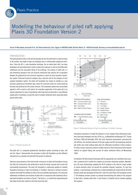
Figure 2: Settlement behavior <strong>of</strong> high-rise buildings in Frankfurt, Germany<br />
Figure 1: Principles <strong>of</strong> piled raft<br />
The piled raft is a composite geotechnical foundation system consisting <strong>of</strong> piles, raft<br />
and soil. Figure 1 demonstrates <strong>the</strong> principles <strong>of</strong> piled raft foundation and <strong>the</strong> different<br />
interactions (e.g. pile/pile and pile/raft) that govern its behavior.<br />
Extensive measurements <strong>of</strong> <strong>the</strong> load transfer mechanism <strong>of</strong> piled raft foundations during<br />
and after <strong>the</strong> construction were performed to verify <strong>the</strong> design concept and to prove <strong>the</strong><br />
serviceability requirements. The piled raft foundation is extensively applied as suitable<br />
foundation technique <strong>of</strong> high-rise buildings in Frankfurt, Germany to achieve economic<br />
solutions that fulfill <strong>the</strong> stability as well as <strong>the</strong> serviceability requirements. The measured<br />
settlements <strong>of</strong> different case histories <strong>of</strong> piled rafts in comparison with traditional raft as<br />
well piled foundation are shown in Figure 2. The factor α L<br />
is a load factor representing <strong>the</strong><br />
load taken by <strong>the</strong> piles relative to <strong>the</strong> total structural load.<br />
Calculation procedures to model <strong>the</strong> behavior <strong>of</strong> such complex three-dimensional problems<br />
have been developed since <strong>the</strong> 1970s (e.g., by Butterfield and Banerjee 1971, Poulos<br />
and Davis 1980 and Randolph 1993). But some important requirements concerning <strong>the</strong><br />
raft stiffness, <strong>the</strong> nonlinear behavior <strong>of</strong> <strong>the</strong> pile support and <strong>the</strong> slip developing along <strong>the</strong><br />
pile shafts even under working loads were not sufficiently considered in <strong>the</strong>se analyses.<br />
For <strong>the</strong>se reasons improved numerical models based on three dimensional finite element<br />
method are applied taking into account all above mentioned effects (El-Mossallamy<br />
1996).<br />
A traditional 3D finite element technique with <strong>the</strong> appropriate soil constitutive laws presents<br />
a powerful tool to model this complex soil-structure interaction problem. Never<strong>the</strong>less,<br />
<strong>the</strong> main disadvantage applying <strong>the</strong> 3D FE analyses is <strong>the</strong> need <strong>of</strong> a huge number<br />
<strong>of</strong> volume elements which can exceed <strong>the</strong> available computer capacities. To cover this<br />
problem, a new technique combined <strong>the</strong> so called embedded pile model with <strong>the</strong> 3D finite<br />
element model was developed by <strong>Plaxis</strong> B.V. under <strong>the</strong> name <strong>Plaxis</strong> 3D Foundation version<br />
2. The following sections present an example demonstrating <strong>the</strong> ability <strong>of</strong> this program<br />
to deal with a complex piled rafts. A case history in Frankfurt will be resolved applying<br />
this program.<br />
10
<strong>Plaxis</strong> Practice<br />
Foundation and subsoil conditions<br />
General information<br />
Height (m) 114<br />
Foundation area (m!) 1930<br />
<strong>Raft</strong> thickness (m) 3.5 - 1.0<br />
Foundation depth (m) -15.75<br />
Groundwater - 6.0<br />
Slenderness ratio 3.5<br />
No <strong>of</strong> piles 25<br />
Pile length (m) 22<br />
Pile diameter (m) 1.3<br />
General information<br />
Height (m) 114<br />
Foundation area (m2) 1930<br />
<strong>Raft</strong> thickness (m) 3.5 - 1.0<br />
Foundation depth (m) -15.75<br />
Groundwater - 6.0<br />
Slenderness ratio 3.5<br />
No <strong>of</strong> piles 25<br />
Pile length (m) 22<br />
Pile diameter (m) 1.3<br />
Figure 3: General layout<br />
Frankfurt subground and methodology<br />
to develop <strong>the</strong> piled raft<br />
Most <strong>of</strong> <strong>the</strong> high-rise buildings in Frankfurt are founded on <strong>the</strong> so-called Frankfurter clay,<br />
which developed 2 to 10 million years ago as a result <strong>of</strong> <strong>the</strong> sedimentation in <strong>the</strong> Tertiary<br />
sea in <strong>the</strong> Mainz basin. In <strong>the</strong> town center, <strong>the</strong> clay layer measures up to 100 meters and<br />
includes limestone banks, lignite coal lenses and layers <strong>of</strong> calcareous sand. The groundwater<br />
level is mostly just above <strong>the</strong> clay surface and circulates in <strong>the</strong> fissured limestone<br />
banks and sand lenses resulting in different confined aquifer pressures. The clay is geologically<br />
overconsolidated through older, already eroded sediments and volcanic rock.<br />
Geometry<br />
The foundation <strong>of</strong> <strong>the</strong> building has a total area <strong>of</strong> about 1930 m². Only 25 large diameter<br />
bored piles were constructed beneath <strong>the</strong> raft as a piled raft foundation. The pile arrangements<br />
are shown in Figure 4. The rafts are 3.5 meters thick in <strong>the</strong> middle and 1.0 m at<br />
<strong>the</strong> edges. The raft base lies at a depth <strong>of</strong> 15.75 meters below <strong>the</strong> soil surface. The piles<br />
where designed with a diameter <strong>of</strong> 1.3 m and a length <strong>of</strong> 22 m. The total working loads<br />
reach about 900 MN.<br />
Example <strong>of</strong> a high-Rise Building<br />
on Frankfurt subsoil<br />
The 120 m building with a 4-storey underground basement has an L shape (Fig. 3) with<br />
a load eccentricity <strong>of</strong> about 7.0 m. Applying <strong>the</strong> concept <strong>of</strong> piled raft foundation it was<br />
possible to construct <strong>the</strong> foundation without settlement joints between <strong>the</strong> tower and<br />
<strong>the</strong> adjacent 4-storey underground garage. The piles were placed eccentrically below <strong>the</strong><br />
tower to balance <strong>the</strong> load eccentricity.<br />
Figure 4: Foundation dimensions and pile arrangement<br />
11
<strong>Plaxis</strong> Practice<br />
<strong>Modelling</strong> <strong>the</strong> behaviour <strong>of</strong> piled raft applying<br />
<strong>Plaxis</strong> 3D Foundation Version 2<br />
Yasser El-Mossallamy, Associate Pr<strong>of</strong>., Ain Shams University, Cairo, Egypt c/o ARCADIS GmbH, Berliner Allee 6, D - 64295 Darmstadt, Germany y.el-mossallamy@arcadis.de<br />
Figure 5: 3D FE-Model<br />
Figure 6: Applied loads<br />
Figure 7: Foundation settlement under working loads<br />
Numerical model<br />
Soil Parameters<br />
The soil stress-strain relationship was modelled applying <strong>the</strong> Hardening soil model. The<br />
main advantage <strong>of</strong> this constitutive law is its ability to consider <strong>the</strong> stress path and its<br />
effect on <strong>the</strong> soil stiffness and its behavior. For <strong>the</strong> concrete piles and raft, a linear elastic<br />
material set was applied using <strong>the</strong> concrete weight and its stiffness. The ultimate skin<br />
friction <strong>of</strong> <strong>the</strong> pile is assumed to start with 60 kPa at <strong>the</strong> pile head and increased with<br />
depth to reach 120 kPa at <strong>the</strong> pile tip. The ultimate pile base resistance was taken equal<br />
to 2.0 MPa.<br />
3D Finite element model<br />
Work-planes are defined. The Work-planes are needed at each level where a discontinuity<br />
in <strong>the</strong> geometry or <strong>the</strong> loading occurs in <strong>the</strong> initial situation or in <strong>the</strong> construction process.<br />
Figure 5 shows <strong>the</strong> applied three dimensional finite element mesh. The main model<br />
geometries are given in figure 6.<br />
Inspect output<br />
The initial conditions should be generated using <strong>the</strong> K 0<br />
-procedure. A value <strong>of</strong> K 0<br />
= 0.8 is<br />
applied to consider <strong>the</strong> effect <strong>of</strong> overconsolidation. The aim <strong>of</strong> <strong>the</strong> calculation is to determine<br />
<strong>the</strong> average settlement <strong>of</strong> <strong>the</strong> rafts under working load (serviceability limit state).<br />
Figure 7 demonstrates <strong>the</strong> raft settlements under working loads.<br />
Settlement <strong>of</strong> about 4 cm is calculated at <strong>the</strong> raft center. This value agrees well with <strong>the</strong><br />
measured value and approves <strong>the</strong> ability <strong>of</strong> <strong>the</strong> three dimensional analyses to predict <strong>the</strong><br />
settlement <strong>of</strong> <strong>the</strong> piled raft as a main part <strong>of</strong> <strong>the</strong> foundation design. Figure 8 shows <strong>the</strong><br />
load distribution among <strong>the</strong> individual piles within <strong>the</strong> pile group. It can be recognized<br />
that <strong>the</strong> contribution <strong>of</strong> <strong>the</strong> edge piles by carrying <strong>the</strong> loads is very small. This is due to<br />
<strong>the</strong> presence <strong>of</strong> <strong>the</strong> outer wall that works also as shoring system, which is modelled as<br />
fully connected with <strong>the</strong> foundation raft. The effect <strong>of</strong> <strong>the</strong> outer walls can be investigated<br />
by applying a new model in which <strong>the</strong> outer walls are not modelled.<br />
12
<strong>Plaxis</strong> Practice<br />
Conclusion and Outlook<br />
The illustrated examples show that understanding <strong>of</strong> <strong>the</strong> effects <strong>of</strong> <strong>the</strong> interaction between<br />
construction and subsoil based on <strong>the</strong> appropriate <strong>the</strong>oretical knowledge and on<br />
experienced application <strong>of</strong> measurement techniques and numerical modelling are <strong>the</strong><br />
necessary qualification for a safe and economic design for such complex foundations.<br />
The piled raft foundation can be modelled using <strong>the</strong> embedded piles that are available in<br />
<strong>Plaxis</strong> 3D foundation. The results should be fur<strong>the</strong>r compared with cases where <strong>the</strong> piles<br />
are modelled using volume elements. There is still need <strong>of</strong> horizontal interface elements<br />
to investigate <strong>the</strong> raft contact stresses in a direct manner. The embedded piles help to<br />
reduce <strong>the</strong> required number <strong>of</strong> elements needed to model <strong>the</strong> complex three dimensional<br />
feature <strong>of</strong> piled rafts. The experience with this model type should be ga<strong>the</strong>red with time<br />
and shared among <strong>the</strong> <strong>Plaxis</strong> users. The effect <strong>of</strong> <strong>the</strong> shoring system on <strong>the</strong> behavior <strong>of</strong><br />
piled raft needs fur<strong>the</strong>r investigation.<br />
Some related references<br />
- Burland, J.B., Broms, B.B., and de Mello, V. (1977) <strong>Behaviour</strong> <strong>of</strong> foundations and structures,<br />
State-<strong>of</strong>-<strong>the</strong>- art report, Proc. 9th ICSMFE Tokyo, vol. 2, 495 - 546<br />
- Butterfield, R., and Banerjee, P.K. (1971) "The problem <strong>of</strong> pile group-pile cap interaction."<br />
Géotechnique, Vol. 21, No. 2, pp. 135-142.<br />
- DIN 1054-100 (2005) Baugrund: Sicherheitsnachweis im Erd- und Grundbau<br />
- Dürrwang, R., El-Mossallamy, Y. und Reininger-Behrenroth, M.(2007) Neue Erkenntnisse<br />
zum Verformungsverhalten des Frankfurter Tones, Bautechnik, Vol.3, 190-192<br />
- El-Mossallamy, Y. (1996) Ein Berechnungsmodell zum Tragverhalten der kombinierten<br />
Pfahl-Plattengründung., Dissertation, Fachbereich Bauingenieur-wesen der Technischen<br />
Hochschule Darmstadt<br />
- El-Mossallamy, Y., Lutz, B., and Richter, Th. (2006) Innovative application and design<br />
<strong>of</strong> piled raft foundation. 10th International Conference on Piling and Deep Foundations,<br />
(31 May - 2 June 2006), Amsterdam, Ne<strong>the</strong>rlands<br />
Outer piles<br />
- El-Mossalamy, Y., El-Nahhas, F. and Essawy, A. (2006) Innovative Use <strong>of</strong> <strong>Piled</strong> <strong>Raft</strong><br />
Foundation to Optimize <strong>the</strong> Design <strong>of</strong> High-Rise Buildings. 10th Arab Structural Engineering<br />
Conference, 13-15 November 2006, Kuwait<br />
- El-Mossallamy, Y (2007) <strong>Piled</strong> raft foundation in Frankfurt clay. Validation manual,<br />
<strong>Plaxis</strong> 3D Foundation, Version 2<br />
- Franke, E.; El-Mossallamy, Y.; and Wittmann, P.(2000) Calculation methods for raft<br />
foundations in Germany. Design applications <strong>of</strong> raft foundation and ground slabs, Edited<br />
by Hemsley, Published by Thomas Telford Ltd, London, 2000, p.p.283-322<br />
- Hanisch, J., Katzenbach, R., und König, G. 2002. Kombinierte Pfahl-Plattengründung,<br />
In Zusammenarbeit mit dem Arbeitskreis „Pfähle“ der Deutschen Gesellschaft für Geotechnik<br />
e.V. (DGGT), Ernst & Sohn.<br />
- Poulos, H.G., and Davis, E.H. (1980) Pile Foundation Analysis and Design. Wiley, New<br />
York.<br />
Middle piles<br />
- Randolph, M.F. and Clancy, P. (1993) Efficient design <strong>of</strong> piled rafts. Proc. 2nd Int. Seminar,<br />
Deep foundation, Ghent, 119-130.<br />
Figure 8: Results <strong>of</strong> normal force distribution along all piles<br />
13


