Aquadyne(C) Bead Filtration Systems - Koi-Stuff Koi-Stuff
Aquadyne(C) Bead Filtration Systems - Koi-Stuff Koi-Stuff
Aquadyne(C) Bead Filtration Systems - Koi-Stuff Koi-Stuff

You also want an ePaper? Increase the reach of your titles
YUMPU automatically turns print PDFs into web optimized ePapers that Google loves.
<strong>Aquadyne</strong>(C) <strong>Bead</strong> <strong>Filtration</strong> <strong>Systems</strong><br />
Dive in and see what the future offers in no hassles,<br />
no complaints low maintenance filtration.<br />
Never Clean Messy Filter Pads Again!<br />
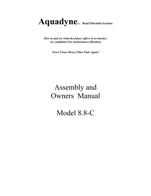
Assembly and<br />
Owners Manual<br />
Model 8.8-C
Dynamax Riser Valve<br />
Return to pond<br />
From pump<br />
Model 8.8-C Basic Configuration<br />
Overhead View Diagram 1<br />
<strong>Aquadyne</strong><br />
Waste Line<br />
Top Cap<br />
Clear Vent Cap<br />
Sludge Valve<br />
Side View Diagram 2<br />
Clear relief cap<br />
Cap Gasket<br />
Main Cap<br />
Main Cap Gasket<br />
Dynamax Blower<br />
<strong>Aquadyne</strong><br />
Relief Cap Nut<br />
Multiport Control Head<br />
Sludge Valve
Main Filter Body Assembly - Model 8.8 with Blower<br />
Unpacking and Installation Instructions<br />
Refer to the Schematic Diagrams for a Visual Reference<br />
1. First carefully unpack all boxes.<br />
(Main filter tank, <strong>Bead</strong> Media, Multiport Control Head, and the Misc. Assembly Parts Box.)<br />
2. Gently place the main tank on its side with the black bulkheads for the multiport valve<br />
attachment facing up so not to strain the column attachment on the interior of the tank.<br />
Install the sludge drain valve into the bottom tank bulkhead with the sludge drain pipe<br />
passing through the base. Teflon tape has already been applied to the threads for you.<br />
Be sure the sludge valve is in the closed position.<br />
3. Gently upright the main tank and place the tank into its relative permanent position.<br />
4. With a garden hose add about 15 gallons (12 inches) of water into the tank.<br />
5. Pour all included bead media into the top opening of the main tank, allowing the media to<br />
flow evenly around the central column<br />
6. Install the Clear Relief Cap into the center of the Main Tank Cap making sure that the<br />
cap gasket is in place. Screw the Relief Cap Nut onto the Clear Relief Cap on the<br />
underside of the Main Tank Cap. Tighten snugly with pliers.<br />
7. Install the Main Tank Cap into the top access hole in the Main Tank, making sure that the<br />
included large square gasket is properly seated into the main cap.<br />
8. Glue the Dynamax Riser Valve onto the 45 degree fitting attached to the preinstalled<br />
blower bulkhead fitting. Install in a vertical position with the red handle in a favorable<br />
position for easy manipulation. Screw the Dynamax blower on top of the riser valve.<br />
8. Next install the Multiport Control Valve onto the black matched bulkhead fittings<br />
protruding from the Main Tank at its center. Hand tighten the multiport valve unions<br />
only, as they have internal slip o-ringseals that do not require overtightening.<br />
9. Attach your Pump, Pond Return, and Waste lines, into their appropriate positions on the<br />
Multiport Control Valve. (If you wish, place unions in these lines in the event that you<br />
ever need to remove the control valve without disturbing any peripheral plumbing lines.)
Clear pressure relief assy.<br />
Black Cap<br />
Column Stabilizer<br />
Upper Tube<br />
Lower Tube<br />
Laterals<br />
<strong>Aquadyne</strong><br />
Model 8.8<br />
Column Stabilizer<br />
Starting your <strong>Aquadyne</strong> 8.8-C for the first time:<br />
1. Open your pump leaf trap and fill the reservior with water. It is recommended that you<br />
install a “swing check valve” in the suction line to speed the priming process. Swing<br />
checks valves are mandatory for non-selfprining pumps.<br />
2. Be sure that the blower valve is closed.<br />
3. Turn on your pump with the Multiport control Valve in the Rinse position.<br />
This will purge any manufacturing dust out of the waste line once the filter has filled with<br />
water. Note: It may take severl minutes to fill the Main Tank with water when first<br />
starting up your filter. The Main Tank holds about 60 gallons of water.<br />
4. Once water has discharged from the waste line for 30 seconds, return the Main Control<br />
Valve to the Filter position. You are now in normal filtration mode and filtering the pond<br />
water. Although solids removal will take effect in a short period of time. Biological<br />
cycling of the media may take 6 to 12 weeks, after which time ammonia and nitrite<br />
removal begin to stabilize.<br />
It is hard to resist wanting to backwash your filter, especially for the first few times. However, it is important that<br />
fish waste and other debris be allowed to accumulate in the filter media so that the beneficial biological bacteria can<br />
established a healthy colony.<br />
Backwashing your <strong>Aquadyne</strong> 8.8-C for the first time:
The big day is finally here! It is time to backwash your model 1.1 for the first time.<br />
1. With your pump motor running, change the control head position to Backwash momentarily, then to rinse.<br />
2. Shut off the main pump. The main pump should not operate while the Dynamax blower is running.<br />
3. Open the Dynamax blower control valve, and switch on the blower.<br />
4. At first about 3 to 5 gallons of water will discharge from the waste line, followed by bursts of air produced by<br />
the washing action of the air escaping from the main tank during blower operation.<br />
5. Allow the blower on the model 8.8 to run for at lease 5 minutes to effectively preclean the bead media.<br />
6. Switch the blower off, and close the blower control valve.<br />
7. Set the main control head to the backwash position.<br />
8. Turn the main pump back on.<br />
9. Once the discharge begins to run clear from the backwash cycle, switch the control head to the rinse position.<br />
The water will run clear in a few seconds. Once clear, return the control head back to the filter position.<br />
10. After backwashing, and once the control head is returned to the filter position, always open the sludge valve<br />
located at the bottom of the filter for a few seconds to purge any heavy solids from the bottom of the tank.<br />
Opening the sludge valve during the backwash cycle is not recommended. You may loose bead media<br />
through the sludge valve during the backwash cycle.<br />
If while using the Dynamax to air wash the bead media, and you notice that you can not hear the beads swishing<br />
around in the tank, you man need to rotate the main control head back and forth between backwash and rinse two<br />
or three times with the main pump running, before running the Dynamax blower system. This will “unload” the<br />
media that is crowding the laterals and not allowing effective air escape. Do not allow the handle to cross<br />
over the “closed” position while performing any control head position changes while the pump is running.<br />
Damage may occur.<br />
Backwashing is recommended weekly. With the Dynamax you can go 2,3, or 4 weeks depending on load.
<strong>Aquadyne</strong> 8.8 Control Head Functions:<br />
Congratulations on your assembly of the <strong>Aquadyne</strong> <strong>Bead</strong> Filter. You are now ready to enjoy one of the<br />
most maintainence free and well supported biological and mechanical filtration systems ever produced.<br />
First lets get acquainted with the features of the main control head.<br />
The “Filter” position is used for the normal flow of water through the filter system.<br />
The “Backwash” position is used to backflush waste and debris from the filter.<br />
The “Rinse” position is used to pre-rinse the bead media prior to returning to the filter mode, which<br />
prevents the return of any harmful debris back to the pond environment.<br />
The “Rinse” position is also used to vent air from the Dynamax blower when it is in use.<br />
The “Recirculate” position is used to bypass the normal flow of water away from the filter media while<br />
maintaining pond circulation. This is beneficial when medicating the pond with agents that may be<br />
harmful to the beneficial bacterial colonies which reside in the bead media.<br />
The “Waste” position also bypasses the filter media. Water flows from the pump, through the control<br />
head and out to waste. This position can be beneficial to diagnose any water flow problems, or to simply<br />
drain the pond. It can also be used to discharge vacuum waste, if you attach a vacuum hose to your pump<br />
suction.<br />
The “Closed” position stops all flow of water through the control head. This position has little use<br />
except in a case where the filter is installed below the water level, it will function as a shutoff valve to<br />
prevent water backflowing through the pump strainer basket if the lid is removed. If you change control<br />
head positions while the pump is running, and the handle accidentally slips into the closed position,<br />
damage may result to your filter. While it is acceptable to change the control handle position while the<br />
pump is running, always rotate the handle in a direction away from the closed position.<br />
The “Winter” position is a raised notch which opens all ports of the control head and allows water to<br />
drain from the control head and column to prevent freezing and damage. The bottom sludge drain must<br />
also be slightly opened to allow water to drain from the main tank body and internal column.<br />
Pump<br />
In<br />
Rinse<br />
Filter<br />
Waste<br />
Waste<br />
Out<br />
Winter<br />
Return<br />
to Pond<br />
Recirculate<br />
Closed<br />
Backwash
<strong>Aquadyne</strong> <strong>Bead</strong> <strong>Filtration</strong> <strong>Systems</strong><br />
Model 8.8-C Internal Layout<br />
Internal View Diagram 3<br />
Laterals<br />
Water Transfer Tube<br />
Air Check Valve<br />
and Internal<br />
Riser Assembly<br />
Dynamax Air Diffuser<br />
Main Diffuser Column<br />
<strong>Bead</strong> Media<br />
Main Diffuser Column<br />
Sedimentation Area<br />
Dynamax Air Diffuser<br />
Internal View With Media Diagram 4
Internal Disassembly Instructions<br />
If there is ever a need to remove the internal column of a Model 8.8 this drawing will aid you in the<br />
proper alignment of internal components.<br />
1. Remove and reuse the 4 original laterals protruding from the upper side of the column. When<br />
reinstalling the laterals into the new column, be sure that the slots in the laterals are mostly vertical.<br />
2. With a black permanent marker, mark the tubes and the column fittings with both a bepth mark, and a<br />
rotational index mark for later reassembly.<br />
3. Remove the two stainless set screws that secure the main column to the upper and lower water transfer<br />
tubes. With a mallet, strike the front of the column, between the transfer tubes to force the column<br />
connecting fittings off of the tubes, liberating the central column.<br />
4. Remove the column from the tank. Remove the upper and lower tubes by turning in a<br />
counter-clockwise direction. LABEL the tubes with a marker as either the UPPER or LOWER TUBE<br />
for reassembly later<br />
5. If you ever should have to remove one or both of the black multiport bulkhead fittings, (see diagram 5<br />
for an illustrative view of the bulkheads orientation) use care when assembling or disassembling this<br />
bulkhead. Its replacement cost is about $50. of the Screw the 2 new horizontal connecting tubes onto<br />
the black side mount control head fittings attached onto the tank, HAND TIGHTEN the tubes for now,<br />
being sure that the tubes are installed in the correct upper and lower positions as indicated by black<br />
marker on the tubes.<br />
6. Reverse the order of disassembly for reassembly.<br />
7. When reinserting the center column into the tank, manually slip the column fittings over the upper and<br />
lower water transfer tubes and with a hammer or mallet strike the column firmly on the opposite side<br />
of the column from the horizontal tubes. (See Diagram) Drive the column onto the tubes until the<br />
black ring drawn on the horizontal tube is almost flush with the attaching fitting on the column. This<br />
will assure proper depth seating into the fittings and set screw realignment. (See Diagram) Do not<br />
worry about breaking the column. You will not be able to strike it hard enough to break it inside the<br />
tank. You will find that it will take very little tappping to seat it to the proper level.<br />
8. Now insert a pair of channel lock pliers, pipe wrench, or similar holding device into the tank and rotate<br />
the horizontal upper and lower tubes in the tightening direction until the two screw hole index<br />
alignment marks match identically with their opposing marks on the two separate tubes. (See<br />
Diagram) Grasp the tubes with the pliers near the tank inside and rotate them in a tightening direction.<br />
This will align the pre-drilled set screw holes in the pipes and allow you to screw the included<br />
stainless set screws into the horizontal pipes, therefore preventing the pipes from ever moving<br />
accidentally, and causing beads to discharge into your pond. If you do not align the marks correctly<br />
the set screws will not pass through both holes properly.<br />
8. Re-install the laterals into the top of the central column which is now remounted into the tank,<br />
assuring that the laterals are a snug hand tight. If possible rotate the laterals slightly tighter or looser<br />
so that the slots in the pipe run as near to vertical as possible for best performance.
Diagram 5<br />
Disassembly / Assembly<br />
Upper Tube Female Threads<br />
Black marker<br />
depth index<br />
Laterals<br />
Set screw hole<br />
index mark<br />
Black Side Mount Fittings<br />
Upper Tube<br />
Lower Tube<br />
Mallet or<br />
hammer impact<br />
area<br />
Lower Tube Female Threads<br />
Set Screw<br />
Diagram 6<br />
Transfer tube<br />
alignment with<br />
column fittings<br />
Correct Alignment<br />
Both upper and lower tubes<br />
Set screw hole index mark<br />
Set screw hole<br />
Female Adapter<br />
Incorrect Alignment<br />
Both upper and lower tubes<br />
Set screw hole index mark<br />
Set screw hole<br />
Female Adapter
Tank Bulkhead Configuration<br />
for Multiport Valve Bulkhead Fittings<br />
It would be a rare occasion for anyone to have to manipulate this bulkhead fitting. However, we are including an<br />
illustrated parts breakdown of this component for a point of reference.<br />
Diagram 7<br />
Proper vertical alignment<br />
of tool stud divits<br />
Keyway should be on top<br />
to maintain correct parabolic<br />
contact of fittings to the tank<br />
wall<br />
Pump<br />
In<br />
Return<br />
to Pond<br />
Vertical<br />
Thin Parabolic Ring Seal<br />
Outer Parabolic Ring<br />
Main Oring Seal<br />
Tank Wall<br />
Rear Nut<br />
Inner Parabolic Ring<br />
Due to the necessity of maintaining vertical alignment, the tool stud divits<br />
must remain vertical at all times of both tightening and loosening. Tighten by<br />
turning the rear nut only. This procedure usually requires two persons. One to<br />
hold vertical alignment with the tool divits and the other to tighten the nut.
During the filtration cycle, water flows upward through the bead media exposing the ammonia and nitrite laden<br />
water to billions of beneficial nitrifying bacteria which grow on the surface areas of the bead media. At the same<br />
time the bead media is capturing fine particulate matter such as fish waste and other light particles and allows clean<br />
water to return to the pond. Heavy waste particles such as mud and large waste debris to settle into the bottom of<br />
the main tank in the sedimentation area.<br />
During the backwash cycle the water flow is reversed and the beads are decompressed from their packed<br />
state in the filter cyle. Gravity, together with forced water flow causes the waste and debris to be backwashed out of<br />
the media and washed out the lower grate screen to the waste line. As the water begins to clear up in the waste<br />
water sight glass, you will reposition the control handle to the rinse cycle. This will rinse any remaining debris from<br />
the top of the media. As soon as the sight glass runs reasonably clear in the rinse cycle, you simply return the<br />
control handle to the filter position and you are finished.<br />
Draining Your Pond and Water Changes:<br />
Typically, the backwashing process will discharge enough water over a couple of backwashings to satisfy your<br />
water change needs. However, if you need to remove large sums of water from your pond for cleaning or other<br />
purposes, simply rotate the control head handle to the WASTE position and the pond water will be drained to waste<br />
without passing through the filter as long as the pump or suction line is under water. It is not a good idea to drain<br />
your pond in the backwash cycle, as it will cause excessive loss of beneficial bacteria from bead friction.<br />
Medicating Your Pond:<br />
At times it may be necessary to add medications to your pond that will harm the beneficial bacteria in your<br />
biological filter. In this case you will simply position the top control handle to the RECIRC. position. Always<br />
perform a BACKWASH cycle before closing off your filter from circulation. This will clear the filter of waste and<br />
prevent it from becoming septic. Before returning the filter to normal operation, backwash the filter again to<br />
discharge any septic water that may have formed in the filter while being bypassed. RECIRC. allows the water<br />
coming from the pump to bypass the filter completely and recirculate to the pond without passing through the filter<br />
media, and thus not killing the biological capacity of your filter. The beneficial bacteria should be able to survive in<br />
the closed system for many weeks. When you return your filter to normal operation after an extended period of<br />
medicating, the capacity of the filter may be stunted for a short time, but should catch back up with the demand of<br />
your pond within a couple of days. Always perform a 50% water change after medicating your pond.<br />
Winterizing Your Filter:<br />
Many people find is necessary to shut their pumps off in the winter time. If this is the case you will need to<br />
winterize your pump and filter system. First, perform a complete backwash cycle and shut your pump off. Next,<br />
drain the main tank by placing the main control head in the “Winter” position and open the sludge drain and allow<br />
the water to trickle out. Do not open the sludge drain fully and leave the filter unattended or the bead media will<br />
surely run out of the tank. However, it is acceptable to open the sludge drain fully to accelerate the draining process<br />
if you are there to close the valve to a trickle at the first sight of beads escaping. You may remove the winterizing<br />
cap if you wish. However, due to the sludge drain being post factory installed lower than the original winterize cap,<br />
the cap no longer serves as a necessary component of the filter. Again, do not fully open the sludge drain valve to<br />
drain the tank water unattended as the beads will wash out by the hundreds. Once the tank is drained leave the<br />
valve cracked just a little to prevent any water from freezing in the pipe. Do not be alarmed if on occasion you<br />
loose a few beads from the sludge lower waste drain. This is normal as on occasion some beads will be trapped in<br />
clumps of waste that will discharge through the drain. You could loose several pounds of beads from most sizes<br />
before you ever affected the filters biological capacity. Replacement beads are available if you should ever want to<br />
top off your filter, but be cautious not to add more than the specified weight for your filter, as the filter has been<br />
designed to function properly with a specific quantity of beads.
<strong>Bead</strong> Capacity Minimum by Depth Measure:<br />
Models .60 and .60-B --- 8.5 inches<br />
Models 1.1 and 1.1B --- 10.5 inches<br />
Models 2.2 and 2.2-B --- 13.5 inches<br />
Model 4.4 --- 15.5 inches<br />
<strong>Bead</strong> depth can be measured by two methods. #1 remove the control head and drain the main<br />
tank as if winterizing. Once the water is removed, simply insert a measuring device to the bottom<br />
of the tank and measure.<br />
#2 Remove the control head from the main tank and fill the tank with water until the beads float<br />
2 to 3 inches below the tank opening. Insert a measuring device and reach into the beads and<br />
guide the end of the measuring device level with the bottom of the floating bead media. Take the<br />
bead depth reading from the surface of the media at the tank opening.<br />
Vacation<br />
If you plan to be away from your pond for an extended period of time, there is no need to worry<br />
about backwashing your filter while you are away unless your pond is heavily stocked and<br />
requires more frequent cleaning. The filter is designed so that there is little resistance to water<br />
flow through the media and diffuser column. If you are normally backwashing once per week<br />
and not getting an extreme amount of dirt waste from the filter, you can leave you filter running<br />
for three to four weeks unattended, depending on the filter size and fish load, but you will want<br />
to perform a very good backwash upon returning to assure that the filter is clean.<br />
There is a word of caution: When leaving your filter for long periods of time (weeks), be sure<br />
to buffer your pond water. The <strong>Aquadyne</strong> filter together with the decomposition bacteria in your<br />
filter are so efficient that a pH shift may occur if your water is not buffered.
Control Head Parts Layout<br />
This control head layout is not an exact 8.8 duplication, but most all<br />
components are the same as illustrated.<br />
Control Position Pointer<br />
Steel Handle Pin<br />
Stainless Machine<br />
Screw 6 each<br />
Flow Control Stem<br />
(hub and stem are one piece)<br />
Main Hub Spring<br />
Open Hub port<br />
Flow Control<br />
Hub and Stem<br />
Control Handle<br />
MainCap<br />
Main Cap Indexing<br />
Divot<br />
Main Cap Oring<br />
Plastic Split Washer<br />
Rubber Oring<br />
2 each<br />
Steel Flat Washer<br />
2 each<br />
Main Cap Indexing<br />
Stud<br />
Pressure Guage<br />
Pump Line In<br />
Control Head Body<br />
Return Line Out<br />
to UV or Pond<br />
Waste Line Out<br />
Pump<br />
In<br />
Rinse<br />
Filter<br />
Waste<br />
Waste<br />
Out<br />
Winter<br />
Return<br />
to Pond<br />
Recirculate<br />
Closed<br />
Backwash
Filter Care and Maintenance<br />
While typically you can expect to receive a lifetime of trouble free service from your <strong>Aquadyne</strong> system, there are a<br />
couple of service related procedures that you may wish to perform over the years, although for the most part, there<br />
are no major service concerns related to the systems.<br />
1. Rubber O-ring Lubrication may be necessary if the main control handle becomes difficult to reposition.<br />
Over the years the factory lubrication may dry out on the two small orings located on the flow control stem which<br />
require lubrication. To perform this procedure, first use a pin driver to remove the Steel Handle Pin from the<br />
Control Handle. (A pin driver can be any blunt steel rod which has a smaller diameter than the rod itself, which can<br />
be driven through the control handle.) Next remove the Stainless Machine Screws or bolts which hold down the<br />
Main Cap to the Control Head Body and remove the Main Cap assembly from the control head body. Grasp the<br />
Main Cap in one hand and the Flow Control Hub in the other and twist while pulling them apart from each other.<br />
This will expose the two rubber o-ring located on the Flow control Stem. Lubricate the two o-rings liberally with a<br />
silicone based or similar o-ring lubricant. It is not necessary to remove the o-rings from the stem unless they are<br />
leaking or broken. If it is necessary to remove the o-rings, remove the lower o-ring first, being careful not to scratch<br />
or gouge the inner surfaces of the o-ring seat with a sharp object. Then remove the upper o-ring and split washer.<br />
When reinstalling the o-rings, replace the upper o-ring and split washer first and the lower o-ring last. At this time,<br />
remove, clean, and lubricate the Main Cap O-ring before reassembly. Re-insert the Main Stem and Hub assembly<br />
into the Main Cap and be sure that the Open Hub Port in the Main Hub is aligned with the Filter Position indicated<br />
in writing on the Main Cap label. Insert the re-assembled Main Cap assembly into the Control Head Body, being<br />
sure to align the Main Cap Indexing Divot with the Main Cap Indexing Stud on the Control Head Body. Re-insert<br />
the Stainless Machine Screws or bolts into the Main Cap and hand tighten in a cross over pattern as you would the<br />
lug nuts on an automotive wheel. This will assure a uniformly seated Main Cap assembly. Place the Control Handle<br />
onto the Flow Control Stem with the Control Position Pointer facing the Filter Position indicated in writing on the<br />
Main Cap label. If the Open Hub Port and the Control Position Pointer are not aligned in this fashion the filter will<br />
not work properly when returned to service. Lasty, re-insert the Steel Handle Pin into the Control Handle and drive<br />
it flush on both sides. If you ever experience a leak from between the main control head body and the filter tank<br />
it is likely that the Main Control Head O-ring Gasket either needs lubricating or replacing. The Flow Control Hub<br />
Main Seal is a permanent seal which is molded into the Flow Control Hub and Stem assembly on models .60<br />
through 2.2-B with 1 ½ inch control heads. No lubrication or service is necessary on this seal. If this seal is ever<br />
cut or damaged, simply replace the Flow Control Hub and Stem Assembly.<br />
2. Replacement Parts are available for all filter models factory direct as most dealers do not stock replacement<br />
parts due to the fact that out of thousands of filter sales, there have been so few replacement parts ever requested.<br />
The most requested relacement part is the Main Control Head O-ring Gasket of which we have shiped about 10 to<br />
15 gaskets.<br />
It is the policy of <strong>Aquadyne</strong> to make available non-warrantied or warranty-waived replacement parts at<br />
factory cost plus shipping. It is our desire to make your <strong>Aquadyne</strong> experience as trouble free and future cost<br />
effective as possible.<br />
<strong>Aquadyne</strong> filters are warranted for life to the original purchaser of the filter. This warranty covers the<br />
control head body, the <strong>Aquadyne</strong> central diffuser column, the main tank body, blower riser, and sludge drain<br />
components. This warranty DOES NOT include damage resulting from freeze, misuse, mishandling; rubber<br />
or electrical components.
Questions Most Asked<br />
Over the past year I have been asked a set of questions that seem to be repeating<br />
themselves, so I thought I would answer them for you ahead of time. So here they are in advance,<br />
with answers that you can sink your teeth into.<br />
Q: We have clear water, but the fish swimming around the bottom, keep sediment particles<br />
floating around in the pond which cloud the water and never seem to go away.<br />
A: One of the wonderful benefits of the <strong>Aquadyne</strong> systems is that they will remove all of those<br />
micro-fine particles from your pond water. After your <strong>Aquadyne</strong> filter cycles (when the beneficial<br />
bacteria is established), the bacteria creates a thin bacterial colony on each and every one of the thousands<br />
of beads. This bacteria is Nitrosomonas and Nitrobacter, which consumes the Ammonia and Nitrite waste<br />
that your fish produce, These bacteria also serve another purpose as well. If you have ever seen a Sea<br />
Anemone, they have small finger like fronds that extend out to grab particles of food from the ocean. In<br />
much the same way by comparison, the bacteria will trap the very fine particles that are floating around in<br />
your pond and cause the particles to stick to the bacteria coated beads, where it stays until you backwash<br />
it off.<br />
Q: How often do you have to clean the <strong>Aquadyne</strong> system?<br />
A: The <strong>Aquadyne</strong> system should typically be backwashed about once per week. If you have a heavy<br />
fish load in your pond, you may need to backwash twice weekly. Either way, the typical backwash cycle<br />
takes less than five minutes, and you never get your hands wet.<br />
Q: Can you over backwash the <strong>Aquadyne</strong> system?<br />
A: Yes you can. The aquadyne system needs to be backwashed as little as possible for it to function<br />
properly, yet you don’t want to wait weeks between washings. If you backwash the system too often, you<br />
can cause excessive damage to the bacterial colonies that are growing on the beads. During a backwash<br />
the beads rub together as they release the dirt and debris that they have trapped on their surfaces. If you<br />
backwash too often, the dirt and debris will not have a chance to thicken on the beads surface for optimal<br />
filtering. Also, if the filter is left in the backwash position for longer than is necessary to discharge the<br />
waste products, the rolling of the beads that is going on inside the filter can actually kill or severely stunt<br />
the bacterias effectiveness to consume waste for a short time. If you need to drain your pond for any<br />
reason, do so with the control handle in the WASTE position. This will drain your pond to the intake<br />
level of your pump or foot valve, without passing the water through the filter media.<br />
Q: What happens if you do not backwash the <strong>Aquadyne</strong> system for up to a month?<br />
A: Due to the design and size of the Central Diffuser Column, it is virtually impossible for the filter<br />
to get so clogged that the water flow would actually stop. If the filter system did clog and the media was<br />
completely full of debris, the water would side slip the central diffuser column and exit the filter,<br />
bypassing the clogged media and avoiding pump damage. All other bead systems on the market use small<br />
transfer and diffuser tubes inside their bodies, which number one, cause flow restrictions (whether they<br />
admit it or not), (remember the fuzzy logic of friction loss in small piping). The central diffuser column<br />
in the <strong>Aquadyne</strong> is a whopping 6 inches, with no restricting elbows of any kind in the filter chamber.<br />
And number two, many of the other systems have a maximum operating pressure of only 15 PSI. What<br />
good is that if your filter clogs. Even most weenie pumps that would operate a bead system can pump<br />
over 15 PSI when dead headed. The result is that you will blow the spin welded fittings out of the ends of<br />
other polyethylene filters. All models of our <strong>Aquadyne</strong> systems have a whopping 50 PSI pressure rating
from the factory and no “spin welded” fixtures. Even our Sludge Valve bulkhead is schedule 80 PVC<br />
(overkill!) By example of pressure, the flow restriction of the <strong>Aquadyne</strong> system is so low that you would<br />
have to use a pump of several horsepower to attain anything close to 50 PSI. If your filter runs for a<br />
month without a backwash, you can with every confidence, perform an advanced backwash to dislodge<br />
and discharge the debris. Only in the case of a severe clog would you have to spend 15 minutes to<br />
remove the control head, stir the beads through the generous 7” opening, reattach the control head, and<br />
backwash.<br />
Q: Do you ever have to replace the bead media inside an <strong>Aquadyne</strong> system?<br />
A: No, Under the normal use for which the <strong>Aquadyne</strong> system is intended, the beads will last a<br />
lifetime. They are made of a very strong and durable polyethylene material which will not break down.<br />
On occasion, you may notice that you loose a few beads through the sludge drain, but you would have to<br />
loose several pounds of beads before the systems performance even started to weaken. If for any reason<br />
you loose a significant amount of beads, they are quite cheap to replace.<br />
Q: How much power does the system use?<br />
A: None, the <strong>Aquadyne</strong> system is totally passive in its functions. The only power that you will use<br />
is the power that it takes to run your pump which you would have running regardless.<br />
Q: We turn off our pump in the winter. Does this affect the <strong>Aquadyne</strong> system?<br />
A: Yes and No. If you turn off your pump for the winter, you will need to winterize the filter and<br />
pump (if external). First you will give the filter a good backwashing. Then you will drain the filter body<br />
and control head by placing the control handle between any two functions and slightly opening the slu dge<br />
drain in the bottom of the tank to allow the water to trickle out without loosing any bead media. The<br />
winterize cap that is located just above the sludge drain serves no purpose to the system as it is a product<br />
of the tanks original design. It can be removed, but is an ineffecient as the sludge drain is much lower in<br />
the tank and will allow more water to be drained for the purpose of winterizing. If you leave the water in<br />
the filter, the filter may freeze solid and burst the tank which is not covered by warranty.<br />
Q: Will the beneficial bacteria die in our filter if we turn the system off?<br />
A: Some of the bacteria will die off if the filter is left to sit without circulation, because there is no<br />
food in the form of waste or life giving oxygen coming through the filter to make them thrive. Also, if<br />
the beneficial bacteria do not get oxygenated, they produce carbonic acid which can cause a pH shift in an<br />
unstable enviromnent, if drained, and allowed to sit all winter there will be enough of the bacteria<br />
systemic within the pond to reseed the filter quickly the following season. Always perform a backwash<br />
and rinse cycle after the filter has been sitting idle, even for a few days. This will clear any septic waste<br />
or carbonic acid, that has formed while the filter was off.<br />
Q: If we medicate our pond, and use the RECIRCULATE mode to bypass the filter, will the<br />
medicine not kill the bacteria in the filter, once we return the filter to the regular filter<br />
position?<br />
A: Most medications biodegrade or evaporate at different rates during and after treatments.<br />
Depending on the medication used, it is always advisable to make at least a 50% water change after a<br />
medical treatment. If it is not cost prohibitive, due to having to replace thousands of gallons of water, a<br />
80% water change is ideal. A 50 to 80% water change will greatly reduce any hazardous effect that a<br />
medication might have on your filter, with few exceptions. Even if your filter is exposed to most
medications, it will only suffer a temporary slump for a couple of days. Beneficial bacterias reproduce by<br />
the billions per day, and it doesn’t take long to re-establish a healthy colony.<br />
Q: It seems that it would take quite a bit of water to backwash the filter.<br />
A: I love this question! Not that I am going to tell you that it only takes a cup full. But rather to<br />
illustrate the all important water change that most people never provide for their fish. By appropriate<br />
measure, each different size of <strong>Aquadyne</strong> filter requires different amounts of water to perform a cleaning<br />
cycle. I am going to first say that each system requires less water to backwash than you should already be<br />
draining to give your fish a fresh drink. To put it simply, you should always change at least 10% of your<br />
pond water each week, filter or no filter. Fresh water is loaded with minerals and elements that are<br />
critical for your fishes physical health. By comparison, we too need the minerals and elements that are in<br />
water, so that our bodies can remain healthy and nourished. If you do not perform periodic water changes<br />
the fish will absorb all of the available minerals and there will be none left to continue supplementing<br />
their health. Remember how our bodies need calcium, iron, magnesium, zinc, etc. Fish are no different.<br />
Typically, you will only loose an inch or two of water from your during a backwash cycle. That will<br />
likely represent only a 5% water change, so it will not hurt to be a little generous and use a little extra<br />
water during a backwash, your fish will appreciate it.<br />
Thank you for purchasing an <strong>Aquadyne</strong> <strong>Bead</strong> <strong>Filtration</strong> System. We have been told time after time by<br />
many of you that you have really done a lot of research in the marketplace to determine which<br />
manufacturers filter to purchase for your pond environment, and we are very pleased that you have<br />
chosen us to fulfil your needs. We are very respectful that you had the ultimate decision making ability to<br />
choose one of several filters available, and we will diligently stand behind you in support of your efforts<br />
to have a healthy, and as maintenance free pond environment as possible.<br />
Sincerely,<br />
Greg Crane