Technical Service Bulletin - Hyundai Canada
Technical Service Bulletin - Hyundai Canada
Technical Service Bulletin - Hyundai Canada

You also want an ePaper? Increase the reach of your titles
YUMPU automatically turns print PDFs into web optimized ePapers that Google loves.
SUBJECT<br />
<strong>Technical</strong> <strong>Service</strong><br />
<strong>Bulletin</strong><br />
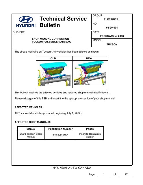
SHOP MANUAL CORRECTION –<br />
TUCSON PASSENGER AIR BAG<br />
GROUP<br />
ELECTRICAL<br />
NO.<br />
08-90-001<br />
DATE<br />
FEBRUARY 4, 2008<br />
MODEL<br />
TUCSON<br />
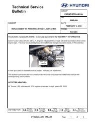
The airbag lead wire on Tucson (JM) vehicles has been deleted as shown.<br />
OLD<br />
NEW<br />
This bulletin outlines the affected vehicles and required shop manual modifications.<br />
Please all pages of this TSB and insert it to the appropriate section of your shop manual.<br />
AFFECTED VEHICLES:<br />
All Tucson (JM) vehicles produced beginning July 1, 2007~<br />
AFFECTED SHOP MANUALS:<br />
Manual Publication Number Pages<br />
2008 Tucson Shop<br />
Manual<br />
A2ES-EU70D<br />
Insert to Restraints<br />
Section<br />
HYUNDAI AUTO CANADA<br />
Page 1 of 27
Restraints<br />
GENERAL<br />
TROUBLESHOOTING<br />
AIR BAG SYSTEM (SRS)
RT -2<br />
GENERAL<br />
RESTRAINTS<br />
SPECIAL TOOLS<br />
EC41D288<br />
Tool (Number and name) Illustration Use<br />
0957A-34100A<br />
Deployment tool<br />
Airbag deployment tool<br />
DAB, PAB: 0957A-38510<br />
BPT: 0957A-38500<br />
SAB, CAB: 0957A-3F100<br />
ERHA010A<br />
0957A-38200<br />
Dummy<br />
Simulator to check the resistance<br />
of each wiring harness<br />
Dummy adapter<br />
DAB, PAB, BPT: 0957A-1C000<br />
SAB, CAB: 0957A-3F000<br />
ERHA010C<br />
0957A-38510<br />
Deployment adapter(DAB, PAB)<br />
Use with deployment tool.<br />
BRIF501Y<br />
0957A-38500<br />
Deployment adapter(BPT)<br />
Use with deployment tool.<br />
ERKD001C<br />
0957A-3F100<br />
Deployment adapter(SAB,CAB)<br />
Use with deployment tool.<br />
ERKD001F
GENERAL RT -3<br />
Tool (Number and name) Illustration Use<br />
0957A-1C000<br />
Dummy adapter(DAB, PAB, BPT)<br />
Use with dummy.<br />
ERKD001E<br />
0957A-3F000<br />
Dummy adapter(SAB, CAB)<br />
Use with dummy.<br />
ERKD001G<br />
*DAB:DriverAirbag<br />
* PAB : Passenger Airbag<br />
* SAB : Side Airbag<br />
* BPT : Belt Pretensioner<br />
* CAB : Curtain Airbag
RT -4<br />
AIR BAG SYSTEM (SRS)<br />
RESTRAINTS<br />
CIRCUIT DIAGRAM FOR SUPPLEMENTAL<br />
RESTRAINT SYSTEM(1) E255ACB3E<br />
HOT AT ALL TIMES<br />
30 86<br />
TAIL<br />
LAMP<br />
RELAY<br />
HOT IN ON OR START<br />
FUSE 5<br />
15A<br />
See Power<br />
Distribution<br />
(SD110-6)<br />
FUSE 25<br />
10A<br />
I/P<br />
JUNCTION<br />
BOX<br />
87 85<br />
FUSE 3<br />
10A<br />
See Tail, Parking<br />
& License Lamps<br />
(SD928-1)<br />
0.5R/O<br />
10 I/P-C<br />
STEERING<br />
DRIVER WHEEL<br />
AIR BAG<br />
PASSENGER<br />
AIR BAG<br />
3<br />
0.5P<br />
5<br />
POWER<br />
CONNECTOR<br />
I/P-D<br />
I/P-D<br />
15 M15-1<br />
16 M15-1<br />
0.5Y<br />
SRS<br />
12 I/P-A<br />
AIR<br />
BAG<br />
INSTRUMENT<br />
CLUSTER<br />
1 2<br />
3 4 I02<br />
MULTIFUNCTION<br />
CLOCK SWITCH<br />
SPRING<br />
2<br />
1<br />
1<br />
2<br />
I04<br />
7 8<br />
3<br />
4 I/P-B<br />
0.5P 0.5P/B 0.5P<br />
0.5R<br />
0.5Y<br />
0.5Br 0.5Y/O<br />
0.5Y/B 0.5Br/B 0.5W/O 0.5G<br />
0.5G/B<br />
0.5W/B<br />
3<br />
2<br />
4<br />
1<br />
0.5Gr/O<br />
I17<br />
Tail ON/START<br />
TELLTALE<br />
input<br />
LAMP<br />
GND Module<br />
I17<br />
26<br />
23 50 1 2<br />
ON/START<br />
input<br />
32<br />
0.5Gr/O<br />
PODS CAN<br />
High Low<br />
33<br />
0.5O<br />
12 4 5<br />
ON/START<br />
input<br />
Telltale<br />
warning<br />
lamp<br />
HI<br />
SRS warning<br />
IND.<br />
STPS Passenger<br />
41 40<br />
0.5Br/O<br />
1 6 I18<br />
0.5R<br />
High Low<br />
LOW (+) (-)<br />
Ground Ground<br />
Power Signal<br />
PODS<br />
MODULE<br />
18 17<br />
High Low High Low<br />
1st 2nd<br />
38<br />
0.5O<br />
High Low<br />
39<br />
0.5L<br />
Ground<br />
49<br />
0.5B<br />
34<br />
0.5R<br />
4<br />
Low<br />
0.5L<br />
3 19 20 I01<br />
High Low High<br />
1st 2nd<br />
High Low<br />
Low<br />
35 36 37 I01<br />
0.5W<br />
0.5G<br />
High<br />
SRS<br />
CONTROL<br />
MODULE<br />
0.5B<br />
G20<br />
11 3<br />
2<br />
8 I18<br />
0.5B 0.5Y 0.5B 0.5G/O<br />
1 2<br />
3 I14<br />
BELT TENSION<br />
SENSOR<br />
1<br />
2 I09<br />
DRIVER<br />
SEAT TRACK<br />
POSITION<br />
SENSOR<br />
G17<br />
1 2 I10<br />
2 1 I11<br />
DRIVER<br />
SIDE IMPACT<br />
SENSOR<br />
PASSENGER<br />
SIDE IMPACT<br />
SENSOR<br />
SJMRT8200N
AIR BAG SYSTEM (SRS) RT -5<br />
CIRCUIT DIAGRAM FOR SUPPLEMENTAL RESTRAINT SYSTEM(2)<br />
DRIVER<br />
SIDE<br />
AIR BAG<br />
PASSENGER<br />
SIDE AIR BAG<br />
DRIVER<br />
CURTAIN<br />
AIR BAG<br />
2 1 I07<br />
1 2 I08<br />
2 1 I15<br />
0.5R/B 0.5Gr/B<br />
0.5Gr/O 0.5R<br />
0.5P/B 0.5L<br />
9 10<br />
11 12<br />
13 14<br />
High Low<br />
Low High<br />
High Low<br />
Crash output<br />
K-Line<br />
High Low<br />
Low High<br />
27<br />
48<br />
28 29<br />
30 31<br />
0.5Gr/B<br />
0.5L<br />
0.5Y 0.5Br<br />
0.5G 0.5O<br />
6<br />
1 I/P-B<br />
I/P<br />
JUNCTION<br />
BOX<br />
4 I/P-D 19 I/P-A<br />
2 1 EI01 2 1 EI02<br />
0.5Gr/B 0.5W/O<br />
See Data<br />
Link Details<br />
(SD200-1)<br />
0.5W/O<br />
0.5Y 0.5Br<br />
0.5G 0.5O<br />
10 M13-3<br />
ETACM<br />
13 M10<br />
Air Bag<br />
DATA LINK<br />
CONNECTOR<br />
1<br />
2 E23<br />
LEFT<br />
FRONT<br />
IMPACT<br />
SENSOR<br />
2<br />
1 E44<br />
RIGHT<br />
FRONT<br />
IMPACT<br />
SENSOR<br />
PASSENGER<br />
CURTAIN<br />
AIR BAG<br />
DRIVER<br />
SEAT BELT<br />
PRETENSIONER<br />
HI HI<br />
LO LO<br />
1 2 I16<br />
2 1 I12<br />
2 1 I13<br />
0.5L/B<br />
0.5P<br />
0.5O 0.5Lg<br />
0.5B 0.5W<br />
15<br />
16 21 22 47 46 I01<br />
Low High<br />
High<br />
Low<br />
High Low<br />
Driver buckle switch<br />
High Low<br />
Passenger<br />
buckle switch<br />
High Low<br />
42<br />
43<br />
45<br />
44 I01<br />
0.5R 0.5B<br />
0.5O<br />
0.5Gr<br />
7 2 I05 7<br />
2 I06<br />
5 6 I05<br />
DRIVER<br />
SEAT<br />
BUCKLE<br />
SWITCH<br />
0.5G/O 0.5B<br />
1 2 MI05<br />
0.5Y/O 0.5B<br />
18 M12(TACM)<br />
21 M13-1(ETACM)<br />
TACM/<br />
ETACM<br />
18 M09<br />
20 M09<br />
2.0B<br />
See Ground<br />
Distribution<br />
(SD130-1)<br />
JOINT<br />
CONNECTOR<br />
G01<br />
PASSENGER<br />
SEAT BELT<br />
PRETENSIONER<br />
SRS<br />
CONTROL<br />
MODULE<br />
PASSENGER<br />
SEAT BUCKLE<br />
SWITCH<br />
SJMRT8103N
RT -6<br />
CLOCK SPRING REPLACEMENT<br />
EEABADD7<br />
1. Disconnect the negative battery cable, and wait at<br />
least 30 seconds before beginning work.<br />
2. Remove the DAB.<br />
3. Remove the steering wheel (See ST- Steering wheel<br />
group).<br />
4. After disconnecting the lock pins (A), disconnect the<br />
connectors (B).<br />
5. Loosen the mounting screw (C), then remove the<br />
clock spring (D).<br />
C<br />
RESTRAINTS<br />
NOTE<br />
After installing the clock spring, confirm proper system<br />
operation; Turn the ignition switch ON: the SRS<br />
indicator light should be turned on for about 6 seconds<br />
and then go off.<br />
PASSENGER AIRBAG REPLACEMENT<br />
REMOVAL<br />
1. Disconnect the battery negative cable and wait at<br />
least three minutes before beginning work.<br />
2. Remove the glove box (see BD group - glove box) ,<br />
then disconnect the SRS main harness connectors.<br />
3. Removethecrashpad(seeBDgroup-crashpad).<br />
4. Remove the mounting nuts (A) from the crash pad,<br />
then remove the passenger’s airbag (B).<br />
D<br />
B<br />
A<br />
A<br />
SKMRT7492L<br />
A<br />
NOTE<br />
Replace the crash pad which is damaged while PAB<br />
is deployed.<br />
B<br />
ERQE700C<br />
6. Installation : verify steering wheel is straight ahead<br />
and tires are straight ahead.<br />
7. Center clock spring.<br />
8. Install Clock spring, turn wheel to check for binding.<br />
Complete installation in reverse order of removal.<br />
Rotate the steering wheel from lock to lock and<br />
recheck.
AIR BAG SYSTEM (SRS) RT -7<br />
INSTALLATION<br />
1. Place the new front passenger’s airbag on the dashboard.<br />
Tighten the front passenger’s airbag mounting<br />
nuts.<br />
2. Install the crash pad.<br />
3. Connect the front passenger’s airbag (PAB) connectors,<br />
then reinstall the glove box.<br />
4. Reconnect the battery negative cable.<br />
5. After installing the airbag, confirm proper system operation:TurntheignitionswitchOn;theSRSindicator<br />
light should be turned on for about six seconds and<br />
then go off.<br />
CURTAIN AIRBAG REPLACEMENT<br />
REMOVAL<br />
1. Disconnect the battery negative cable and wait of<br />
least 30 second before beginning work.<br />
2. Remove the follows parts (See BD- group).<br />
- Front and rear seat<br />
- Interior side trim<br />
- Trunk trim<br />
- Headlining<br />
3. Disconnect the connector (A).<br />
4. After loosening the mounting bolts, remove the curtain<br />
airbag (B).<br />
6. Enter the customer’s preset radio stations.<br />
SIDE AIRBAG REPLACEMENT<br />
NOTE<br />
Review the seats replacement procedure in the body<br />
section of the manual before performing repair or service<br />
A<br />
1. Replace complete seat back(See BD-Front seat).<br />
B<br />
ERQE700E<br />
5. Installation is the reverse of removal<br />
\<br />
NOTE<br />
After installing the curtain airbag, confirm proper system<br />
operation: Turn the ignition switch ON; the SRS<br />
indicator light should be turned on for about 6 seconds<br />
and then go off.
RT -8<br />
TROUBLESHOOTING<br />
RESTRAINTS
TROUBLESHOOTING RT -9<br />
DTC B1352<br />
DTC B1353<br />
DESCRIPTION<br />
PASSENGER AIRBAG RESISTANCE TOO HIGH(1ST STAGE)<br />
PASSENGER AIRBAG RESISTANCE TOO LOW(1ST STAGE)<br />
EDC56E4B<br />
The PAB squib circuit consists of the SRSCM and PAB.It causes the SRS to deploy when the SRS deployment conditions<br />
are satisfied.The above DTC is recorded when the PAB resistance too high or low is detected in the PAB squib circuit.<br />
DETECTING CONDITION<br />
E6530AB6<br />
Condition<br />
- Too hign or low resistance between PAB high(+) and<br />
low(-) wiring harness of squib.<br />
- PAB malfunction<br />
- SRSCM malfunction<br />
- PAB squib<br />
- SRSCM<br />
- Wire harness<br />
Probable cause<br />
SPECIFICATIONS<br />
EBA3CAFA<br />
PAB : 1.7Ω ≤ R ≤ 2.3Ω<br />
INSPECTION OF CONNECTOR AND TERMINAL<br />
EFCC1957<br />
1. Check all the connectors related to the DTC for contact condition visually.<br />
2. Check the connector and the terminal.<br />
1) Check the connector for connection securely.<br />
2) Check the terminal for contact condition,deterioration,erosion and elasticity.<br />
CAUTION<br />
Do not deform the connector for revising contact.<br />
3. Are confirmed trouble on the connector and the terminal?<br />
YES<br />
▶ After repairing the trouble part, check whether DTC occurs or not.<br />
NO<br />
▶ Check the PAB resistance.<br />
CHECK PAB RESISTANCE<br />
E2990020<br />
1. Preparation<br />
1) Disconnect the negative(-) terminal cable from the battery,and wait 30 seconds.<br />
2) Remove the DAB module.<br />
3) Disconnect the connector of the PAB,SAB,CAB,SIS,FIS and BPT.<br />
4) Disconnect the SRSCM connector.
RT -10<br />
RESTRAINTS<br />
Clock<br />
Spring<br />
SJMRT8201N<br />
2. Check PAB resistance.<br />
CAUTION<br />
Never attempt to measure the circuit resistance of the airbag module(squib) even if you are using the specified<br />
tester.<br />
NOTE<br />
Before checking the resistance,you have to insert the shorting bar insert plastic that is attached to the diagnosis<br />
checker into the SRSCM connector.<br />
1) Release the airbag activation prevention mechanism on SRSCM side of airbag squib side.<br />
Connect the dummy(0957A-38200) and dummy adapter(0957A-2E100) to PAB connector of the SRSCM connector<br />
side.<br />
Connect to the 2.0Ω connector on dummy load.<br />
2) Measure the resistance between the PAB high(+) and low(-).<br />
Resistance : 1.7Ω ≤ R ≤ 2.3Ω<br />
4 3<br />
Dummy<br />
Dummy adapter<br />
SJMRT8202N
TROUBLESHOOTING RT -11<br />
YES<br />
▶ Check the PAB squib.<br />
NO<br />
▶ Replace the harness between the SRSCM and PAB.<br />
CHECK PAB SQUIB<br />
E39B070A<br />
1. Preparation<br />
1) Turntheignitionswitch"LOCK".<br />
2) Connect the PAB connector.<br />
3) Connect the SRSCM connector.<br />
4) Connect the negative (-) terminal cable from the battery, and wait for 30 seconds.<br />
2. Check<br />
1) Turn the ignition switch to " ON ", and wait for at least 30 seconds.<br />
2) Clear the malfunction code stored in the memory with the HI-Scan Pro.<br />
3) Turn the ignition switch to " LOCK ", and wait for at 30 seconds.<br />
4) Turn the ignition switch to " ON ", and wait for at 30 seconds.<br />
5) Using Hi-Scan Pro, check the DTC.<br />
NOTE<br />
Codes other than these may be output at this time, but they are not relevant to this procedure.<br />
SJMRT8203N<br />
6) There is no DTC.<br />
YES<br />
▶ From the result of the above inspection, the malfunctioning part can now be considered normal.<br />
NO<br />
▶ Replace the PAB.
RT -12<br />
DTC B1354<br />
DESCRIPTION<br />
PASSENGER AIRBAG RESISTANCE CIRCUIT SHORT TO<br />
GROUND(1ST STAGE)<br />
EAD9F305<br />
RESTRAINTS<br />
The PAB squib circuit consists of the SRSCM and PAB.It causes the SRS to deploy when the SRS deployment conditions<br />
are satisfied.The above DTC is recorded when a short to ground is detected in the PAB squib circuit.<br />
DETECTING CONDITION<br />
EC635E85<br />
Condition<br />
- Short circuit is squib wire harness(to ground)<br />
- PAB squib malfunction<br />
- SRSCM malfunction<br />
- PAB squib<br />
- SRSCM<br />
- Wire harness<br />
Probable cause<br />
INSPECTION OF CONNECTOR AND TERMINAL<br />
E66749B4<br />
1. Check all the connectors related to the DTC for contact condition visually.<br />
2. Check the connector and the terminal.<br />
1) Check the connector for connection securely.<br />
2) Check the terminal for contact condition,deterioration,erosion and elasticity.<br />
CAUTION<br />
Do not deform the connector for revising contact.<br />
3. Are confirmed trouble on the connector and the terminal?<br />
YES<br />
▶ After repairing the trouble part, check whether DTC occurs or not.<br />
NO<br />
▶ Check the PAB squib circuit.<br />
CHECK PAB SQUIB CIRCUIT<br />
E75347AC<br />
1. Preparation<br />
1) Disconnect the negative(-) terminal cable from the battery,and wait 30 seconds.<br />
2) Remove the DAB module.<br />
3) Disconnect the connector of the PAB,SAB,CAB,SIS,FIS and BPT.<br />
4) Disconnect the SRSCM connector.
TROUBLESHOOTING RT -13<br />
Clock<br />
Spring<br />
SJMRT8201N<br />
2. Check PAB squib circuit<br />
For the connector(on the SRSCM side) between the SRSCM and PAB, measure the resistance between the PAB<br />
high(+) and body ground.<br />
Resistance :<br />
∞<br />
2 1<br />
SJMRT8204N<br />
YES<br />
▶ Check the PAB squib.<br />
NO<br />
▶ Replace the harness between the SRSCM andPAB.<br />
CHECK PAB SQUIB<br />
E6974DE0<br />
1. Preparation<br />
1) Turntheignitionswitch"LOCK".<br />
2) Connect the PAB connector.<br />
3) Connect the SRSCM connector.<br />
4) Connect the negative (-) terminal cable from the battery, and wait for 30 seconds.
RT -14<br />
RESTRAINTS<br />
2. Check<br />
1) Turn the ignition switch to " ON ", and wait for at least 30 seconds.<br />
2) Clear the malfunction code stored in the memory with the HI-Scan Pro.<br />
3) Turn the ignition switch to " LOCK ", and wait for at 30 seconds.<br />
4) Turn the ignition switch to " ON ", and wait for at 30 seconds.<br />
5) Using Hi-Scan Pro, check the DTC.<br />
NOTE<br />
Codes other than these may be output at this time, but they are not relevant to this procedure.<br />
SJMRT8203N<br />
6) There is no DTC.<br />
YES<br />
▶ From the result of the above inspection, the malfunctioning part can now be considered normal.<br />
NO<br />
▶ Replace the PAB.
TROUBLESHOOTING RT -15<br />
DTC B1355<br />
DESCRIPTION<br />
PASSENGER AIRBAG RESISTANCE CIRCUIT SHORT TO<br />
BATTERY(1ST STAGE)<br />
EC4F91B9<br />
The PAB squib circuit consists of the SRSCM and PAB.It causes the SRS to deploy when the SRS deployment conditions<br />
are satisfied.The above DTC is recorded when a short to battery is detected in the PAB squib circuit.<br />
DETECTING CONDITION<br />
E2A3B5A8<br />
Condition<br />
- Short circuit is squib wire harness(to battery+)<br />
- PAB squib malfunction<br />
- SRSCM malfunction<br />
- PAB squib<br />
- SRSCM<br />
- Wire harness<br />
Probable cause<br />
INSPECTION OF CONNECTOR AND TERMINAL<br />
E06424C1<br />
1. Check all the connectors related to the DTC for contact condition visually.<br />
2. Check the connector and the terminal.<br />
1) Check the connector for connection securely.<br />
2) Check the terminal for contact condition,deterioration,erosion and elasticity.<br />
CAUTION<br />
Do not deform the connector for revising contact.<br />
3. Are confirmed trouble on the connector and the terminal?<br />
YES<br />
▶ After repairing the trouble part, check whether DTC occurs or not.<br />
NO<br />
▶ Check the PAB squib circuit.<br />
CHECK PAB SQUIB CIRCUIT<br />
E3CA7DD3<br />
1. Preparation<br />
1) Disconnect the negative(-) terminal cable from the battery,and wait 30 seconds.<br />
2) Remove the DAB module.<br />
3) Disconnect the connector of the PAB,SAB,CAB,SIS,FIS and BPT.<br />
4) Disconnect the SRSCM connector.
RT -16<br />
RESTRAINTS<br />
Clock<br />
Spring<br />
SJMRT8201N<br />
2. Check PAB squib circuit<br />
For the connector(on the SRSCM side) between the SRSCM and PAB, measure the voltage between the PAB high(+)<br />
and body ground.<br />
Voltage :<br />
0V<br />
2 1<br />
SJMRT8205N<br />
YES<br />
▶ Check the PAB squib.<br />
NO<br />
▶ Replace the harness between the SRSCM and PAB.<br />
CHECK PAB SQUIB<br />
E8783E49<br />
1. Preparation<br />
1) Turntheignitionswitch"LOCK".<br />
2) Connect the PAB connector.<br />
3) Connect the SRSCM connector.<br />
4) Connect the negative (-) terminal cable from the battery, and wait for 30 seconds.
TROUBLESHOOTING RT -17<br />
2. Check<br />
1) Turn the ignition switch to " ON ", and wait for at least 30 seconds.<br />
2) Clear the malfunction code stored in the memory with the HI-Scan Pro.<br />
3) Turn the ignition switch to " LOCK ", and wait for at 30 seconds.<br />
4) Turn the ignition switch to " ON ", and wait for at 30 seconds.<br />
5) Using Hi-Scan Pro, check the DTC.<br />
NOTE<br />
Codes other than these may be output at this time, but they are not relevant to this procedure.<br />
SJMRT8203N<br />
6) There is no DTC.<br />
YES<br />
▶ From the result of the above inspection, the malfunctioning part can now be considered normal.<br />
NO<br />
▶ Replace the PAB.
RT -18<br />
DTC B1485<br />
DTC B1486<br />
DESCRIPTION<br />
RESTRAINTS<br />
PASSENGER AIRBAG RESISTANCE TOO HIGH(2ND STAGE)<br />
PASSENGER AIRBAG RESISTANCE TOO LOW(2ND STAGE)<br />
E01C7ECD<br />
The PAB squib circuit consists of the SRSCM and PAB.It causes the SRS to deploy when the SRS deployment conditions<br />
are satisfied.The above DTC is recorded when the PAB resistance too high or low is detected in the PAB squib circuit.<br />
DETECTING CONDITION<br />
EEF28346<br />
Condition<br />
- Too hign or low resistance between PAB high(+) and<br />
low(-) wiring harness of squib.<br />
- PAB malfunction<br />
- SRSCM malfunction<br />
- PAB squib<br />
- SRSCM<br />
- Wire harness<br />
Probable cause<br />
SPECIFICATIONS<br />
E0CC1F15<br />
PAB : 1.7Ω ≤ R ≤ 2.3Ω<br />
INSPECTION OF CONNECTOR AND TERMINAL<br />
E0393B3F<br />
1. Check all the connectors related to the DTC for contact condition visually.<br />
2. Check the connector and the terminal.<br />
1) Check the connector for connection securely.<br />
2) Check the terminal for contact condition,deterioration,erosion and elasticity.<br />
CAUTION<br />
Do not deform the connector for revising contact.<br />
3. Are confirmed trouble on the connector and the terminal?<br />
YES<br />
▶ After repairing the trouble part, check whether DTC occurs or not.<br />
NO<br />
▶ Check the PAB resistance.<br />
CHECK PAB RESISTANCE<br />
E5EB1677<br />
1. Preparation<br />
1) Disconnect the negative(-) terminal cable from the battery,and wait 30 seconds.<br />
2) Remove the DAB module.<br />
3) Disconnect the connector of the PAB,SAB,CAB,SIS,FIS and BPT.<br />
4) Disconnect the SRSCM connector.
TROUBLESHOOTING RT -19<br />
Clock<br />
Spring<br />
SJMRT8201N<br />
2. Check PAB resistance.<br />
CAUTION<br />
Never attempt to measure the circuit resistance of the airbag module(squib) even if you are using the specified<br />
tester.<br />
NOTE<br />
Before checking the resistance,you have to insert the shorting bar insert plastic that is attached to the diagnosis<br />
checker into the SRSCM connector.<br />
1) Release the airbag activation prevention mechanism on SRSCM side of airbag squib side.<br />
Connect the dummy(0957A-38200) and dummy adapter(0957A-2D100) to PAB connector of the SRSCM connector<br />
side.<br />
Use 2.0Ω circuit on dummy load.<br />
2) Measure the resistance between the PAB high(+) and low(-).<br />
Resistance : 1.7Ω ≤ R ≤ 2.3Ω<br />
20 19<br />
Dummy<br />
Dummy adapter<br />
SJMRT8206N
RT -20<br />
RESTRAINTS<br />
YES<br />
▶ Check the PAB squib.<br />
NO<br />
▶ Replace the harness between the SRSCM and PAB.<br />
CHECK PAB SQUIB<br />
E3D6B782<br />
1. Preparation<br />
1) Turntheignitionswitch"LOCK".<br />
2) Connect the PAB connector.<br />
3) Connect the SRSCM connector.<br />
4) Connect the negative (-) terminal cable from the battery, and wait for 30 seconds.<br />
2. Check<br />
1) Turn the ignition switch to " ON ", and wait for at least 30 seconds.<br />
2) Clear the malfunction code stored in the memory with the HI-Scan Pro.<br />
3) Turn the ignition switch to " LOCK ", and wait for at 30 seconds.<br />
4) Turn the ignition switch to " ON ", and wait for at 30 seconds.<br />
5) Using Hi-Scan Pro, check the DTC.<br />
NOTE<br />
Codes other than these may be output at this time, but they are not relevant to this procedure.<br />
SJMRT8203N<br />
6) There is no DTC.<br />
YES<br />
▶ From the result of the above inspection, the malfunctioning part can now be considered normal.<br />
NO<br />
▶ Replace the PAB.
TROUBLESHOOTING RT -21<br />
DTC B1487<br />
DESCRIPTION<br />
PASSENGER AIRBAG RESISTANCE CIRCUIT SHORT TO<br />
GROUND(2ND STAGE)<br />
E5C09F2B<br />
The PAB squib circuit consists of the SRSCM and PAB.It causes the SRS to deploy when the SRS deployment conditions<br />
are satisfied.The above DTC is recorded when a short to ground is detected in the PAB squib circuit.<br />
DETECTING CONDITION<br />
E5D7F671<br />
Condition<br />
- Short circuit is squib wire harness(to ground)<br />
- PAB squib malfunction<br />
- SRSCM malfunction<br />
- PAB squib<br />
- SRSCM<br />
- Wire harness<br />
Probable cause<br />
INSPECTION OF CONNECTOR AND TERMINAL<br />
E1194944<br />
1. Check all the connectors related to the DTC for contact condition visually.<br />
2. Check the connector and the terminal.<br />
1) Check the connector for connection securely.<br />
2) Check the terminal for contact condition,deterioration,erosion and elasticity.<br />
CAUTION<br />
Do not deform the connector for revising contact.<br />
3. Are confirmed trouble on the connector and the terminal?<br />
YES<br />
▶ After repairing the trouble part, check whether DTC occurs or not.<br />
NO<br />
▶ Check the PAB squib circuit.<br />
CHECK PAB SQUIB CIRCUIT<br />
EDBD8627<br />
1. Preparation<br />
1) Disconnect the negative(-) terminal cable from the battery,and wait 30 seconds.<br />
2) Remove the DAB module.<br />
3) Disconnect the connector of the PAB,SAB,CAB,SIS,FIS and BPT.<br />
4) Disconnect the SRSCM connector.
RT -22<br />
RESTRAINTS<br />
Clock<br />
Spring<br />
SJMRT8201N<br />
2. Check PAB squib circuit<br />
For the connector(on the SRSCM side) between the SRSCM and PAB, measure the resistance between the PAB<br />
high(+) and body ground.<br />
Resistance :<br />
∞<br />
2 1<br />
SJMRT8207N<br />
YES<br />
▶ Check the PAB squib.<br />
NO<br />
▶ Replace the harness between the SRSCM andPAB.<br />
CHECK PAB SQUIB<br />
EFF23C2A<br />
1. Preparation<br />
1) Turntheignitionswitch"LOCK".<br />
2) Connect the PAB connector.<br />
3) Connect the SRSCM connector.<br />
4) Connect the negative (-) terminal cable from the battery, and wait for 30 seconds.
TROUBLESHOOTING RT -23<br />
2. Check<br />
1) Turn the ignition switch to " ON ", and wait for at least 30 seconds.<br />
2) Clear the malfunction code stored in the memory with the HI-Scan Pro.<br />
3) Turn the ignition switch to " LOCK ", and wait for at 30 seconds.<br />
4) Turn the ignition switch to " ON ", and wait for at 30 seconds.<br />
5) Using Hi-Scan Pro, check the DTC.<br />
NOTE<br />
Codes other than these may be output at this time, but they are not relevant to this procedure.<br />
SJMRT8203N<br />
6) There is no DTC.<br />
YES<br />
▶ From the result of the above inspection, the malfunctioning part can now be considered normal.<br />
NO<br />
▶ Replace the PAB.
RT -24<br />
DTC B1488<br />
DESCRIPTION<br />
PASSENGER AIRBAG RESISTANCE CIRCUIT SHORT TO<br />
BATTERY(2ND STAGE)<br />
E6059259<br />
RESTRAINTS<br />
The PAB squib circuit consists of the SRSCM and PAB.It causes the SRS to deploy when the SRS deployment conditions<br />
are satisfied.The above DTC is recorded when a short to battery is detected in the PAB squib circuit.<br />
DETECTING CONDITION<br />
E8293015<br />
Condition<br />
- Short circuit is squib wire harness(to battery+)<br />
- PAB squib malfunction<br />
- SRSCM malfunction<br />
- PAB squib<br />
- SRSCM<br />
- Wire harness<br />
Probable cause<br />
INSPECTION OF CONNECTOR AND TERMINAL<br />
E7976274<br />
1. Check all the connectors related to the DTC for contact condition visually.<br />
2. Check the connector and the terminal.<br />
1) Check the connector for connection securely.<br />
2) Check the terminal for contact condition,deterioration,erosion and elasticity.<br />
CAUTION<br />
Do not deform the connector for revising contact.<br />
3. Are confirmed trouble on the connector and the terminal?<br />
YES<br />
▶ After repairing the trouble part, check whether DTC occurs or not.<br />
NO<br />
▶ Check the PAB squib circuit.<br />
CHECK PAB SQUIB CIRCUIT<br />
E2408E20<br />
1. Preparation<br />
1) Disconnect the negative(-) terminal cable from the battery,and wait 30 seconds.<br />
2) Remove the DAB module.<br />
3) Disconnect the connector of the PAB,SAB,CAB,SIS,FIS and BPT.<br />
4) Disconnect the SRSCM connector.
TROUBLESHOOTING RT -25<br />
Clock<br />
Spring<br />
SJMRT8201N<br />
2. Check PAB squib circuit<br />
For the connector(on the SRSCM side) between the SRSCM and PAB, measure the voltage between the PAB high(+)<br />
and body ground.<br />
Voltage :<br />
0V<br />
2 1<br />
SJMRT8208N<br />
YES<br />
▶ Check the PAB squib.<br />
NO<br />
▶ Replace the harness between the SRSCM and PAB.<br />
CHECK PAB SQUIB<br />
E97AAAAA<br />
1. Preparation<br />
1) Turntheignitionswitch"LOCK".<br />
2) Connect the PAB connector.<br />
3) Connect the SRSCM connector.<br />
4) Connect the negative (-) terminal cable from the battery, and wait for 30 seconds.
RT -26<br />
RESTRAINTS<br />
2. Check<br />
1) Turn the ignition switch to " ON ", and wait for at least 30 seconds.<br />
2) Clear the malfunction code stored in the memory with the HI-Scan Pro.<br />
3) Turn the ignition switch to " LOCK ", and wait for at 30 seconds.<br />
4) Turn the ignition switch to " ON ", and wait for at 30 seconds.<br />
5) Using Hi-Scan Pro, check the DTC.<br />
NOTE<br />
Codes other than these may be output at this time, but they are not relevant to this procedure.<br />
SJMRT8203N<br />
6) There is no DTC.<br />
YES<br />
▶ From the result of the above inspection, the malfunctioning part can now be considered normal.<br />
NO<br />
▶ Replace the PAB.