ssuu rr gg iical te cal tecc hh nn iiqq uu ee - Bonerepmedical.com
ssuu rr gg iical te cal tecc hh nn iiqq uu ee - Bonerepmedical.com
ssuu rr gg iical te cal tecc hh nn iiqq uu ee - Bonerepmedical.com
You also want an ePaper? Increase the reach of your titles
YUMPU automatically turns print PDFs into web optimized ePapers that Google loves.
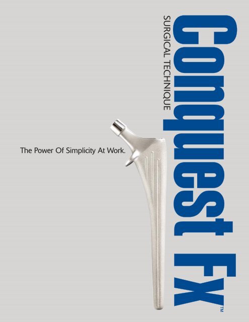
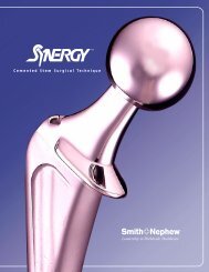
The Power Of Simplicity At Work.<br />
Conquest Fx<br />
SURGICAL TECHNIQUE
TAPERED<br />
HIP SYSTEM<br />
SURGICAL TECHNIQUE COMPLETED<br />
IN CONJUNCTION WITH<br />
Pe<strong>te</strong>r Brooks, M.D.<br />
Cleveland, Ohio<br />
Wayne M. Golds<strong>te</strong>in, M.D.<br />
Chicago, Illinois<br />
Gia<strong>nn</strong>i L. Maistrelli, M.D., F.R.C.S.(C)<br />
Toronto, Ontario, Canada<br />
Nota Bene: The <strong>te</strong>chnique description herein is made available to the healthcare professional to illustra<strong>te</strong> the authors’ su<strong>gg</strong>es<strong>te</strong>d<br />
treatment for the un<strong>com</strong>plica<strong>te</strong>d procedure. In the final analysis, the prefe<strong>rr</strong>ed treatment is that which addresses the n<strong>ee</strong>ds of the patient.
2<br />
INTRODUCTION
The Conquest FX s<strong>te</strong>m is part of the<br />
Synergy Tapered Hip Sys<strong>te</strong>m, which<br />
<strong>com</strong>prises a variety of cementless and<br />
cemen<strong>te</strong>d s<strong>te</strong>ms to address different<br />
patient n<strong>ee</strong>ds. These include a highperformance<br />
cemen<strong>te</strong>d s<strong>te</strong>m, a porous<br />
cementless s<strong>te</strong>m, and hydroxyapati<strong>te</strong>coa<strong>te</strong>d<br />
cementless s<strong>te</strong>ms, all of which<br />
can be implan<strong>te</strong>d using the same basic<br />
instruments.<br />
The Conquest FX s<strong>te</strong>m is a cobalt<br />
chrome s<strong>te</strong>m that m<strong>ee</strong>ts the n<strong>ee</strong>ds of<br />
those patients who will benefit from an<br />
economi<strong>cal</strong>, low-demand hip s<strong>te</strong>m that<br />
takes advantage of the Synergy instrumentation.<br />
It is designed to be used in<br />
fracture or arthritis cases and may be<br />
implan<strong>te</strong>d with or without cement. S<strong>te</strong>m<br />
sizing is 9 mm to 16 mm, in 1 mm<br />
increments. It is available in standard<br />
offset only and uses the entire line of<br />
Smith & Nephew heads available in a<br />
12/14 taper, including both bipolar<br />
and unipolar replacements.<br />
<br />
3
STEM SPECIFICATIONS<br />
SPECIFICATIONS<br />
Coni<strong>cal</strong><br />
Neck Cross S<strong>te</strong>m A-P M-L<br />
Size Angle Section Length Width Width<br />
9 131° 9 mm 125 mm 13 mm 28 mm<br />
10 131° 10 mm 130 mm 14 mm 29 mm<br />
11 131° 11 mm 135 mm 15 mm 30 mm<br />
12 131° 12 mm 140 mm 16 mm 31 mm<br />
13 131° 13 mm 145 mm 17 mm 32 mm<br />
14 131° 14 mm 150 mm 18 mm 33 mm<br />
15 131° 15 mm 150 mm 19 mm 34 mm<br />
16 131° 16 mm 150 mm 21 mm 35 mm<br />
NECK HEIGHT MM<br />
When Femoral Head Component Selec<strong>te</strong>d Is:<br />
Size –3 +0 +4 +8 +12 +16<br />
9 26 28 30 33 35 38<br />
10 26 28 31 33 36 39<br />
11 27 29 32 34 37 39<br />
12 28 30 32 35 37 40<br />
13 28 30 33 35 38 41<br />
14 29 31 33 36 39 41<br />
15 30 32 34 37 39 42<br />
16 30 32 35 37 40 43<br />
NECK OFFSET MM<br />
When Femoral Head Component Selec<strong>te</strong>d Is:<br />
Size –3 +0 +4 +8 +12 +16<br />
9 32 34 37 40 43 46<br />
10 33 35 38 41 44 47<br />
11 34 36 39 42 45 48<br />
12 34 37 40 43 46 49<br />
13 35 37 40 43 46 49<br />
14 36 38 41 44 47 50<br />
15 37 39 42 45 48 51<br />
16 37 40 43 46 49 52<br />
NECK NECK LENGTH LENGTH MM MM<br />
When Femoral Head Component Selec<strong>te</strong>d Is:<br />
Size –3 +0 +4 +8 +12 +16<br />
9 27 30 34 38 42 46<br />
10 28 30 34 38 42 46<br />
11 28 31 35 39 43 47<br />
12 29 32 36 40 44 48<br />
13 30 32 36 40 44 48<br />
14 30 33 37 41 45 49<br />
15 31 34 38 42 46 50<br />
16 31 34 38 42 46 50<br />
The Conquest FX s<strong>te</strong>m is for use with Smith & Nephew 12/14 taper femoral heads only.<br />
4
OFFSET<br />
M-L WIDTH<br />
+16*<br />
+12*<br />
+ 8<br />
+ 4<br />
+ 0<br />
–3<br />
-3 and +16 CoCr<br />
femoral heads available<br />
in 28 mm and 32 mm<br />
O.D. only.<br />
*Deno<strong>te</strong>s skir<strong>te</strong>d heads<br />
NOTE: For illustration purposes<br />
only. Surgi<strong>cal</strong> <strong>te</strong>mpla<strong>te</strong>s are available<br />
by contacting your Smith<br />
& Nephew Representative or<br />
Customer Service.<br />
NOT ACTUAL SIZE<br />
STEM<br />
LENGTH<br />
0<br />
10<br />
20<br />
30<br />
NECK<br />
LENGTH<br />
CONICAL<br />
CROSS<br />
SECTION<br />
NECK HEIGHT<br />
A-P WIDTH<br />
<br />
5
PREOPERATIVE PLANNING<br />
Leg length de<strong>te</strong>rmination is difficult in fracture<br />
cases, particularly with a displaced fracture. The<br />
lack of skeletal continuity of<strong>te</strong>n prevents accura<strong>te</strong><br />
measurement. Other factors that can be assessed<br />
during surgery, such as joint stability and soft<br />
tissue <strong>te</strong>nsion, are re<strong>com</strong>mended. Each of these<br />
assessments helps in selecting the appropria<strong>te</strong><br />
trials during surgery.<br />
In elective procedures, leg length should be de<strong>te</strong>rmined<br />
before surgery. A tape measure may be used<br />
from the an<strong>te</strong>rior superior iliac spine to the medial<br />
malleolus to assess true leg length. Both of these<br />
landmarks offer a reliable bony prominence when<br />
approached from below. Al<strong>te</strong>rnatively, the A-P<br />
radiograph of the pelvis may be used to evalua<strong>te</strong> leg<br />
lengths. A straight edge is held tangential to the two<br />
obturator foramen or the ischial tuberosities, and<br />
the resulting line is marked where it in<strong>te</strong>rsects the<br />
femurs medially. Comparing where this line m<strong>ee</strong>ts<br />
the two femurs gives a measurement of leg length<br />
discrepancy, taking X-ray magnification into<br />
account (Figure 1).<br />
Conquest FX <strong>te</strong>mpla<strong>te</strong>s are used to select a s<strong>te</strong>m size<br />
and to predict the n<strong>ee</strong>ded head replacement for the<br />
required leg length. First, the acetabular <strong>com</strong>ponent,<br />
whether a fixed socket, bipolar or unipolar, is <strong>te</strong>mpla<strong>te</strong>d<br />
and the cen<strong>te</strong>r of rotation marked through<br />
the hole provided. The s<strong>te</strong>m <strong>te</strong>mpla<strong>te</strong> is chosen by<br />
overlaying successive sizes until a co<strong>rr</strong>ect size is<br />
found (Figure 2).<br />
The co<strong>rr</strong>ect size is one where the shoulder of the s<strong>te</strong>m<br />
is level with the junction of the grea<strong>te</strong>r trochan<strong>te</strong>r<br />
and the femoral neck, the s<strong>te</strong>m (or indica<strong>te</strong>d<br />
cement mantle, if desired) is snug in the shaft<br />
and there is good proximal fill. This usually results<br />
in a <strong>cal</strong>car os<strong>te</strong>otomy approxima<strong>te</strong>ly 1.5 cm or one<br />
finger breadth above the lesser trochan<strong>te</strong>r. Normal<br />
patient anatomy varies widely. Neck shaft angles<br />
and femoral neck lengths should be considered<br />
before the femoral head is resec<strong>te</strong>d.<br />
15<br />
+16<br />
+12<br />
+ 8<br />
+ 4<br />
+ 0<br />
–3<br />
*<br />
*<br />
For use with Smith &<br />
Nephew 12/14 femoral<br />
heads only.<br />
-3 and +16 CoCr<br />
femoral heads available<br />
in 28 mm and 32 mm<br />
O.D. only.<br />
*Deno<strong>te</strong>s skir<strong>te</strong>d heads<br />
150 mm<br />
39 mm<br />
0<br />
10<br />
20<br />
30<br />
C O N Q U E S T Fx S I Z E 1 5<br />
34 mm<br />
SIZE<br />
15<br />
120% MAGNIFNICATION<br />
32 mm<br />
0<br />
10<br />
20<br />
30<br />
40<br />
50<br />
60<br />
70<br />
80<br />
90<br />
100<br />
110<br />
120<br />
130<br />
140<br />
150<br />
MM<br />
160<br />
170<br />
180<br />
190<br />
200<br />
Re<strong>com</strong>mended<br />
Centralizer 13 mm<br />
210<br />
220<br />
Size 17 Broach Profile<br />
230<br />
©1999 Smith & Nephew, Inc., Memphis, TN U.S.A.<br />
Conquest Fx is a trademark of Smith & Nephew, Inc.<br />
Figure 2. An<strong>te</strong>ropos<strong>te</strong>rior radiograph<br />
demonstrating proper <strong>te</strong>mplating method.<br />
Figure 1. An<strong>te</strong>ropos<strong>te</strong>rior radiograph demonstrating one method<br />
of de<strong>te</strong>rmining leg length inequality.<br />
6
It is important to check that the s<strong>te</strong>m fits properly<br />
into the femur on the la<strong>te</strong>ral radiograph. It is<br />
the la<strong>te</strong>ral radiograph that shows best where<br />
thr<strong>ee</strong>-point fixation occurs.<br />
Once the appropria<strong>te</strong> s<strong>te</strong>m <strong>te</strong>mpla<strong>te</strong> is held at the<br />
co<strong>rr</strong>ect level, the range of neck lengths is assessed.<br />
The hole for any given neck length marks the cen<strong>te</strong>r<br />
of rotation for that head, and <strong>com</strong>paring this to the<br />
acetabular cen<strong>te</strong>r of rotation gives the change in<br />
offset and leg length that will be achieved af<strong>te</strong>r<br />
reduction. However, <strong>te</strong>mplating does not elimina<strong>te</strong><br />
the n<strong>ee</strong>d for careful trial reduction using first the<br />
broach and la<strong>te</strong>r, the implan<strong>te</strong>d s<strong>te</strong>m.<br />
A properly implan<strong>te</strong>d Conquest Fx s<strong>te</strong>m that provides<br />
both normal leg length and offset are shown in<br />
Figure 3. For this patient, the femoral implant<br />
was cemen<strong>te</strong>d in place.<br />
Figure 3. An<strong>te</strong>ropos<strong>te</strong>rior radiograph of<br />
a properly implan<strong>te</strong>d Conquest FX s<strong>te</strong>m<br />
used in cemen<strong>te</strong>d mode.<br />
<br />
7
1. Expose the Hip<br />
Position the patient and expose the hip joint in<br />
the desired ma<strong>nn</strong>er. Prior to dislocation, place<br />
a pin for measuring leg length in either the iliac<br />
crest or supra-acetabular bone. Make a small mark<br />
using cau<strong>te</strong>ry or ink on a convenient place on the<br />
femur, such as the vastus ridge. Measure and<br />
record the distance betw<strong>ee</strong>n these two points with<br />
a ruler or other device designed for this purpose.<br />
2. Femoral Os<strong>te</strong>otomy<br />
The level of the femoral neck<br />
os<strong>te</strong>otomy will have b<strong>ee</strong>n<br />
selec<strong>te</strong>d during preoperative<br />
<strong>te</strong>mplating. The angle of this<br />
os<strong>te</strong>otomy is de<strong>te</strong>rmined using the<br />
os<strong>te</strong>otomy guide, held parallel to the shaft<br />
of the femur. A line may be marked using<br />
the cau<strong>te</strong>ry tip.<br />
If the femoral shaft is held parallel to the<br />
floor and the femur is in<strong>te</strong>rnally rota<strong>te</strong>d<br />
an amount equal to the desired <strong>com</strong>ponent<br />
an<strong>te</strong>version, the saw may be<br />
poin<strong>te</strong>d straight down to achieve<br />
a properly an<strong>te</strong>ver<strong>te</strong>d cut without<br />
unwan<strong>te</strong>d flexion or ex<strong>te</strong>nsion<br />
(Figure 1).<br />
Figure 1<br />
8
3. Prepare<br />
Acetabulum<br />
If acetabular reconstruction is<br />
required, prepare the acetabulum<br />
according to the re<strong>com</strong>mended<br />
<strong>te</strong>chnique for the chosen implant.<br />
4. Femoral Canal<br />
Preparation<br />
The box os<strong>te</strong>otome is used<br />
first to remove remnants<br />
of the la<strong>te</strong>ral femoral<br />
neck (Figure 2). Using<br />
the T-handle, sound the<br />
canal with the tapered<br />
canal finder (Figure 3).<br />
NOTE: It is important to<br />
start la<strong>te</strong>rally to avoid varus<br />
positioning of the implants.<br />
Figure 2<br />
Figure 3<br />
<br />
9
5. Femoral Reaming<br />
Femoral reaming may be done using<br />
the T-handle or with power. Start<br />
la<strong>te</strong>rally to maintain alignment with<br />
the femoral shaft. Each reamer is<br />
marked with two or thr<strong>ee</strong> lines. Stop<br />
reaming when the line associa<strong>te</strong>d with<br />
the implant size that was <strong>te</strong>mpla<strong>te</strong>d<br />
reaches the medial <strong>cal</strong>car (Figure 4).<br />
NOTE: It is important to stay la<strong>te</strong>ral with the<br />
femoral reamers to help insure alignment<br />
with the femoral axis.<br />
Figure 4<br />
10
6. Broach Assembly/<br />
Disassembly<br />
Assemble the broach to the broach<br />
handle by placing the broach post<br />
in the clamp. Use thumb to lock the<br />
clamp onto the broach. A modular<br />
an<strong>te</strong>version handle can be assembled<br />
to the broach handle to provide<br />
version control (Figure 5).<br />
Disassemble the broach from the broach<br />
handle by placing two fingers (index<br />
and middle) into the rectangular slot.<br />
Apply pressure to the release bar by<br />
squ<strong>ee</strong>zing two fingers toward the<br />
thumb resting on the medial side of<br />
the broach handle frame (Figure 6).<br />
Figure 5<br />
Figure 6<br />
<br />
11
7. Femoral Broaching<br />
Begin with a broach that is at least<br />
two sizes smaller than the in<strong>te</strong>nded<br />
implant. K<strong>ee</strong>ping the desired an<strong>te</strong>version,<br />
broach progressively until the<br />
desired fit is achieved. Stop broaching<br />
when the top of the <strong>te</strong>mpla<strong>te</strong>d size<br />
broach coincides with the neck resection.<br />
It is important to start in the<br />
co<strong>rr</strong>ect la<strong>te</strong>ral position to maintain<br />
alignment with the shaft (Figure 7).<br />
Figure 7<br />
NOTE: For those surgeons who prefer<br />
a broach-only <strong>te</strong>chnique, full-cutting<br />
broaches are available.<br />
12
8. Calcar<br />
Preparation<br />
With the final broach fully<br />
sea<strong>te</strong>d, remove the broach<br />
handle and ream the <strong>cal</strong>car<br />
with either the small or large<br />
<strong>cal</strong>car reamer (Figure 8).<br />
Figure 8<br />
9. Trial Reduction<br />
Place the trial neck that<br />
matches the broach size onto<br />
the broach post. If a high offset<br />
is n<strong>ee</strong>ded, either the Synergy<br />
Porous, Synergy HA or Synergy<br />
Cemen<strong>te</strong>d s<strong>te</strong>m must be used.<br />
NOTE: Only standard offset<br />
is available in the Conquest FX.<br />
Do not use the high offset (HO)<br />
neck trial for trialing the<br />
Conquest FX s<strong>te</strong>m.<br />
Place the chosen head trial<br />
onto the neck trial (Figure 9).<br />
Reduce the hip and evalua<strong>te</strong><br />
in the following ways:<br />
Figure 9<br />
<br />
13
9. Trial Reduction (cont.)<br />
1. Soft tissue <strong>te</strong>nsion – some shuck is<br />
normal when applying a longitudinal<br />
distraction force to the hip. Shuck<br />
should not be excessive, and the hip<br />
should not disloca<strong>te</strong> (Figure 10).<br />
2. An<strong>te</strong>rior stability – place the leg<br />
in full adduction, full ex<strong>te</strong>nsion<br />
and hyperex<strong>te</strong>nsion, while exerting<br />
an ex<strong>te</strong>rnal rotation force. If the hip<br />
ca<strong>nn</strong>ot be fully ex<strong>te</strong>nded, it may<br />
be too tight. If it disloca<strong>te</strong>s easily,<br />
it is too loose and impingement<br />
must be addressed or <strong>com</strong>ponent<br />
malposition exists (Figure 11).<br />
3. Pos<strong>te</strong>rior stability – place the leg<br />
in neutral adduction and 90° flexion.<br />
Gradually rota<strong>te</strong> in<strong>te</strong>rnally. If it disloca<strong>te</strong>s<br />
with minimal in<strong>te</strong>rnal rotation,<br />
it is too loose and impingement must<br />
be addressed or <strong>com</strong>ponent malposition<br />
exists (Figure 12).<br />
Figure 10<br />
Figure 11<br />
Figure 12<br />
14
9. Trial Reduction (cont.)<br />
4. Sl<strong>ee</strong>p position – place the leg in the<br />
“sl<strong>ee</strong>p position” with the opera<strong>te</strong>d leg<br />
semiflexed, adduc<strong>te</strong>d and in<strong>te</strong>rnally<br />
rota<strong>te</strong>d over the other leg. Apply axial<br />
force to try to disloca<strong>te</strong>. This position<br />
represents a dangerous unstable position<br />
that may be adop<strong>te</strong>d by a patient<br />
sl<strong>ee</strong>ping on their nonopera<strong>te</strong>d side<br />
(Figure 13).<br />
5. Measure leg length – using the pin<br />
placed earlier in the iliac crest or<br />
supra-acetabular bone, remeasure the<br />
distance to the mark on the proximal<br />
femur. This indica<strong>te</strong>s the change in<br />
leg length with the selec<strong>te</strong>d neck trial.<br />
This is the last <strong>te</strong>st of the trial. Stability<br />
is <strong>te</strong>s<strong>te</strong>d first, because it is more important<br />
than leg length, which can be<br />
adjus<strong>te</strong>d by means of a shoe lift,<br />
if necessary, while postoperative<br />
instability of<strong>te</strong>n requires more<br />
invasive treatment.<br />
Figure 13<br />
<br />
15
10. S<strong>te</strong>m Insertion<br />
The Conquest FX s<strong>te</strong>m is designed<br />
so that it may be inser<strong>te</strong>d without<br />
cement. If this is desired, use the<br />
two-piece threaded driver to impact<br />
the chosen s<strong>te</strong>m into the prepared<br />
femur, using gentle mallet blows<br />
until fully sea<strong>te</strong>d. Ensure that it is<br />
stable. A line-to-line fit is achieved<br />
betw<strong>ee</strong>n the implant and bone when<br />
the implant that is chosen matches<br />
the last reamer and broach that<br />
are used (Figure 14).<br />
If cemen<strong>te</strong>d fixation is prefe<strong>rr</strong>ed,<br />
prepare the femoral canal by plu<strong>gg</strong>ing,<br />
brushing, cleaning with pulsatile<br />
lavage and drying with gauze sponges.<br />
Introduce the cement in its doughy<br />
phase using a cement gun in retrograde<br />
fashion, and pressurize the<br />
cement with a cement pressurizer.<br />
Selecting an implant two sizes smaller<br />
than the last broach will result in a<br />
minimum cement mantle of 1 mm<br />
all around, but with pressurization,<br />
much grea<strong>te</strong>r cement mantles are<br />
s<strong>ee</strong>n in practice. A cement centralizer<br />
of the appropria<strong>te</strong> size may be placed<br />
in the hole at the end of the s<strong>te</strong>m.<br />
The non-threaded driver is prefe<strong>rr</strong>ed<br />
for cemen<strong>te</strong>d fixation so that small<br />
hand movements are not transmit<strong>te</strong>d<br />
to the s<strong>te</strong>m during cement curing<br />
(Figure 15).<br />
NOTE: Regardless of the method of<br />
s<strong>te</strong>m fixation, a trial reduction should<br />
be performed with the implants.<br />
Cemen<strong>te</strong>d<br />
S<strong>te</strong>m Inser<strong>te</strong>r<br />
Figure 14<br />
Cementless<br />
S<strong>te</strong>m Inser<strong>te</strong>r<br />
Figure 15<br />
16
11. Final Trial<br />
Reduction<br />
A final trial reduction may<br />
be performed at this time<br />
using trial femoral heads<br />
(Figure 16).<br />
Figure 16<br />
12. Femoral Head<br />
Assembly<br />
Clean and dry the taper of the<br />
femoral <strong>com</strong>ponent. Impact the<br />
chosen head <strong>com</strong>ponent onto the<br />
femoral <strong>com</strong>ponent using a mallet<br />
and the femoral head impactor.<br />
Strike the femoral head impactor<br />
firmly with a mallet several times.<br />
The femoral head impactor should<br />
be held in line with the neck of<br />
the hip s<strong>te</strong>m (Figure 17).<br />
Expose and i<strong>rr</strong>iga<strong>te</strong> the<br />
acetabulum to ensure that<br />
no debris will be in<strong>te</strong>rposed<br />
in the joint. Carefully reduce<br />
the hip. Do a final check<br />
of soft tissue <strong>te</strong>nsion and<br />
leg length. Remove the<br />
leg length pin. Close<br />
in standard fashion.<br />
Figure 17<br />
<br />
17
CONQUEST FX FEMORAL STEM & HEAD COMPONENTS<br />
Porous-Coa<strong>te</strong>d Synergy S<strong>te</strong>ms<br />
Titanium 6Al-4V<br />
Standard High Offset<br />
Size Length Cat. No. Cat. No.<br />
9 135 mm 7130-6609 7130-6109<br />
10 140 mm 7130-6610 7130-6110<br />
11 145 mm 7130-6611 7130-6111<br />
12 150 mm 7130-6612 7130-6112<br />
13 155 mm 7130-6613 7130-6113<br />
14 160 mm 7130-6614 7130-6114<br />
15 165 mm 7130-6615 7130-6115<br />
16 170 mm 7130-6616 7130-6116<br />
17 175 mm 7130-6617 7130-6117<br />
18 180 mm 7130-6618 7130-6118<br />
Conquest Fx S<strong>te</strong>ms<br />
CoCr<br />
Size Length Cat. No.<br />
9 125 mm 7131-6509<br />
10 130 mm 7131-6510<br />
11 135 mm 7131-6511<br />
12 140 mm 7131-6512<br />
13 145 mm 7131-6513<br />
14 150 mm 7131-6514<br />
15 150 mm 7131-6515<br />
16 150 mm 7131-6516<br />
HA-Coa<strong>te</strong>d Synergy S<strong>te</strong>ms<br />
Titanium 6Al-4V<br />
Standard High Offset<br />
Size Length Cat. No. Cat. No.<br />
9 135 mm 7130-6709 7130-6409<br />
10 140 mm 7130-6710 7130-6410<br />
11 145 mm 7130-6711 7130-6411<br />
12 150 mm 7130-6712 7130-6412<br />
13 155 mm 7130-6713 7130-6413<br />
14 160 mm 7130-6714 7130-6414<br />
15 165 mm 7130-6715 7130-6415<br />
16 170 mm 7130-6716 7130-6416<br />
17 175 mm 7130-6717 7130-6417<br />
18 180 mm 7130-6718 7130-6418<br />
C A T A L O G I N F O R M A T I O N<br />
Titanium Press-Fit Synergy S<strong>te</strong>ms<br />
Titanium 6Al-4V<br />
Size Length Cat. No.<br />
9 135 mm 7130-6809<br />
10 140 mm 7130-6810<br />
11 145 mm 7130-6811<br />
12 150 mm 7130-6812<br />
13 155 mm 7130-6813<br />
14 160 mm 7130-6814<br />
15 165 mm 7130-6815<br />
16 170 mm 7130-6816<br />
17 175 mm 7130-6817<br />
18 180 mm 7130-6818<br />
Cemen<strong>te</strong>d Synergy S<strong>te</strong>ms<br />
Forged CoCr<br />
Standard High Offset<br />
Size Length Cat. No. Cat. No.<br />
9 110 mm 7131-6009 7131-6209<br />
10 115 mm 7131-6010 7131-6210<br />
11 120 mm 7131-6011 7131-6211<br />
12 125 mm 7131-6012 7131-6212<br />
13 130 mm 7131-6013 7131-6213<br />
14 135 mm 7131-6014 7131-6214<br />
15 140 mm 7131-6015 7131-6215<br />
19
CONQUEST FX FEMORAL STEM & HEAD COMPONENTS<br />
Zirconia 12/14 Taper<br />
Femoral Heads<br />
Neck<br />
Length 22 mm 26 mm 28 mm<br />
+0 — 7132-0026 7132-0028<br />
+4 7132-0422 7132-0426 7132-0428<br />
+8 7132-0822 7132-0826 7132-0828<br />
CoCr 12/14 Femoral Heads<br />
Cobalt Chromium – ASTM F 799<br />
Neck<br />
Length 22 mm 26 mm 28 mm 32 mm<br />
–3 — — 7130-2803 7130-3203<br />
+0 7130-2200 7130-2600 7130-2800 7130-3200<br />
+4 7130-2204 7130-2604 7130-2804 7130-3204<br />
+8 7130-2208 7130-2608 7130-2808 7130-3208<br />
+12 7130-2212 7130-2612 7130-2812 7130-3212<br />
+16 — — 7130-2816 7130-3216<br />
Invis Distal Centralizers<br />
Cat. No. O.D. Cat. No. O.D.<br />
7131-3208 8 mm 7131-3215 15 mm<br />
7131-3209 9 mm 7131-3216 16 mm<br />
7131-3210 10 mm 7131-3217 17 mm<br />
7131-3211 11 mm 7131-3218 18 mm<br />
7131-3212 12 mm 7131-3219 19 mm<br />
7131-3213 13 mm 7131-3220 20 mm<br />
7131-3214 14 mm 7131-3221 21 mm<br />
20
CONQUEST FX<br />
Femoral Instrumentation Tray No. 1<br />
Cat. No. 7136-6201<br />
Os<strong>te</strong>otomy Guide<br />
Cat. No. 7136-4000<br />
Box Os<strong>te</strong>otome<br />
Cat. No. Size<br />
7136-4002 Small<br />
7136-4003 Large<br />
Canal Finder<br />
Cat. No. 7136-4001<br />
INSTRUMENTATION<br />
Tapered Reamer<br />
Cat. No. Size<br />
7136-6209 8-9-10<br />
7136-6211 11-12<br />
7136-6213 13-14<br />
7136-6215 15-16<br />
7136-6217 17-18<br />
Broach Handle<br />
(Two Per Set)<br />
Cat. No. 7136-4007<br />
C A T A L O G I N F O R M A T I O N<br />
T-Handle<br />
Cat. No. 7136-4006<br />
An<strong>te</strong>version Handle<br />
Cat. No. 7136-4012<br />
21
CONQUEST FX<br />
INSTRUMENTATION<br />
Femoral Instrumentation Tray No. 2<br />
Cat. No. 7136-6202<br />
Tapered Broach<br />
Cat. No. Size Cat. No. Size<br />
7136-6308 8 7136-6314 14<br />
7136-6309 9 7136-6315 15<br />
7136-6310 10 7136-6316 16<br />
7136-6311 11 7136-6317 17<br />
7136-6312 12 7136-6318 18<br />
7136-6313 13<br />
Trial Neck, Standard<br />
Cat. No. Size<br />
7136-6408 8-13<br />
7136-6414 14-18<br />
Trial Neck, High Offset<br />
Cat. No. Size<br />
7136-6508 8-13<br />
7136-6514 14-18<br />
Fully Toothed Broach<br />
Cat. No. Size Cat. No. Size<br />
7136-6708 8 7136-6714 14<br />
7136-6709 9 7136-6715 15<br />
7136-6710 10 7136-6716 16<br />
7136-6711 11 7136-6717 17<br />
7136-6712 12 7136-6718 18<br />
7136-6713 13<br />
Calcar Reamer<br />
Cat. No. Size<br />
7136-4004 Small<br />
7136-4005 Large<br />
22
S<strong>te</strong>m Inser<strong>te</strong>r<br />
Frame<br />
Cat. No. 7136-4008<br />
Cemen<strong>te</strong>d S<strong>te</strong>m<br />
Inser<strong>te</strong>r<br />
Cat. No. 7136-4014<br />
CONQUEST FX<br />
INSTRUMENTATION<br />
Trial 12/14 Taper Femoral Heads<br />
Neck Color 22 mm 26 mm 32 mm<br />
Length Code Optional Optional 28 mm Optional<br />
–3 Gr<strong>ee</strong>n — — 7135-2803 7135-3203<br />
+0 Yellow 7135-2200 7135-2600 7135-2800 7135-3200<br />
+4 Red 7135-2204 7135-2604 7135-2804 7135-3204<br />
+8 Whi<strong>te</strong> 7135-2208 7135-2608 7135-2808 7135-3208<br />
+12 Blue 7135-2212 7135-2612 7135-2812 7135-3212<br />
+16 Black — — 7135-2816 7135-3216<br />
Femoral Head<br />
Impactor<br />
Cat. No. 7136-4009<br />
Slap Hammer Weight<br />
Cat. No. 7136-4010<br />
C A T A L O G I N F O R M A T I O N<br />
S<strong>te</strong>m Inser<strong>te</strong>r<br />
Pommel<br />
Cat. No. 7136-4011<br />
23
IMPORTANT NOTE<br />
Total hip replacement arthroplasty has be<strong>com</strong>e a successful procedure<br />
for relieving pain and restoring motion in patients who are disabled<br />
from hip arthropathy. The goals of total hip replacement are to<br />
decrease pain, increase function, and increase mobility.<br />
MATERIALS<br />
The Total Hip Sys<strong>te</strong>m is manufactured from ma<strong>te</strong>rials as outlined<br />
below. The <strong>com</strong>ponent ma<strong>te</strong>rial is provided on the outside carton label.<br />
Component Ma<strong>te</strong>rial Ma<strong>te</strong>rial Standards<br />
Femoral Components Ti-6Al-4V ASTM F 136 and ISO 5832/3 or<br />
or ASTM F 1472 and ISO 5832/3<br />
Co-Cr-Mo or<br />
ASTM F 799 and ISO 5832/12<br />
or<br />
ASTM F 75 and ISO 5832/4<br />
Acetabular shells Ti-6Al-4V ASTM F 1472 and ISO 5832/3<br />
Proximal pads<br />
Taper sl<strong>ee</strong>ves<br />
Distal sl<strong>ee</strong>ves<br />
Fixation screws and pegs<br />
Hole covers<br />
Acetabular <strong>com</strong>ponents UHMWPE ASTM F 648<br />
Acetabular liners<br />
Femoral centralizers PMMA Not applicable<br />
Acetabular spacer pods<br />
X-ray marking wire Co-Cr-Mo ASTM F 90 and ISO 5832/5<br />
Acetabular Reconstruction CP Titanium ASTM F 67 and ISO 5832/2<br />
Ring<br />
Acetabular<br />
Reinforcement Ring<br />
Femoral Heads Co-Cr-Mo ASTM F 799 and ISO 5832/12<br />
Zirconia ISO 13356<br />
Ceramic<br />
Porous titanium <strong>com</strong>ponents and porous Co-Cr-Mo <strong>com</strong>ponents are<br />
coa<strong>te</strong>d with <strong>com</strong>mercially pure (C.P.) titanium beads (ASTM F 67 and<br />
ISO 5832/2) and Co-Cr-Mo beads (ASTM F 75), respectively.<br />
Hydroxylapati<strong>te</strong> coatings include HA (ASTM F 1185) that is applied<br />
either on a grit blas<strong>te</strong>d or porous surface. NOTE: HA coa<strong>te</strong>d porous<br />
implants are not available in the USA.<br />
Zirconia ceramic femoral heads are yttria stabilized zirconia ceramic.<br />
Some of the alloys n<strong>ee</strong>ded to produce orthopedic implants contain<br />
some metallic <strong>com</strong>ponents that may be carcinogenic in tissue cultures<br />
or intact organism under very unique circumstances. Questions have<br />
b<strong>ee</strong>n raised in the scientific li<strong>te</strong>rature as to whether or not these alloys<br />
may be carcinogenic in implant recipients. Studies conduc<strong>te</strong>d to evalua<strong>te</strong><br />
this issue have not identified conclusive evidence of such phenomenon,<br />
in spi<strong>te</strong> of the millions of implants in use.<br />
DESCRIPTION OF SYSTEM<br />
The Total Hip Sys<strong>te</strong>m consists of femoral <strong>com</strong>ponents, proximal<br />
pads, taper sl<strong>ee</strong>ves, distal sl<strong>ee</strong>ves, acetabular <strong>com</strong>ponents, fixation<br />
screws and pegs, hole covers, centralizers, and femoral heads.<br />
Components may be grit blas<strong>te</strong>d, porous coa<strong>te</strong>d, hydroxylapati<strong>te</strong><br />
(HA) coa<strong>te</strong>d, or HA porous coa<strong>te</strong>d. All implantable devices are<br />
designed for single use only.<br />
Femoral Components<br />
Femoral <strong>com</strong>ponents are available in a variety of sizes. Porous coa<strong>te</strong>d<br />
<strong>com</strong>ponents are coa<strong>te</strong>d for biologi<strong>cal</strong> ingrowth. Proximally and distally<br />
modular femoral <strong>com</strong>ponents accept proximal pads and distal sl<strong>ee</strong>ves,<br />
respectively. Non-porous femoral <strong>com</strong>ponents can feature PMMA centralizers<br />
that help produce a uniform thickness of cement in a concentric<br />
ma<strong>nn</strong>er.<br />
Femoral <strong>com</strong>ponents are available with a small, large (14/16), or<br />
12/14 global taper (gage diame<strong>te</strong>rs 0.404, 0.564, and 0.500 inches,<br />
respectively).<br />
Small taper femoral <strong>com</strong>ponents ma<strong>te</strong> and lock directly with a 22 mm<br />
metal or ceramic head. The small taper also ma<strong>te</strong>s with a taper<br />
sl<strong>ee</strong>ve which, in turn, ma<strong>te</strong>s with either metal or ceramic heads (26,<br />
28, or 32 mm), bipolar or unipolar <strong>com</strong>ponents.<br />
Large taper femoral <strong>com</strong>ponents ma<strong>te</strong> and lock with either metal heads<br />
(26, 28, or 32 mm), ceramic heads (22, 28 or 32 mm), bipolar or unipolar<br />
<strong>com</strong>ponents.<br />
Femoral <strong>com</strong>ponents with a 12/14 taper ma<strong>te</strong> and lock with either<br />
metal heads (22, 26, 28, or 32 mm), ceramic heads (26 or 28 mm),<br />
bipolar or unipolar <strong>com</strong>ponents.<br />
Small, large, and 12/14 taper femoral <strong>com</strong>ponent tapers are<br />
machined to ma<strong>te</strong> and lock with ceramic heads, thus preventing rotation<br />
of the ceramic head on the s<strong>te</strong>m, the lat<strong>te</strong>r would cause wear of<br />
the s<strong>te</strong>m taper.<br />
IMPORTANT MEDICAL INFORMATION<br />
Warnings and Precautions<br />
Total Hip Sys<strong>te</strong>m<br />
Taper Sl<strong>ee</strong>ves<br />
A taper sl<strong>ee</strong>ve is required to be impac<strong>te</strong>d on the small taper femoral<br />
<strong>com</strong>ponent prior to impacting a femoral head size 26, 28, or 32 mm. A<br />
taper sl<strong>ee</strong>ve is required to attach a unipolar head. Unipolar taper<br />
sl<strong>ee</strong>ves are available in small, large, and 12/14 tapers. Never place<br />
more than one taper sl<strong>ee</strong>ve on a femoral <strong>com</strong>ponent.<br />
Femoral Heads<br />
Cobalt chromium (22, 26, 28, and 32 mm) and ceramic (22, 26, 28, and<br />
32 mm) heads are available in multiple neck lengths for proper<br />
anatomic and musculature fit. Heads are highly polished for reduced<br />
friction and wear. The following zirconia ceramic heads are available<br />
for use only with small (0.404) and large (.564) taper femoral <strong>com</strong>ponents.<br />
Zirconia<br />
Head<br />
Ceramic Diame<strong>te</strong>r Neck Length<br />
42-7815 32 mm Standard 0 mm<br />
42-7816 32 mm Long 4 mm<br />
42-7817 32 mm X-Long 8 mm<br />
42-7818 28 mm Standard 0 mm<br />
42-7819 28 mm Long 4 mm<br />
42-7820 28 mm X-Long 8 mm<br />
No<strong>te</strong>: 32 mm heads with a -3 mm neck length are not available for use<br />
with the small taper s<strong>te</strong>ms.<br />
In addition to the <strong>com</strong>ponents lis<strong>te</strong>d above, the following <strong>com</strong>ponents<br />
are available for use only with small (0.404) taper femoral <strong>com</strong>ponents<br />
Zirconia<br />
Head<br />
Ceramic Diame<strong>te</strong>r Neck Length<br />
7132-0002 22 mm Long 4 mm<br />
7132-0006 22 mm X-Long 8 mm<br />
No<strong>te</strong>: 22 mm Zirconia Ceramic Heads used with small (0.404) taper<br />
femoral <strong>com</strong>ponents are not available in the USA.<br />
The following zirconia ceramic heads are available for use only with<br />
12/14 taper femoral <strong>com</strong>ponents:<br />
Zirconia<br />
Head<br />
Ceramic Diame<strong>te</strong>r Neck Length<br />
7132-0028 28 mm Standard 0 mm<br />
7132-0428 28 mm Long 4 mm<br />
7132-0828 28 mm X-Long 8 mm<br />
7132-0026 26 mm Standard 0 mm<br />
7132-0426 26 mm Long 4 mm<br />
7132-0826 26 mm X-Long 8 mm<br />
7132-0422 22 mm Long 4 mm<br />
7132-0822 22 mm X-Long 8 mm<br />
Acetabular Components<br />
Acetabular <strong>com</strong>ponents can be one piece all polyethylene or twopiece<br />
<strong>com</strong>ponents consisting of a titanium shell and a polyethylene<br />
liner. Please s<strong>ee</strong> Warnings and Precautions for specific information<br />
on screws, pegs and hole covers use. Acetabular reinforcement and<br />
reconstruction rings are used with an all polyethylene acetabular<br />
<strong>com</strong>ponent.<br />
Femoral <strong>com</strong>ponents and femoral heads are designed for use with any<br />
Smith & Nephew polyethylene acetabular <strong>com</strong>ponent or polyethylenelined,<br />
metal-backed acetabular <strong>com</strong>ponent having an appropria<strong>te</strong>lysized<br />
inside diame<strong>te</strong>r.<br />
INDICATIONS, CONTRAINDICATIONS, AND ADVERSE EFFECTS<br />
Hip <strong>com</strong>ponents are indica<strong>te</strong>d for individuals undergoing primary and<br />
revision surgery where other treatments or devices have failed in rehabilitating<br />
hips damaged as a result of trauma or noninflammatory<br />
degenerative joint disease (NIDJD) or any of its <strong>com</strong>posi<strong>te</strong> diagnoses<br />
of os<strong>te</strong>oarthritis, avascular necrosis, traumatic arthritis, slipped capital<br />
epiphysis, fused hip, fracture of the pelvis, and diastrophic variant.<br />
Hip <strong>com</strong>ponents are also indica<strong>te</strong>d for inflammatory degenerative joint<br />
disease including rheumatoid arthritis, arthritis secondary to a variety<br />
of diseases and anomalies, and congenital dysplasia; old, remo<strong>te</strong><br />
os<strong>te</strong>omyelitis with an ex<strong>te</strong>nded drainage-fr<strong>ee</strong> period, in which case, the<br />
patient should be warned of an above normal danger of infection postoperatively;<br />
treatments of nonunion, femoral neck fracture and<br />
trochan<strong>te</strong>ric fractures of the proximal femur with heads involvement<br />
that are unmanageable using other <strong>te</strong>chniques; endoprosthesis,<br />
femoral os<strong>te</strong>otomy, or Girdlestone resection; fracture-dislocation of the<br />
hip; and co<strong>rr</strong>ection of deformity.<br />
Acetabular reinforcement and reconstruction rings are in<strong>te</strong>nded to be<br />
used in primary and revision surgeries where the acetabulum has the<br />
deficiencies of the acetabular roof, an<strong>te</strong>rior or pos<strong>te</strong>rior pillar, medial<br />
wall deficiency, and / or protrusion as a result of the indications lis<strong>te</strong>d<br />
previously.<br />
Some of the diagnoses lis<strong>te</strong>d above and below may also increase the<br />
chance of <strong>com</strong>plications and reduce the chance of a satisfactory result.<br />
Contraindications<br />
1. Conditions that would elimina<strong>te</strong> or <strong>te</strong>nd to elimina<strong>te</strong> adequa<strong>te</strong><br />
implant support or prevent the use of an appropria<strong>te</strong>ly-sized<br />
implant, e.g.:<br />
a. blood supply limitations;<br />
b. insufficient quantity or quality of bone support, e.g., os<strong>te</strong>oporosis,<br />
or metabolic disorders which may impair bone formation,<br />
and os<strong>te</strong>omalacia; and<br />
c. infections or other conditions which lead to increased bone<br />
resorption.<br />
2. Mental or neurologi<strong>cal</strong> conditions which <strong>te</strong>nd to impair the patient's<br />
ability or willingness to restrict activities.<br />
3. Physi<strong>cal</strong> conditions or activities which <strong>te</strong>nd to place extreme loads<br />
on implants, e.g., Charcot joints, muscle deficiencies, multiple joint<br />
disabilities, etc.<br />
4. Skeletal immaturity.<br />
5. The zirconia ceramic head is contraindica<strong>te</strong>d for use with any other<br />
product than an UHMW polyethylene cup or a metal backed<br />
UHMW polyethylene cup.<br />
Contraindications may be relative or absolu<strong>te</strong> and must be carefully<br />
weigh<strong>te</strong>d against the patient's entire evaluation and the prognosis for<br />
possible al<strong>te</strong>rnative procedures such as non-operative treatment,<br />
arthrodesis, femoral os<strong>te</strong>otomy, pelvic os<strong>te</strong>otomy, resection arthroplasty,<br />
hemiarthroplasty and others.<br />
Conditions presenting increased risk of failure include: os<strong>te</strong>oporosis,<br />
metabolic disorders which may impair bone formation, and<br />
os<strong>te</strong>omalacia.<br />
Possible Adverse Effects<br />
1. Wear of the polyethylene articulating surfaces of acetabular <strong>com</strong>ponents<br />
has b<strong>ee</strong>n repor<strong>te</strong>d following total hip replacement. Higher<br />
ra<strong>te</strong>s of wear may be initia<strong>te</strong>d by the presence of particles of<br />
cement, metal, or other debris which can develop during or as a<br />
result of the surgi<strong>cal</strong> procedure and cause abrasion of the articulating<br />
surfaces. Higher ra<strong>te</strong>s of wear may shor<strong>te</strong>n the useful life of<br />
the prosthesis, and lead to early revision surgery to replace the<br />
worn prosthetic <strong>com</strong>ponents.<br />
2. With all joint replacements, asymptomatic, lo<strong>cal</strong>ized, progressive<br />
bone resorption (os<strong>te</strong>olysis) may occur around the prosthetic <strong>com</strong>ponents<br />
as a consequence of foreign-body reaction to particula<strong>te</strong><br />
wear debris. Particles are genera<strong>te</strong>d by in<strong>te</strong>raction betw<strong>ee</strong>n <strong>com</strong>ponents,<br />
as well as betw<strong>ee</strong>n the <strong>com</strong>ponents and bone, primarily<br />
through wear mechanisms of adhesion, abrasion, and fatigue.<br />
Secondarily, particles may also be genera<strong>te</strong>d by third-body particles<br />
lodged in the polyethylene articular surface. Os<strong>te</strong>olysis can<br />
lead to future <strong>com</strong>plications necessitating the removal or replacement<br />
of prosthetic <strong>com</strong>ponents.<br />
3. Loosening, bending, cracking, or fracture of implant <strong>com</strong>ponents<br />
may result from failure to observe the Warnings and Precautions<br />
below. Fracture of the implant can occur as a result of trauma,<br />
strenuous activity, improper alignment, or duration of service.<br />
4. Dislocations, subluxation, decreased range of motion, or lengthening<br />
or shor<strong>te</strong>ning of the femur caused by improper neck selection,<br />
positioning, looseness of acetabular or femoral <strong>com</strong>ponents, extraneous<br />
bone, penetration of the femoral prosthesis through the shaft<br />
of the femur, fracture of the acetabulum, intrapelvic protrusion of<br />
acetabular <strong>com</strong>ponent, femoral impingement, periarticular <strong>cal</strong>cification,<br />
and/or excessive reaming.<br />
5. Fracture of the pelvis or femur: post-operative pelvic fractures are<br />
usually stress fractures. Femoral fractures are of<strong>te</strong>n caused by<br />
defects in the femoral cor<strong>te</strong>x due to misdirec<strong>te</strong>d reaming, etc.<br />
Intraoperative fractures are usually associa<strong>te</strong>d with old congenital<br />
deformity, improper s<strong>te</strong>m selection, improper broaching, and/or<br />
severe os<strong>te</strong>oporosis.<br />
6. Infection, both acu<strong>te</strong> post-operative wound infection and la<strong>te</strong> d<strong>ee</strong>p<br />
wound sepsis.<br />
7. Neuropathies; femoral, sciatic, peroneal nerve, and la<strong>te</strong>ral femoral<br />
cutaneous neuropathies have b<strong>ee</strong>n repor<strong>te</strong>d. Temporary or permanent<br />
nerve damage resulting in pain or numbness of the affec<strong>te</strong>d limb.<br />
8. Wound hematoma, thromboembolic disease including venous<br />
thrombosis, pulmonary embolus, or myocardial infarction.<br />
9. Myositis ossificans, especially in males with hypertrophic arthritis,<br />
limi<strong>te</strong>d pre-operative range of motion and/or previous myositis.<br />
Also, periarticular <strong>cal</strong>cification with or without impediment to joint<br />
mobility can cause decreased range of motion.<br />
10. Trochan<strong>te</strong>ric nonunion usually associa<strong>te</strong>d with early weight bearing<br />
and/or improper fixation of the trochan<strong>te</strong>r, when a transtrochan<strong>te</strong>ric<br />
surgi<strong>cal</strong> approach is used.<br />
11. Although rare, metal sensitivity reactions and/or allergic reactions<br />
to foreign ma<strong>te</strong>rials have b<strong>ee</strong>n repor<strong>te</strong>d in patients following joint<br />
replacement.<br />
12. Damage to blood vessels.<br />
13. Traumatic arthrosis of the kn<strong>ee</strong> from intraoperative positioning of<br />
the extremity.<br />
14. Delayed wound healing.<br />
15. A<strong>gg</strong>rava<strong>te</strong>d problems of the affec<strong>te</strong>d limb or contrala<strong>te</strong>ral extremity<br />
caused by leg length discrepancy, excess femoral medialization, or<br />
muscle deficiency.<br />
24
16. Failure of the porous coating/ substra<strong>te</strong> in<strong>te</strong>rface or hydroxylapati<strong>te</strong><br />
coating/ porous coating bonding may result in bead separation<br />
delamination.<br />
17. S<strong>te</strong>m migration or subsidence has occu<strong>rr</strong>ed in conjunction with<br />
<strong>com</strong>paction grafting procedures usually resulting from insufficient<br />
graft ma<strong>te</strong>rial or improper cement <strong>te</strong>chniques. Varus s<strong>te</strong>m alignment<br />
may also be responsible.<br />
WARNINGS AND PRECAUTIONS<br />
The patient should be warned of surgi<strong>cal</strong> risks, and made aware of<br />
possible adverse effects. The patient should be warned that the device<br />
does not replace normal healthy bone, that the implant can break or<br />
be<strong>com</strong>e damaged as a result of strenuous activity or trauma, and that<br />
it has a fini<strong>te</strong> expec<strong>te</strong>d service life and may n<strong>ee</strong>d to be replaced in the<br />
future. Do not mix <strong>com</strong>ponents from different manufacturers. Additional<br />
Warnings and Precautions may be included in <strong>com</strong>ponent li<strong>te</strong>rature.<br />
Preoperative<br />
1. Use extreme care in handling and storage of implant <strong>com</strong>ponents.<br />
Cutting, bending, or scratching the surface of <strong>com</strong>ponents can significantly<br />
reduce the strength, fatigue resistance, and/or wear charac<strong>te</strong>ristics<br />
of the implant sys<strong>te</strong>m. These, in turn, may induce<br />
in<strong>te</strong>rnal stresses that are not obvious to the eye and may lead to<br />
fracture of the <strong>com</strong>ponent. Implants and instruments should be pro<strong>te</strong>c<strong>te</strong>d<br />
from co<strong>rr</strong>osive environments such as salt air during storage.<br />
Do not allow the porous surfaces to <strong>com</strong>e in contact with cloth or<br />
other fiber-releasing ma<strong>te</strong>rials.<br />
2. Allergies and other reactions to device ma<strong>te</strong>rials, although infrequent,<br />
should be considered, <strong>te</strong>s<strong>te</strong>d for (if appropria<strong>te</strong>), and ruled<br />
out preoperatively.<br />
3. Fixation and expec<strong>te</strong>d longevity of <strong>com</strong>ponents expec<strong>te</strong>d to be left<br />
in place at revision surgery should be thoroughly assessed.<br />
4. Surgi<strong>cal</strong> <strong>te</strong>chnique information is available upon request. The surgeon<br />
should be familiar with the <strong>te</strong>chnique.<br />
5. Intraoperative fracture or breaking of instruments can occur.<br />
Instruments which have experienced ex<strong>te</strong>nsive use or excessive<br />
force are susceptible to fracture. Instruments should be examined<br />
for wear, or damage, prior to surgery.<br />
6. Do not cold wa<strong>te</strong>r quench ceramic <strong>com</strong>ponents and never s<strong>te</strong>rilize<br />
ceramic heads while fixed on the s<strong>te</strong>m taper. (S<strong>ee</strong> s<strong>te</strong>rilization section,<br />
below.)<br />
7. Select <strong>com</strong>ponents such that the Zirconia ceramic head always<br />
articula<strong>te</strong>s with a UHMW polyethylene cup or a metal backed<br />
UHMW polyethylene cup. Zirconia ceramic should never articula<strong>te</strong><br />
against metal because severe wear of the metal will occur.<br />
8. Select only Smith & Nephew femoral <strong>com</strong>ponents that indica<strong>te</strong><br />
their use with ceramic heads. This is important because the taper<br />
on the s<strong>te</strong>m is machined to tightly ma<strong>te</strong> and lock with the ceramic<br />
head thus preventing rotation of the ceramic head on the s<strong>te</strong>m.<br />
Also, an improperly dimensioned taper could result in fracture of<br />
the ceramic head.<br />
9. The zirconia ceramic head is <strong>com</strong>posed of a new ceramic ma<strong>te</strong>rial<br />
with limi<strong>te</strong>d clini<strong>cal</strong> history. Although mechani<strong>cal</strong> <strong>te</strong>sting demonstra<strong>te</strong>s<br />
that when used with a polyethylene acetabular <strong>com</strong>ponent,<br />
the yttria stabilized zirconia ball produces a relatively low amount<br />
of particula<strong>te</strong>s, the total amount of particula<strong>te</strong> remains unde<strong>te</strong>rmined.<br />
Because of the limi<strong>te</strong>d clini<strong>cal</strong> and preclini<strong>cal</strong> experience,<br />
the biologi<strong>cal</strong> effect of these particula<strong>te</strong>s can not be predic<strong>te</strong>d.<br />
Intraoperative<br />
1. The general principles of patient selection and sound surgi<strong>cal</strong> judgment<br />
apply. The co<strong>rr</strong>ect selection of the implant is extremely important.<br />
The appropria<strong>te</strong> type and size should be selec<strong>te</strong>d for patients<br />
with consideration of anatomi<strong>cal</strong> and biomechani<strong>cal</strong> factors such<br />
as patient age and activity levels, weight, bone and muscle conditions,<br />
any prior surgery and anticipa<strong>te</strong>d future surgeries, etc.<br />
Generally, the largest cross-section <strong>com</strong>ponent which will allow<br />
adequa<strong>te</strong> bone support to be maintained is prefe<strong>rr</strong>ed. Failure to<br />
use the optimum-sized <strong>com</strong>ponent may result in loosening, bending,<br />
cracking, or fracture of the <strong>com</strong>ponent and/or bone.<br />
2. Co<strong>rr</strong>ect selection of the neck length and cup, and s<strong>te</strong>m positioning,<br />
are important. Muscle looseness and/or malpositioning of<br />
<strong>com</strong>ponents may result in loosening, subluxation, dislocation,<br />
and/or fracture of <strong>com</strong>ponents. Increased neck length and varus<br />
positioning will increase stresses which must be borne by the<br />
s<strong>te</strong>m. The <strong>com</strong>ponent should be firmly sea<strong>te</strong>d with the <strong>com</strong>ponent<br />
insertion instruments.<br />
3. Care should be taken not to scratch, bend (with the exception of<br />
the Reconstruction Rings) or cut metal <strong>com</strong>ponents during surgery<br />
for the reasons sta<strong>te</strong>d in Number One of the "Preoperative" section<br />
of "Warnings and Precautions."<br />
4. A +12 mm or +16 mm femoral head should not be used with<br />
any small taper s<strong>te</strong>ms.<br />
5. Distal sl<strong>ee</strong>ves should not be used to bridge corti<strong>cal</strong> defects<br />
that lie within 25 mm of the tip of the base s<strong>te</strong>m.<br />
6. Matrix small taper s<strong>te</strong>m sizes 8S–10L must have a minimum neck<br />
length of +8 mm when used with a bipolar <strong>com</strong>ponent; and small<br />
taper s<strong>te</strong>m sizes 12S–16L must have a minimum neck length of<br />
+4 mm when used with a bipolar <strong>com</strong>ponent.<br />
7. Modular heads and femoral <strong>com</strong>ponents should be from the same<br />
manufacturer to prevent mismatch of tapers.<br />
8. Clean and dry s<strong>te</strong>m taper prior to impacting the femoral head or<br />
taper sl<strong>ee</strong>ve. The modular femoral head <strong>com</strong>ponent must be firmly<br />
sea<strong>te</strong>d on the femoral <strong>com</strong>ponent to prevent disassociation.<br />
9. Take care, when positioning and drilling screw and peg holes, to<br />
avoid penetration of the i<strong>nn</strong>er cor<strong>te</strong>x of the pelvis, penetration of the<br />
sciatic notch, or damage to vital neurovascular structures.<br />
Perforation of the pelvis with screws that are too long can rupture<br />
blood vessels causing the patient to hemo<strong>rr</strong>age. Do not place a<br />
screw in the cen<strong>te</strong>r hole of the acetabular prosthesis.<br />
Placement of drills and screws in the an<strong>te</strong>rior or medial portions of<br />
the prosthesis is associa<strong>te</strong>d with a high risk of po<strong>te</strong>ntially fatal vascular<br />
injury.<br />
Bone screws must be <strong>com</strong>ple<strong>te</strong>ly sea<strong>te</strong>d in the holes of the shell to<br />
allow proper locking for the acetabular <strong>com</strong>ponent liner. If the<br />
tapered pegs n<strong>ee</strong>d to be removed from the shell af<strong>te</strong>r impaction of<br />
the pegs, do not reuse the pegs or the peg shell holes. Use new<br />
pegs and different shell holes, or a new shell if necessary.<br />
10. USE ONLY REFLECTION ® TITANIUM BONE SCREWS, UNIVER-<br />
SAL CANCELLOUS BONE SCREWS, TAPERED PEGS, AND<br />
HOLE COVERS with the Reflection Acetabular Component and<br />
USE ONLY OPTI-FIX ® TITANIUM BONE SCREWS AND UNIVER-<br />
SAL CANCELLOUS BONE SCREWS with the Opti-Fix Acetabular<br />
Component. The Reflection In<strong>te</strong>rfit and the Reflection For Screws<br />
Only (FSO) shells accept Universal Cancellous, Reflection screws,<br />
and tapered screw-hole covers, not pegs. Tapered pegs can only<br />
be used with Reflection V Shells. The threaded cen<strong>te</strong>r hole in<br />
Reflection Shells only accepts the threaded hole cover, not screws<br />
or pegs. The In<strong>te</strong>rFit threaded hole cover is only for use with<br />
Reflection In<strong>te</strong>rfit. The Reflection threaded hole cover can be used<br />
with both Reflection and In<strong>te</strong>rFit shells. Refer to product li<strong>te</strong>rature<br />
for proper adjunctive fixation and hole cover usage.<br />
11. Prior to seating modular <strong>com</strong>ponents, surgi<strong>cal</strong> debris including tissue<br />
must be cleaned from the surfaces. Debris, including bone<br />
cement, may inhibit the <strong>com</strong>ponent locking mechanism. If the shell<br />
is to be cemen<strong>te</strong>d in place, remove extraneous cement with a plastic<br />
sculps tool to ensure proper locking of the liner. During liner<br />
insertion, make sure soft tissue does not in<strong>te</strong>rfere with the<br />
shell/liner in<strong>te</strong>rface. Chilling the liner reduces the impaction force<br />
required to seat the liner. Modular <strong>com</strong>ponents must be assembled<br />
securely to prevent disassociation. Debris inhibits the proper fit and<br />
locking of modular <strong>com</strong>ponents which may lead to early failure of<br />
the procedure. Failure to properly seat the acetabular liner into the<br />
shell can lead to disassociation of the liner from the shell.<br />
12. Avoid repea<strong>te</strong>d assembly and disassembly of the modular <strong>com</strong>ponents<br />
which could <strong>com</strong>promise the criti<strong>cal</strong> locking action of the<br />
locking mechanism.<br />
13. Care is to be taken to assure <strong>com</strong>ple<strong>te</strong> support of all parts of the<br />
device embedded in bone cement to prevent stress concentration<br />
which may lead to failure of the procedure. During curing of the<br />
cement, care should be taken to prevent movement of the implant<br />
<strong>com</strong>ponents.<br />
14. If <strong>com</strong>ponents are to be left in place at revision surgery, they should<br />
first be thoroughly checked for signs of looseness, etc. and<br />
replaced if necessary. The head/neck <strong>com</strong>ponent should be<br />
changed only when clini<strong>cal</strong>ly necessary.<br />
15. Once removed from the patient, implants previously implan<strong>te</strong>d<br />
should never be reused, since in<strong>te</strong>rnal stresses which are not visible<br />
may lead to early bending or fracture of these <strong>com</strong>ponents.<br />
16. With the congenitally disloca<strong>te</strong>d hip, special care should be taken<br />
to prevent sciatic nerve palsy. Also, no<strong>te</strong> that the femoral canal is<br />
of<strong>te</strong>n very small and straight and may require an extra-small<br />
straight femoral prosthesis; however, a regular-sized prosthesis<br />
should be used when possible. No<strong>te</strong> that the true acetabulum is<br />
rudimentary and shallow. A false acetabulum should not ordinarily<br />
be utilized as a cup placement si<strong>te</strong> for anatomi<strong>cal</strong> and biomechani<strong>cal</strong><br />
reasons.<br />
17. With rheumatoid arthritis, especially for those patients on s<strong>te</strong>roids,<br />
bone may be extremely os<strong>te</strong>oporotic. Care should be taken to prevent<br />
excessive penetration of the acetabular floor or fracture of the<br />
medial acetabular wall, femur, or grea<strong>te</strong>r trochan<strong>te</strong>r.<br />
18. Revision procedures for previous arthroplasty, Girdlestone, etc.,<br />
are <strong>te</strong>chni<strong>cal</strong>ly demanding and difficult to exercise. Common<br />
e<strong>rr</strong>ors include misplacement of the incision, inadequa<strong>te</strong> exposure<br />
or mobilization of the femur, inadequa<strong>te</strong> removal of ectopic bone,<br />
or improper positioning of <strong>com</strong>ponents. Postoperative instability<br />
as well as excessive blood loss can result. In summary, increased<br />
operative time, blood loss, increased incidence of pulmonary<br />
embolus and wound hematoma can be expec<strong>te</strong>d with revision<br />
procedures.<br />
19. Prior to closure, the surgi<strong>cal</strong> si<strong>te</strong> should be thoroughly cleaned of<br />
cement, bone chips, ectopic bone, etc. Ectopic bone and/or bone<br />
spurs may lead to dislocation or painful or restric<strong>te</strong>d motion.<br />
Range of motion should be thoroughly checked for early contact<br />
or instability.<br />
Postoperative<br />
1. Postoperative directions and warnings to patients by physicians,<br />
and patient care, are extremely important. Gradual weight bearing<br />
is begun af<strong>te</strong>r surgery in ordinary total hip arthroplasty. However,<br />
with trochan<strong>te</strong>r os<strong>te</strong>otomy or certain <strong>com</strong>plex cases, weight-bearing<br />
status should be individualized with the non or partial weightbearing<br />
period ex<strong>te</strong>nded.<br />
2. Patients should be warned against unassis<strong>te</strong>d activity, particularly<br />
use of toilet facilities and other activities requiring excessive motion<br />
of the hip.<br />
3. Use extreme care in patient handling. Support should be provided<br />
to the operative leg when moving the patient. While placing the<br />
patient on bedpans, changing dressings, and clothing, and similar<br />
activities, precautions should be taken to avoid placing excessive<br />
load on the operative part of the body.<br />
4. Postoperative therapy should be structured to regain muscle<br />
strength around the hip and a gradual increase of activities.<br />
5. Periodic x-rays are re<strong>com</strong>mended for close <strong>com</strong>parison with immedia<strong>te</strong><br />
postoperative conditions to de<strong>te</strong>ct long-<strong>te</strong>rm evidence of<br />
changes in position, loosening, bending and/or cracking of <strong>com</strong>ponents<br />
or bone loss. With evidence of these conditions, patients<br />
should be closely observed, the possibilities of further de<strong>te</strong>rioration<br />
evalua<strong>te</strong>d, and the benefits of early revision considered.<br />
6. Prophylactic antibiotics should be re<strong>com</strong>mended to the patient similar<br />
to those su<strong>gg</strong>es<strong>te</strong>d by the American Heart Association for conditions<br />
or situations that may result in bac<strong>te</strong>remia.<br />
PACKAGING AND LABELING<br />
Components should only be accep<strong>te</strong>d if received by the hospital or surgeon<br />
with the factory packaging and labeling intact.<br />
STERILIZATION/RESTERILIZATION<br />
Most implants are supplied s<strong>te</strong>rile and have b<strong>ee</strong>n packaged in pro<strong>te</strong>ctive<br />
trays. The method of s<strong>te</strong>rilization is no<strong>te</strong>d on the package label. All<br />
radiation s<strong>te</strong>rilized <strong>com</strong>ponents have b<strong>ee</strong>n exposed to a minimum of<br />
25 kilo Grays of gamma radiation. If not specifi<strong>cal</strong>ly labeled s<strong>te</strong>rile, the<br />
implants and instruments are supplied non-s<strong>te</strong>rile and must be s<strong>te</strong>rilized<br />
prior to use. Inspect packages for punctures or other damage prior<br />
to surgery.<br />
Metal Components<br />
Nonporous metal <strong>com</strong>ponents may be initially s<strong>te</strong>rilized or res<strong>te</strong>rilized,<br />
if necessary, by s<strong>te</strong>am autoclaving in appropria<strong>te</strong> pro<strong>te</strong>ctive wrapping,<br />
af<strong>te</strong>r removal of all original packaging and labeling. Pro<strong>te</strong>ct the<br />
devices, particularly mating surfaces, from contact with metal or other<br />
hard objects which could damage the product. The following process<br />
parame<strong>te</strong>rs are re<strong>com</strong>mended for these devices:<br />
• Prevac<strong>uu</strong>m Cycle: 4 pulses (Maximum = 26.0 psig [2.8 bars] &<br />
Minimum = 10.0 inHg [339 millibars]) with a minimum dwell time of 4<br />
minu<strong>te</strong>s at 270°F to 275°F (132°C to 135°C), followed by a 1 minu<strong>te</strong><br />
purge and at least 15 minu<strong>te</strong>s of vac<strong>uu</strong>m drying at 10 inHg (339 millibars)<br />
minimum.<br />
• Gravity Cycle: 270°F to 275°F (132°C to 135°C) with a minimum<br />
dwell time at <strong>te</strong>mperature of 15 minu<strong>te</strong>s, followed by a 1 minu<strong>te</strong><br />
purge and at least 15 minu<strong>te</strong>s of vac<strong>uu</strong>m drying at 10 inHg (339 millibars)<br />
minimum.<br />
Smith & Nephew does not re<strong>com</strong>mend the use of low <strong>te</strong>mperature<br />
gravity cycles or flash s<strong>te</strong>rilization on implants.<br />
Do not res<strong>te</strong>rilize femoral prostheses with ceramic heads sea<strong>te</strong>d on<br />
the s<strong>te</strong>m.<br />
If porous coa<strong>te</strong>d implants are inadver<strong>te</strong>ntly contamina<strong>te</strong>d, return the<br />
unsoiled prosthesis to Smith & Nephew for res<strong>te</strong>rilization. DO NOT<br />
RESTERILIZE porous coa<strong>te</strong>d implants. The porous coating requires<br />
special cleaning procedures.<br />
Plastic Components<br />
Plastic <strong>com</strong>ponents may be res<strong>te</strong>rilized by ethylene oxide gas. The following<br />
parame<strong>te</strong>rs are re<strong>com</strong>mended as starting points for cycle validation<br />
by the health care facility:<br />
S<strong>te</strong>rilant Temp. Humidity Maximum Concen- Exposure<br />
Pressure tration Time<br />
10% EtO 130˚F 40-60% 28 PSIA 550-650 120<br />
90% HCFC (55˚C) (1930 millibar) mg/L minu<strong>te</strong>s<br />
10% EtO 100˚F 40-60% 28 PSIA 550-650 6<br />
90% HCFC (38˚C) (1930 millibar) mg/L hours<br />
100% EtO 131˚F 30-60% 10 PSIA 736 30<br />
(55˚C) (689 millibar) mg/L minu<strong>te</strong>s<br />
Su<strong>gg</strong>es<strong>te</strong>d initial starting point for aeration validation is 12 hours at<br />
122˚F (50˚C) with power aeration. Consult aerator manufacturer for<br />
more specific instructions.<br />
Ceramic Components<br />
Do not res<strong>te</strong>rilize ceramic femoral heads.<br />
INFORMATION<br />
For further information, please contact Customer Service at (800) 238-<br />
7538 for <strong>cal</strong>ls within the continental USA and (901) 396-2121 for all<br />
in<strong>te</strong>rnational <strong>cal</strong>ls.<br />
Caution: Federal Law (USA) restricts this device to sale by or on<br />
the order of a physician.<br />
3433198 Rev. 0 10/98<br />
25
Smith & Nephew, Inc. • 1450 Brooks Road • Memphis, TN 38116 U.S.A.<br />
(901) 396-2121 • For information: 1-800-821-5700 • For orders and order inquiries: 1-800-238-7538<br />
Conquest FX, Synergy, the Synergy design, Matrix, Opti-Fix, and Reflection are trademarks of Smith & Nephew, Inc. ©1999 Smith & Nephew, Inc. 4/99 7138-0438


