sx440 automatic voltage regulator (avr) - Frontier Power Products
sx440 automatic voltage regulator (avr) - Frontier Power Products
sx440 automatic voltage regulator (avr) - Frontier Power Products

Create successful ePaper yourself
Turn your PDF publications into a flip-book with our unique Google optimized e-Paper software.
DESIGN DETAIL<br />
Voltage<br />
Sensing<br />
Generator<br />
Droop<br />
Hand<br />
Trimmer<br />
Potential<br />
Divider &<br />
Rectifier<br />
Suppression<br />
Sensing<br />
Loss<br />
Detector<br />
Low Hz<br />
Detection<br />
Reference<br />
Voltage<br />
Synchronising<br />
Circuit<br />
Low Pass<br />
Filter<br />
<strong>Power</strong><br />
supply<br />
Analogue<br />
Input<br />
DC<br />
Mixer<br />
Amp<br />
Ramp<br />
Generator<br />
Level<br />
Detector &<br />
Driver<br />
<strong>Power</strong><br />
Control<br />
Devices<br />
Stability<br />
Circuit<br />
Exciter<br />
Field<br />
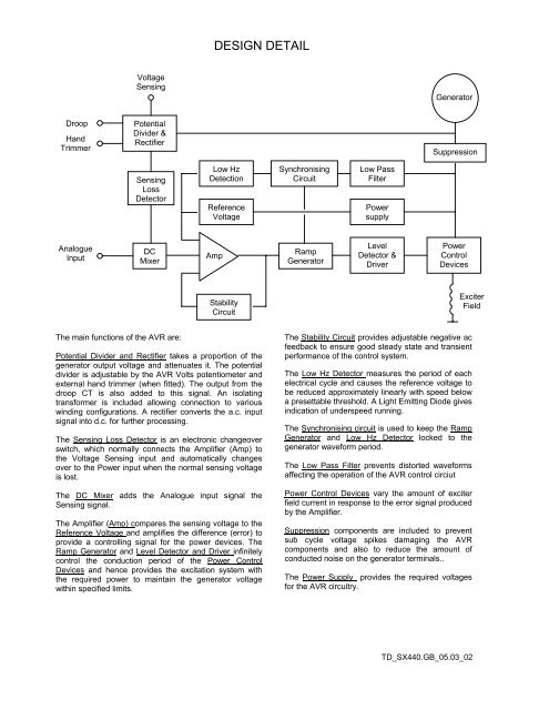
The main functions of the AVR are:<br />
Potential Divider and Rectifier takes a proportion of the<br />
generator output <strong>voltage</strong> and attenuates it. The potential<br />
divider is adjustable by the AVR Volts potentiometer and<br />
external hand trimmer (when fitted). The output from the<br />
droop CT is also added to this signal. An isolating<br />
transformer is included allowing connection to various<br />
winding configurations. A rectifier converts the a.c. input<br />
signal into d.c. for further processing.<br />
The Sensing Loss Detector is an electronic changeover<br />
switch, which normally connects the Amplifier (Amp) to<br />
the Voltage Sensing input and <strong>automatic</strong>ally changes<br />
over to the <strong>Power</strong> input when the normal sensing <strong>voltage</strong><br />
is lost.<br />
The DC Mixer adds the Analogue input signal the<br />
Sensing signal.<br />
The Amplifier (Amp) compares the sensing <strong>voltage</strong> to the<br />
Reference Voltage and amplifies the difference (error) to<br />
provide a controlling signal for the power devices. The<br />
Ramp Generator and Level Detector and Driver infinitely<br />
control the conduction period of the <strong>Power</strong> Control<br />
Devices and hence provides the excitation system with<br />
the required power to maintain the generator <strong>voltage</strong><br />
within specified limits.<br />
The Stability Circuit provides adjustable negative ac<br />
feedback to ensure good steady state and transient<br />
performance of the control system.<br />
The Low Hz Detector measures the period of each<br />
electrical cycle and causes the reference <strong>voltage</strong> to<br />
be reduced approximately linearly with speed below<br />
a presettable threshold. A Light Emitting Diode gives<br />
indication of underspeed running.<br />
The Synchronising circuit is used to keep the Ramp<br />
Generator and Low Hz Detector locked to the<br />
generator waveform period.<br />
The Low Pass Filter prevents distorted waveforms<br />
affecting the operation of the AVR control circiut<br />
<strong>Power</strong> Control Devices vary the amount of exciter<br />
field current in response to the error signal produced<br />
by the Amplifier.<br />
Suppression components are included to prevent<br />
sub cycle <strong>voltage</strong> spikes damaging the AVR<br />
components and also to reduce the amount of<br />
conducted noise on the generator terminals..<br />
The <strong>Power</strong> Supply provides the required <strong>voltage</strong>s<br />
for the AVR circuitry.<br />
TD_SX440.GB_05.03_02